
Hardware Installation Guide
Page 4
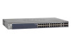
... bottlenecks, boost performance, and increase productivity. 1. Front Panels and LEDs The following : M4100-26G M4100-50G M4100-26-POE M4100-26G-POE M4100-50G-POE+ M4100-50-POE M4100-D10-POE M4100-D12G M4100-12GF M4100-D12G-POE+ M4100-24G-POE+ M4100-12G-POE+ This guide describes hardware installation and basic troubleshooting for each product, visit the NETGEAR website at http://www.netgear.com. The front panel contains LEDs, a Reset button, a USB flash port, RJ45...
... bottlenecks, boost performance, and increase productivity. 1. Front Panels and LEDs The following : M4100-26G M4100-50G M4100-26-POE M4100-26G-POE M4100-50G-POE+ M4100-50-POE M4100-D10-POE M4100-D12G M4100-12GF M4100-D12G-POE+ M4100-24G-POE+ M4100-12G-POE+ This guide describes hardware installation and basic troubleshooting for each product, visit the NETGEAR website at http://www.netgear.com. The front panel contains LEDs, a Reset button, a USB flash port, RJ45...

Hardware Installation Guide
Page 7
...Link at 1G Yellow = Link at 100M Blink = ACT SPD/Link/ACT LEDs USB Port Reset button Figure 12. M4100-12G-POE+ front panel PoE (Max 30W per port): Off = No PD Green = PoE Powered Yellow = PoE Fault PoE SPD/Link/ACT RJ45 SPD/Link/ACT mode: Green = 1G Yellow = 10/100M Blink = ACT SPD/Link/ACT.../ACT mode: Green = 1G Yellow = 10/100M Blink = ACT LEDs USB port Reset button Figure 9. NETGEAR Managed Switch Power Fan PD MaxPoE Reset USB PoE (Max 30W per port): Off = No PD Green = PoE Powered Yellow = PoE Fault PoE-PD (Port 1, 2): Off = No PSE Green = PSE 30w Yellow = PSE 15.4w RJ45 SPD/...
...Link at 1G Yellow = Link at 100M Blink = ACT SPD/Link/ACT LEDs USB Port Reset button Figure 12. M4100-12G-POE+ front panel PoE (Max 30W per port): Off = No PD Green = PoE Powered Yellow = PoE Fault PoE SPD/Link/ACT RJ45 SPD/Link/ACT mode: Green = 1G Yellow = 10/100M Blink = ACT SPD/Link/ACT.../ACT mode: Green = 1G Yellow = 10/100M Blink = ACT LEDs USB port Reset button Figure 9. NETGEAR Managed Switch Power Fan PD MaxPoE Reset USB PoE (Max 30W per port): Off = No PD Green = PoE Powered Yellow = PoE Fault PoE-PD (Port 1, 2): Off = No PSE Green = PSE 30w Yellow = PSE 15.4w RJ45 SPD/...

Hardware Installation Guide
Page 8
...NETGEAR Managed Switch Table 1. Note: If combo port media change to fiber, the Ethernet LED changes to PSE getting 802.3at specified power. Off: No fan is supplying power successfully. Solid green: RPS connected (using internal power supply's power). Off: RPS disconnected. Note: Only for M4100-D12G, -24G-POE, D12G-POE, 12G-POE...proper voltage (44 VDC-57 VDC for af, 50 VDC-57 VDC for at least 7 watts of PoE power available for M4100-26G, 50G, 26-POE, 26G-POE, 50G-POE+, and 50-POE Solid green: PD port 1 is occurring on the port at 10/100 Mbps. Blinking yellow: Packet...
...NETGEAR Managed Switch Table 1. Note: If combo port media change to fiber, the Ethernet LED changes to PSE getting 802.3at specified power. Off: No fan is supplying power successfully. Solid green: RPS connected (using internal power supply's power). Off: RPS disconnected. Note: Only for M4100-D12G, -24G-POE, D12G-POE, 12G-POE...proper voltage (44 VDC-57 VDC for af, 50 VDC-57 VDC for at least 7 watts of PoE power available for M4100-26G, 50G, 26-POE, 26G-POE, 50G-POE+, and 50-POE Solid green: PD port 1 is occurring on the port at 10/100 Mbps. Blinking yellow: Packet...

Hardware Installation Guide
Page 9
Blinking yellow: Packet transmission or reception is established on the port. M4100-26G, 50G, 26-POE, 26G-POE, 50G-POE+, and 50-POE rear panels 9 Note: If a combo port media changes to fiber, the copper port LED changes to off status..., a mini USB port (only for M4100-26G, 50G, 26-POE, 26G-POE, 50G-POE+, 50-POE, D12-PoE, and D12G), a redundant power supply connector (only for M4100-26G, 50G, 26-POE, 26G-POE, 50G-POE+, 50-POE, 12GF, 24G-POE+, and 12G-POE+), and a standard AC power receptacle for the supplied power cord. NETGEAR Managed Switch Table 1. Note: If combo...
Blinking yellow: Packet transmission or reception is established on the port. M4100-26G, 50G, 26-POE, 26G-POE, 50G-POE+, and 50-POE rear panels 9 Note: If a combo port media changes to fiber, the copper port LED changes to off status..., a mini USB port (only for M4100-26G, 50G, 26-POE, 26G-POE, 50G-POE+, 50-POE, D12-PoE, and D12G), a redundant power supply connector (only for M4100-26G, 50G, 26-POE, 26G-POE, 50G-POE+, 50-POE, 12GF, 24G-POE+, and 12G-POE+), and a standard AC power receptacle for the supplied power cord. NETGEAR Managed Switch Table 1. Note: If combo...

Hardware Installation Guide
Page 10
... potential damage. NETGEAR Managed Switch Console switch Console ports Lock Power adapter connector Figure 14. M4100-D10-POE and M4100-D12G rear panels Console port RPS Lock power supply connector Figure 15. M4100-D12G-POE+ rear panel AC power connector Safety Instructions Use the following precautions. • Observe and follow service markings. - M4100-12GF, 24G-POE+, 12G-POE+ rear panel...
... potential damage. NETGEAR Managed Switch Console switch Console ports Lock Power adapter connector Figure 14. M4100-D10-POE and M4100-D12G rear panels Console port RPS Lock power supply connector Figure 15. M4100-D12G-POE+ rear panel AC power connector Safety Instructions Use the following precautions. • Observe and follow service markings. - M4100-12GF, 24G-POE+, 12G-POE+ rear panel...

Hardware Installation Guide
Page 20
... or M4100-D10-PoE) or the AC power cord to the rear of the switch, and the other end to a PSE switch. Select an appropriate outlet. 2. NETGEAR Managed Switch Check the Installation Before you connect the power cord, select an AC outlet that is not controlled by a ...wall switch (which can provide full power to the switch). Note: The M4100-26G, 50G, 26-PoE, 26G-PoE, 50-PoE+, 50G-PoE, 12GF, 24G-POE+, 12G-POE+ can also get power using...
... or M4100-D10-PoE) or the AC power cord to the rear of the switch, and the other end to a PSE switch. Select an appropriate outlet. 2. NETGEAR Managed Switch Check the Installation Before you connect the power cord, select an AC outlet that is not controlled by a ...wall switch (which can provide full power to the switch). Note: The M4100-26G, 50G, 26-PoE, 26G-PoE, 50-PoE+, 50G-PoE, 12GF, 24G-POE+, 12G-POE+ can also get power using...
Hardware Installation Guide
Page 27
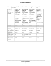
...NETGEAR Managed Switch Table 5. M4100-24G-POE+, D12G-POE+, 12G-POE+, 12GF Gigabit switch physical specification Specification Interface (Auto Uplink on all RJ-45 ports) Bandwidth Weight (Kg) Dimensions (W x D x H) (mm) Mean time between failure (MTBF) Heat dissipation (Btu/hr) Acoustic noise (dB) (ANSI-S10.12) Maximum power consumption (W) (100-240V AC, 50-60 Hz) M4100-24G-POE...-232 console port 1 USB mini B console port 48 Gbps 4.368 440 x 257 x 43.2 M4100-D12G-POE+ M4100-12G-POE+ (GSM5212P) (GSM7212P) M4100-12GF (GSM7212F) 12 RJ-45 ports for 10/100/1000 Mbps 12 RJ-45 ports for 10/100...
...NETGEAR Managed Switch Table 5. M4100-24G-POE+, D12G-POE+, 12G-POE+, 12GF Gigabit switch physical specification Specification Interface (Auto Uplink on all RJ-45 ports) Bandwidth Weight (Kg) Dimensions (W x D x H) (mm) Mean time between failure (MTBF) Heat dissipation (Btu/hr) Acoustic noise (dB) (ANSI-S10.12) Maximum power consumption (W) (100-240V AC, 50-60 Hz) M4100-24G-POE...-232 console port 1 USB mini B console port 48 Gbps 4.368 440 x 257 x 43.2 M4100-D12G-POE+ M4100-12G-POE+ (GSM5212P) (GSM7212P) M4100-12GF (GSM7212F) 12 RJ-45 ports for 10/100/1000 Mbps 12 RJ-45 ports for 10/100...
CLI Manual
Page 1
ProSafe Managed Switch Command Line Interface (CLI) User Manual 350 East Plumeria Drive San Jose, CA 95134 USA February 2013 202-11166-02 1.0 10.0.1 M7100-24X M4100-24G-POE+ M4100-26G M4100-26-POE M4100-26G-POE M4100-50G M4100-50-POE M4100-50G-POE+ M4100-12GF M4100-12G-POE+ M4100-D12G M4100-D10-POE M4100-D12G-POE+
ProSafe Managed Switch Command Line Interface (CLI) User Manual 350 East Plumeria Drive San Jose, CA 95134 USA February 2013 202-11166-02 1.0 10.0.1 M7100-24X M4100-24G-POE+ M4100-26G M4100-26-POE M4100-26G-POE M4100-50G M4100-50-POE M4100-50G-POE+ M4100-12GF M4100-12G-POE+ M4100-D12G M4100-D10-POE M4100-D12G-POE+
CLI Manual
Page 734
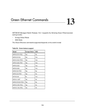
... switch model Table 56. Green feature support Model Energy-Detect EEE M4100-D10-POE Yes No M4100-D12G Yes Yes M4100-50G-POE+ Yes Yes M4100-26G-POE Yes Yes M4100-50G Yes Yes M4100-26G Yes Yes M4100-50-POE Yes No M4100-26-POE Yes No M7100-24x No Yes M4100-12GF Yes No M4100-D12G-POE+ Yes No M4100-24G-POE+ Yes No M4100-12G-POE+ Yes No 734 13.
... switch model Table 56. Green feature support Model Energy-Detect EEE M4100-D10-POE Yes No M4100-D12G Yes Yes M4100-50G-POE+ Yes Yes M4100-26G-POE Yes Yes M4100-50G Yes Yes M4100-26G Yes Yes M4100-50-POE Yes No M4100-26-POE Yes No M7100-24x No Yes M4100-12GF Yes No M4100-D12G-POE+ Yes No M4100-24G-POE+ Yes No M4100-12G-POE+ Yes No 734 13.

