JGSM7224 Hardware Installation Guide
Page 2
ProSafe™ 24-Port Managed Switch JGSM7224 © 2011 NETGEAR, Inc. Technical Support Thank you for more information about the topics covered in any form or by any means without the written permission of their respective holders. © 2011 NETGEAR, Inc. To register your product, get the latest product updates, get support online, or for choosing NETGEAR. NETGEAR does not assume any liability...
ProSafe™ 24-Port Managed Switch JGSM7224 © 2011 NETGEAR, Inc. Technical Support Thank you for more information about the topics covered in any form or by any means without the written permission of their respective holders. © 2011 NETGEAR, Inc. To register your product, get the latest product updates, get support online, or for choosing NETGEAR. NETGEAR does not assume any liability...
JGSM7224 Hardware Installation Guide
Page 3
... 4 JGSM7224 Rear Panel 5 Interpreting the LEDs 5 Safety Instructions 5 Chapter 2 Hardware Installation Package Contents 8 Protecting Against Electrostatic Discharge 8 Unpacking the Hardware 9 Installation 9 Selecting a Location 10 Installing the Switch 10 Checking the Installation 11 Connecting to Power and Check the LEDs 12 SFP Modules 12 Connecting Equipment to the Switch 13 RJ-45 Ports 13 Connecting a Console to the Switch 13 Chapter 3 Troubleshooting Troubleshooting Chart 15 Additional Troubleshooting Suggestions 16 Appendix A Default Settings and Technical Specifications...
... 4 JGSM7224 Rear Panel 5 Interpreting the LEDs 5 Safety Instructions 5 Chapter 2 Hardware Installation Package Contents 8 Protecting Against Electrostatic Discharge 8 Unpacking the Hardware 9 Installation 9 Selecting a Location 10 Installing the Switch 10 Checking the Installation 11 Connecting to Power and Check the LEDs 12 SFP Modules 12 Connecting Equipment to the Switch 13 RJ-45 Ports 13 Connecting a Console to the Switch 13 Chapter 3 Troubleshooting Troubleshooting Chart 15 Additional Troubleshooting Suggestions 16 Appendix A Default Settings and Technical Specifications...

JGSM7224 Hardware Installation Guide
Page 4
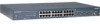
... be free standing, or rack mounted in a wiring closet or an equipment room. For information about features for the ProSafe™ 24-Port Managed Switch JGSM7224. For information about the LEDs on the front panel of the switch, see the NETGEAR website at http://www.netgear.com. 1. The front panel contains LEDs, a RST (reset) button, a USB port, RJ-45 jacks, and copper/fiber combo ports. Port LEDs Console Port Power LED RJ-45 Ports Copper/fiber combo ports Reset button Figure...
... be free standing, or rack mounted in a wiring closet or an equipment room. For information about features for the ProSafe™ 24-Port Managed Switch JGSM7224. For information about the LEDs on the front panel of the switch, see the NETGEAR website at http://www.netgear.com. 1. The front panel contains LEDs, a RST (reset) button, a USB port, RJ-45 jacks, and copper/fiber combo ports. Port LEDs Console Port Power LED RJ-45 Ports Copper/fiber combo ports Reset button Figure...

JGSM7224 Hardware Installation Guide
Page 5
.... Table 1. Current valid link is changed to SFP, the RJ-45 LEDs change to Off status. SFP Ports (1 LED per port) Link/ACT • Off. No SFP module link is established on the port. • Solid green. Introduction 5 A valid link is established on the port. • Blinking green. FDX • Off. Note: If port 23-24 for the supplied power cord. Current valid link is changed to fiber, the copper LEDs change to off status. A valid 1000 Mbps SFP module link is booting up...
.... Table 1. Current valid link is changed to SFP, the RJ-45 LEDs change to Off status. SFP Ports (1 LED per port) Link/ACT • Off. No SFP module link is established on the port. • Solid green. Introduction 5 A valid link is established on the port. • Blinking green. FDX • Off. Note: If port 23-24 for the supplied power cord. Current valid link is changed to fiber, the copper LEDs change to off status. A valid 1000 Mbps SFP module link is booting up...

JGSM7224 Hardware Installation Guide
Page 6
... components. • Use the product only with a power cable for your system or for any objects into the product. - ProSafe™ 24-Port Managed Switch JGSM7224 Safety Instructions Use the following safety guidelines to ensure your own personal safety and to the equipment, observe the following conditions occur, unplug the product from the electrical outlet and replace the part, or contact your...
... components. • Use the product only with a power cable for your system or for any objects into the product. - ProSafe™ 24-Port Managed Switch JGSM7224 Safety Instructions Use the following safety guidelines to ensure your own personal safety and to the equipment, observe the following conditions occur, unplug the product from the electrical outlet and replace the part, or contact your...

JGSM7224 Hardware Installation Guide
Page 7
... or tripped over. ProSafe™ 24-Port Managed Switch JGSM7224 cable that is approved for use in electrical power, use a surge suppressor, line conditioner, or uninterruptible power supply (UPS). • Position system cables and power cables carefully; If you must be stepped on any cables. • Do not modify power cables or plugs. Avoid sudden stops and uneven surfaces. route cables so that they cannot be rated for the product and...
... or tripped over. ProSafe™ 24-Port Managed Switch JGSM7224 cable that is approved for use in electrical power, use a surge suppressor, line conditioner, or uninterruptible power supply (UPS). • Position system cables and power cables carefully; If you must be stepped on any cables. • Do not modify power cables or plugs. Avoid sudden stops and uneven surfaces. route cables so that they cannot be rated for the product and...
JGSM7224 Hardware Installation Guide
Page 8
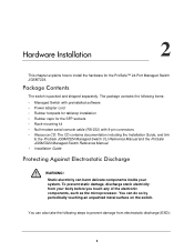
...; Rack-mounting kit • Null-modem serial console cable (RS-232) with preinstalled software • Power adapter cord • Rubber footpads for tabletop installation • Rubber caps for the ProSafe™ 24-Port Managed Switch JGSM7224. Package Contents The switch is packed and shipped separately. Static electricity can do so by periodically touching an unpainted metal surface on the switch. Hardware Installation 2 This chapter explains how to the ProSafe JGSM7224 Managed Switch CLI Reference Manual and...
...; Rack-mounting kit • Null-modem serial console cable (RS-232) with preinstalled software • Power adapter cord • Rubber footpads for tabletop installation • Rubber caps for the ProSafe™ 24-Port Managed Switch JGSM7224. Package Contents The switch is packed and shipped separately. Static electricity can do so by periodically touching an unpainted metal surface on the switch. Hardware Installation 2 This chapter explains how to the ProSafe JGSM7224 Managed Switch CLI Reference Manual and...

JGSM7224 Hardware Installation Guide
Page 9
.... Make sure that all items are present. See Installing the Switch on page 8. Hardware Installation 9 Inspect the products and accessories for replacement. 5. Installation Install the equipment in the following section, Selecting a Location ." 2. When unpacking a static-sensitive component from the boxes. Remove all straps securing the container. 2. Apply power and check the LEDs. ProSafe™ 24-Port Managed Switch JGSM7224 1. Report any item is found missing or damaged...
.... Make sure that all items are present. See Installing the Switch on page 8. Hardware Installation 9 Inspect the products and accessories for replacement. 5. Installation Install the equipment in the following section, Selecting a Location ." 2. When unpacking a static-sensitive component from the boxes. Remove all straps securing the container. 2. Apply power and check the LEDs. ProSafe™ 24-Port Managed Switch JGSM7224 1. Report any item is found missing or damaged...

JGSM7224 Hardware Installation Guide
Page 10
...). ProSafe™ 24-Port Managed Switch JGSM7224 Selecting a Location The switch can be mounted in a standard 19-inch (48.26-centimeter) rack, wall mounted, or left freestanding (placed on all sides for cooling. Table 1. Environment Install the switch in a site free from heat sources such as radio transmitters, broadcast amplifiers, power lines, and fluorescent lighting fixtures. Ventilation Do not restrict airflow by a wall switch, which can install the switch...
...). ProSafe™ 24-Port Managed Switch JGSM7224 Selecting a Location The switch can be mounted in a standard 19-inch (48.26-centimeter) rack, wall mounted, or left freestanding (placed on all sides for cooling. Table 1. Environment Install the switch in a site free from heat sources such as radio transmitters, broadcast amplifiers, power lines, and fluorescent lighting fixtures. Ventilation Do not restrict airflow by a wall switch, which can install the switch...

JGSM7224 Hardware Installation Guide
Page 12
... end to ensure that is not controlled by a wall switch (which can turn off power to Power and Check the LEDs The switch does not have an On/Off switch. ProSafe™ 24-Port Managed Switch JGSM7224 Connecting to the switch). The only way to apply or remove power is good. Check the Power LED on self-test (POST). • If the switch passes the test, the LED turns green. SFP modules are sold separately. Figure 2. Hardware Installation 12
... end to ensure that is not controlled by a wall switch (which can turn off power to Power and Check the LEDs The switch does not have an On/Off switch. ProSafe™ 24-Port Managed Switch JGSM7224 Connecting to the switch). The only way to apply or remove power is good. Check the Power LED on self-test (POST). • If the switch passes the test, the LED turns green. SFP modules are sold separately. Figure 2. Hardware Installation 12
JGSM7224 Hardware Installation Guide
Page 13
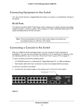
... (shipped with an RJ-45 connector. To use the command line interface (CLI) to 328 feet (100 meters). You can connect devices, a Gigabit Ethernet module, a console, or a combination of the switch. Note: Ethernet specifications limit the cable length between the switch and the attached device to identify the IP address. Hardware Installation 13 ProSafe™ 24-Port Managed Switch JGSM7224 Connecting Equipment to the Switch You can use a console you are stacking switches, see Connecting a Redundant Power Supply (RPS) on page 14.
... (shipped with an RJ-45 connector. To use the command line interface (CLI) to 328 feet (100 meters). You can connect devices, a Gigabit Ethernet module, a console, or a combination of the switch. Note: Ethernet specifications limit the cable length between the switch and the attached device to identify the IP address. Hardware Installation 13 ProSafe™ 24-Port Managed Switch JGSM7224 Connecting Equipment to the Switch You can use a console you are stacking switches, see Connecting a Redundant Power Supply (RPS) on page 14.
JGSM7224 Hardware Installation Guide
Page 14
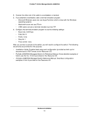
... terminal. 3. The following settings: • Baud rate: 9,600 bps • Data bits: 8 • Parity: none • Stop bit: 1 • Flow control: none After you connect a console to configure the switch. A link is provided on the Resource CD. ProSafe™ 24-Port Managed Switch JGSM7224 2. A link is provided on the Resource CD). • ProSafe JGSM7224 Managed Switch CLI Reference Manual. Describes configuration examples. Gives detailed examples of the cable to use the following documents are provided for this purpose: • Installation Guide. Hardware Installation...
... terminal. 3. The following settings: • Baud rate: 9,600 bps • Data bits: 8 • Parity: none • Stop bit: 1 • Flow control: none After you connect a console to configure the switch. A link is provided on the Resource CD. ProSafe™ 24-Port Managed Switch JGSM7224 2. A link is provided on the Resource CD). • ProSafe JGSM7224 Managed Switch CLI Reference Manual. Describes configuration examples. Gives detailed examples of the cable to use the following documents are provided for this purpose: • Installation Guide. Hardware Installation...
JGSM7224 Hardware Installation Guide
Page 15
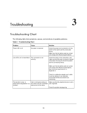
... message log. 15 Check for the switch at both the switch and the connecting device. Cause No power is received Link LED is off or intermittent. See Technical Specifications in an alternate environment where all cables used are correct and comply with Ethernet specifications. Make sure that all products are not the same. Troubleshooting 3 Troubleshooting Chart The following table lists symptoms, causes, and solutions of possible problems. Table 1. Troubleshooting Chart Problem Power LED...
... message log. 15 Check for the switch at both the switch and the connecting device. Cause No power is received Link LED is off or intermittent. See Technical Specifications in an alternate environment where all cables used are correct and comply with Ethernet specifications. Make sure that all products are not the same. Troubleshooting 3 Troubleshooting Chart The following table lists symptoms, causes, and solutions of possible problems. Table 1. Troubleshooting Chart Problem Power LED...
JGSM7224 Hardware Installation Guide
Page 16
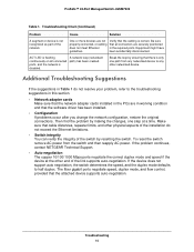
... that there is correct. The fiber gigabit ports negotiate speed, duplex mode, and flow control, provided that the software driver has been installed. • Configuration If problems occur after you change the network configuration, restore the original connections. ProSafe™ 24-Port Managed Switch JGSM7224 Table 1. Troubleshooting Chart (Continued) Problem Cause Solution A segment or device is disabled. A network loop (redundant path) has been created. To reset the switch remove AC power from any networked device to any other networked device. Make sure that...
... that there is correct. The fiber gigabit ports negotiate speed, duplex mode, and flow control, provided that the software driver has been installed. • Configuration If problems occur after you change the network configuration, restore the original connections. ProSafe™ 24-Port Managed Switch JGSM7224 Table 1. Troubleshooting Chart (Continued) Problem Cause Solution A segment or device is disabled. A network loop (redundant path) has been created. To reset the switch remove AC power from any networked device to any other networked device. Make sure that...
JGSM7224 Hardware Installation Guide
Page 17
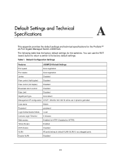
... JGSM7224 Default Settings Port speed Auto negotiation Port duplex Auto negotiation Jumbo Disabled Flow control (half duplex) Disabled Flow control (full duplex) Disabled Broadcast storm control Disabled Rate Limit Disabled Gigabit port type Auto detect Management IP configuration DHCP, 169.254.100.100/16 will be set if dynamic get failed User name Admin Password password Login Authentication Mode Local Console Login TimeOut 5 minutes Web access Enabled for HTTP, Disabled for HTTPS Telnet Access Enabled SSH Access Disabled VLAN All ports belong to its factory...
... JGSM7224 Default Settings Port speed Auto negotiation Port duplex Auto negotiation Jumbo Disabled Flow control (half duplex) Disabled Flow control (full duplex) Disabled Broadcast storm control Disabled Rate Limit Disabled Gigabit port type Auto detect Management IP configuration DHCP, 169.254.100.100/16 will be set if dynamic get failed User name Admin Password password Login Authentication Mode Local Console Login TimeOut 5 minutes Web access Enabled for HTTP, Disabled for HTTPS Telnet Access Enabled SSH Access Disabled VLAN All ports belong to its factory...

JGSM7224 Hardware Installation Guide
Page 18
...; 24-Port Managed Switch JGSM7224 Table 1. Default Configuration Settings (Continued) Features VOICE VLAN Dynamic VLAN (MAC and IP-Subnet based) Spanning Tree Protocol Link aggregation Port mirroring ACL MAC address aging SNMP community RMON VLAN Ingress filtering MAC Filter Port Security Private Group TACACS PLUS SNTP SYSLOG DHCP Server DHCP l2 relay DHCP Client BOOT Client IPv6 Green Ethernet 802.1x Protected ports IGMP SNOOPING Auto Video QoS LLDP and LLDP-MED JGSM7224 Default Settings Disabled Disabled Enabled (IEEE 802.1s) Disabled Disabled Disabled 300 seconds Public (read-only access...
...; 24-Port Managed Switch JGSM7224 Table 1. Default Configuration Settings (Continued) Features VOICE VLAN Dynamic VLAN (MAC and IP-Subnet based) Spanning Tree Protocol Link aggregation Port mirroring ACL MAC address aging SNMP community RMON VLAN Ingress filtering MAC Filter Port Security Private Group TACACS PLUS SNTP SYSLOG DHCP Server DHCP l2 relay DHCP Client BOOT Client IPv6 Green Ethernet 802.1x Protected ports IGMP SNOOPING Auto Video QoS LLDP and LLDP-MED JGSM7224 Default Settings Disabled Disabled Enabled (IEEE 802.1s) Disabled Disabled Disabled 300 seconds Public (read-only access...
JGSM7224 Hardware Installation Guide
Page 19
...; Broadcast/Multicast/DFL storm control • Ingress/Egress rate limit • Telnet sessions for management CPU (5) • Ping support • Traceroute support • Private enterprise MIB • Configuration file upload, download (TFTP and HTTP) • Runtime image download (TFTP and HTTP) • Command line interface • Web-based graphic user interface • Simple Network Time Protocol (SNTP) • Syslog • SSLv3/TLSv1.0 Web security • Secured Shell (SSHv1, v2) • 802.1Q Static VLAN (Up...
...; Broadcast/Multicast/DFL storm control • Ingress/Egress rate limit • Telnet sessions for management CPU (5) • Ping support • Traceroute support • Private enterprise MIB • Configuration file upload, download (TFTP and HTTP) • Runtime image download (TFTP and HTTP) • Command line interface • Web-based graphic user interface • Simple Network Time Protocol (SNTP) • Syslog • SSLv3/TLSv1.0 Web security • Secured Shell (SSHv1, v2) • 802.1Q Static VLAN (Up...
JGSM7224 Hardware Installation Guide
Page 20
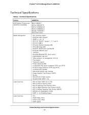
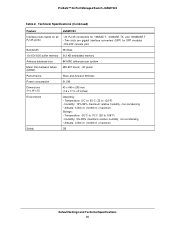
...Address database size Mean time between failure (MTBF) Performance Power consumption Dimensions (H x W x D) Environment Safety JGSM7224 • 24 RJ-45 connectors for 10BASE-T, 100BASE-TX, and 1000BASE-T • Two slots are gigabit interface converters (SFP) for SFP modules • RS-232 console port 48 Gbps 512 KB embedded memory 8K MAC addresses per system 280,607 hours( ~32 years) Store-and-forward... humidity, non-condensing • Altitude: 3,000 m (10,000 ft.) maximum CB Default Settings and Technical Specifications 20 ProSafe™ 24-Port Managed Switch JGSM7224 Table 2.
...Address database size Mean time between failure (MTBF) Performance Power consumption Dimensions (H x W x D) Environment Safety JGSM7224 • 24 RJ-45 connectors for 10BASE-T, 100BASE-TX, and 1000BASE-T • Two slots are gigabit interface converters (SFP) for SFP modules • RS-232 console port 48 Gbps 512 KB embedded memory 8K MAC addresses per system 280,607 hours( ~32 years) Store-and-forward... humidity, non-condensing • Altitude: 3,000 m (10,000 ft.) maximum CB Default Settings and Technical Specifications 20 ProSafe™ 24-Port Managed Switch JGSM7224 Table 2.
JGSM7224 Install Guide
Page 1
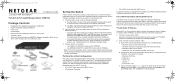
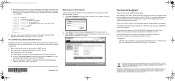
...-modem cable supplied with the switch, connect a VT100/ANSI terminal or a workstation to the switch using the Command Line Interface (CLI) through its Web interface, or by a PC NIC port when in DHCP-client mode without DHCP Server If no DHCP server is set up. • PC in DHCP client mode without DHCP server • PC with static IP address • PC in DHCP client mode with the kit,. 2. Start a terminal emulation program (TEP). At the command prompt User:, login to the switch port labeled Console...
...-modem cable supplied with the switch, connect a VT100/ANSI terminal or a workstation to the switch using the Command Line Interface (CLI) through its Web interface, or by a PC NIC port when in DHCP-client mode without DHCP Server If no DHCP server is set up. • PC in DHCP client mode without DHCP server • PC with static IP address • PC in DHCP client mode with the kit,. 2. Start a terminal emulation program (TEP). At the command prompt User:, login to the switch port labeled Console...
JGSM7224 Install Guide
Page 2
... the serial console port. 1. Refer to http://support.netgear.com for the password field. 3. After installing your switch. c. End each command line with Static IP Address. JGSM7224 IG 31Aug11.fm Page 2 Wednesday, August 31, 2011 9:39 AM d. Use this IP address to login to configure your device, locate the serial number on the Waste Electrical and Electronic Equipment (the WEEE Directive). You can use the switch menu to the switch through its Web Management interface (see the User Manual...
... the serial console port. 1. Refer to http://support.netgear.com for the password field. 3. After installing your switch. c. End each command line with Static IP Address. JGSM7224 IG 31Aug11.fm Page 2 Wednesday, August 31, 2011 9:39 AM d. Use this IP address to login to configure your device, locate the serial number on the Waste Electrical and Electronic Equipment (the WEEE Directive). You can use the switch menu to the switch through its Web Management interface (see the User Manual...


