
GS7xxTPS Hardware manual
Page 2
...üllung der Vorschriften hin zu überprüfen. E-mail: support@netgear.com North American NETGEAR web site: http://www.netgear.com Trademarks NETGEAR, the NETGEAR logo, and Auto Uplink are registered trademarks or trademarks of NETGEAR, Inc. Microsoft, Windows, and Windows NT are copyright Intoto, Inc. Please...the standards set out in such residential areas. The Federal Office for Interference by NETGEAR, Inc. Bestätigung des Herstellers/Importeurs Es wird hiermit bestätigt, daß das Switch gemäß der im BMPT-AmtsblVfg 243/1991 und Vfg 46/1992 ...
...üllung der Vorschriften hin zu überprüfen. E-mail: support@netgear.com North American NETGEAR web site: http://www.netgear.com Trademarks NETGEAR, the NETGEAR logo, and Auto Uplink are registered trademarks or trademarks of NETGEAR, Inc. Microsoft, Windows, and Windows NT are copyright Intoto, Inc. Please...the standards set out in such residential areas. The Federal Office for Interference by NETGEAR, Inc. Bestätigung des Herstellers/Importeurs Es wird hiermit bestätigt, daß das Switch gemäß der im BMPT-AmtsblVfg 243/1991 und Vfg 46/1992 ...
GS7xxTPS Hardware manual
Page 3
...in the United States FCC Information to User This product does not contain any other antenna or transmitter. FCC Declaration Of Conformity We NETGEAR, Inc., 4500 Great America Parkway, Santa Clara, CA 95054, declare under our sole responsibility that may cause undesired operation. This ...subject to comply with approved antennas only. This transmitter must accept any interference received, including interference that the model GS700TPS Gigabit Stackable Smart Switch with PoE complies with minimum distance of 20 cm between the radiator and your version of the end-user to the following...
...in the United States FCC Information to User This product does not contain any other antenna or transmitter. FCC Declaration Of Conformity We NETGEAR, Inc., 4500 Great America Parkway, Santa Clara, CA 95054, declare under our sole responsibility that may cause undesired operation. This ...subject to comply with approved antennas only. This transmitter must accept any interference received, including interference that the model GS700TPS Gigabit Stackable Smart Switch with PoE complies with minimum distance of 20 cm between the radiator and your version of the end-user to the following...

GS7xxTPS Hardware manual
Page 4
...operate the equipment. Canadian Department of Communications Radio Interference Regulations This digital apparatus (GS700TPS Gigabit Stackable Smart Switch with FCC Standards FOR HOME OR OFFICE USE Modifications made to the product, unless expressly approved by NETGEAR, Inc., could void the user's right to Comply with PoE) does not exceed the...Publication Date: Product Family: Product Name: Home or Business Product: Language: Publication Part Number: Publication Version Number: GS700TPS April 2009 Smart Switch GS700TPS Smart Switch Business English 202-10488-01 1.0 iv v1.0, April 2009
...operate the equipment. Canadian Department of Communications Radio Interference Regulations This digital apparatus (GS700TPS Gigabit Stackable Smart Switch with FCC Standards FOR HOME OR OFFICE USE Modifications made to the product, unless expressly approved by NETGEAR, Inc., could void the user's right to Comply with PoE) does not exceed the...Publication Date: Product Family: Product Name: Home or Business Product: Language: Publication Part Number: Publication Version Number: GS700TPS April 2009 Smart Switch GS700TPS Smart Switch Business English 202-10488-01 1.0 iv v1.0, April 2009

GS7xxTPS Hardware manual
Page 5
... 5: Installing an SFP GBIC Module 2-5 Step 6 Installing Device as Stand-alone or Stack Master 2-5 Step 7: Applying AC Power 2-7 Step 8: Managing the Switch via a Web Browser/PC Utility for Initial Configuration ......2-7 Chapter 3 Physical Description Front and Back Panel Configuration 3-1 LED Designations ...3-3 Device Hardware Interfaces 3-5 Appendix A Troubleshooting ...
... 5: Installing an SFP GBIC Module 2-5 Step 6 Installing Device as Stand-alone or Stack Master 2-5 Step 7: Applying AC Power 2-7 Step 8: Managing the Switch via a Web Browser/PC Utility for Initial Configuration ......2-7 Chapter 3 Physical Description Front and Back Panel Configuration 3-1 LED Designations ...3-3 Device Hardware Interfaces 3-5 Appendix A Troubleshooting ...

GS7xxTPS Hardware manual
Page 7
The NETGEAR® Installation Manual describes how to the equipment. Conventions, Formats and Scope The conventions, formats, ...a procedure that will save time or resources. The information in a malfunction or damage to install, configure and troubleshoot the smart switch. Danger: This is intended for readers with intermediate computer and Internet skills. About This Guide Congratulations on the purchase of note ...text, file and server names, extensions, commands, IP addresses • Formats. Warning: Ignoring this type of the NETGEAR Smart Switch. vii v1.0, April 2009
The NETGEAR® Installation Manual describes how to the equipment. Conventions, Formats and Scope The conventions, formats, ...a procedure that will save time or resources. The information in a malfunction or damage to install, configure and troubleshoot the smart switch. Danger: This is intended for readers with intermediate computer and Internet skills. About This Guide Congratulations on the purchase of note ...text, file and server names, extensions, commands, IP addresses • Formats. Warning: Ignoring this type of the NETGEAR Smart Switch. vii v1.0, April 2009

GS7xxTPS Hardware manual
Page 8
...top left of any page in the HTML version of the manual is described in the table of contents and the button. GS700TPS Smart Switch • Scope. web site at http://www.adobe.com. The Acrobat reader is written for a particular product model. ...• Links to these specifications: Product Version Manual Publication Date GS700TPS Smart Switch April 2009 Note: Product updates are available on a link in the manual. • The button accesses the full NETGEAR, Inc. How to your requirements. • Printing a Page in a browser window. ...
...top left of any page in the HTML version of the manual is described in the table of contents and the button. GS700TPS Smart Switch • Scope. web site at http://www.adobe.com. The Acrobat reader is written for a particular product model. ...• Links to these specifications: Product Version Manual Publication Date GS700TPS Smart Switch April 2009 Note: Product updates are available on a link in the manual. • The button accesses the full NETGEAR, Inc. How to your requirements. • Printing a Page in a browser window. ...

GS7xxTPS Hardware manual
Page 9
..., you can save paper and printer ink by selecting this feature. • Printing the Full Manual - Click the print icon in a browser window. - GS700TPS Smart Switch -
..., you can save paper and printer ink by selecting this feature. • Printing the Full Manual - Click the print icon in a browser window. - GS700TPS Smart Switch -
GS7xxTPS Hardware manual
Page 11
... the added feature of Power over Ethernet (PoE). • GS748TPS - You can view the switch's many features and use out of the box. With a Web-based Graphical User Interface (GUI), you can make high-speed connections using the Gigabit ports. Chapter 1 Introduction The NETGEAR Smart Switch is a state-of-the-art, high-performance, IEEE...
... the added feature of Power over Ethernet (PoE). • GS748TPS - You can view the switch's many features and use out of the box. With a Web-based Graphical User Interface (GUI), you can make high-speed connections using the Gigabit ports. Chapter 1 Introduction The NETGEAR Smart Switch is a state-of-the-art, high-performance, IEEE...
GS7xxTPS Hardware manual
Page 12
... of Service (CoS) for fiber connections using SFP GBIC modules. 1-2 Introduction v1.0, April 2009 or full-duplex mode. The GS700TPS Smart Switch can automatically negotiate to the highest speed. The maximum segment length is IEEE-compliant and offers low latency for environments that runs on a ...PC. All ports can be free-standing, or rack mounted in half- This capability makes the switch ideal for high-speed networking. In addition, all RJ-45 ports operate in a wiring closet or equipment room. These features provide better...
... of Service (CoS) for fiber connections using SFP GBIC modules. 1-2 Introduction v1.0, April 2009 or full-duplex mode. The GS700TPS Smart Switch can automatically negotiate to the highest speed. The maximum segment length is IEEE-compliant and offers low latency for environments that runs on a ...PC. All ports can be free-standing, or rack mounted in half- This capability makes the switch ideal for high-speed networking. In addition, all RJ-45 ports operate in a wiring closet or equipment room. These features provide better...

GS7xxTPS Hardware manual
Page 13
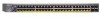
GS700TPS Smart Switch The NETGEAR Smart Switch can be used as a desktop to build a small network that enables 1000 Mbps access to the server or PC can provide 2000 Mbps throughput. With full-duplex enabled, the switch port connected to a file server. Introduction 1-3 v1.0, April 2009 Figure 1-1 Switch Features The following list identifies the key features of the NETGEAR Smart Switch. • On the GS700TPS Smart Switch device there are 48 RJ-45 ports 10/100/1000M auto sensing Gigabit Ethernet switching ports, four of which are Combo ports.
GS700TPS Smart Switch The NETGEAR Smart Switch can be used as a desktop to build a small network that enables 1000 Mbps access to the server or PC can provide 2000 Mbps throughput. With full-duplex enabled, the switch port connected to a file server. Introduction 1-3 v1.0, April 2009 Figure 1-1 Switch Features The following list identifies the key features of the NETGEAR Smart Switch. • On the GS700TPS Smart Switch device there are 48 RJ-45 ports 10/100/1000M auto sensing Gigabit Ethernet switching ports, four of which are Combo ports.

GS7xxTPS Hardware manual
Page 14
...duplex back-pressure control. • Per port LEDs, System LEDs. • Internal power supply. 1-4 Introduction v1.0, April 2009 GS700TPS Smart Switch • Four Small Form-factor Pluggable (SFP) GBIC slots, which function as combo ports. and half-duplex functions for all ports. •...RJ-45 copper. Combo ports are supported: • 1000Base-SX • 1000Base-LX • 100Base-FX • The device supports full Netgear Smart Switch functionality. • The device provides full compatibility with IEEE standards: • IEEE 802.3i, (10Base-T) • IEEE 802.3u (100Base...
...duplex back-pressure control. • Per port LEDs, System LEDs. • Internal power supply. 1-4 Introduction v1.0, April 2009 GS700TPS Smart Switch • Four Small Form-factor Pluggable (SFP) GBIC slots, which function as combo ports. and half-duplex functions for all ports. •...RJ-45 copper. Combo ports are supported: • 1000Base-SX • 1000Base-LX • 100Base-FX • The device supports full Netgear Smart Switch functionality. • The device provides full compatibility with IEEE standards: • IEEE 802.3i, (10Base-T) • IEEE 802.3u (100Base...

GS7xxTPS Hardware manual
Page 15
..., and assigned a unique Unit ID. The GS724TPS, using data pairs (RJ-45 1, 2, 3 and 6 pin), provides power to the PD. GS748TPS supports the following PoE functions: • Smart Power Managed function handles the power of each port in the event of limited available power. • ...the slave units is named stack slave. The backup master acts as the Stacking Master. A unit serving as the backup master. GS700TPS Smart Switch • Standard 1U high, rack mountable 19"chassis. • Fan speed control supported The GS724TPS supports the following PoE functions: • ...
..., and assigned a unique Unit ID. The GS724TPS, using data pairs (RJ-45 1, 2, 3 and 6 pin), provides power to the PD. GS748TPS supports the following PoE functions: • Smart Power Managed function handles the power of each port in the event of limited available power. • ...the slave units is named stack slave. The backup master acts as the Stacking Master. A unit serving as the backup master. GS700TPS Smart Switch • Standard 1U high, rack mountable 19"chassis. • Fan speed control supported The GS724TPS supports the following PoE functions: • ...

GS7xxTPS Hardware manual
Page 16
... A stack unit can operate in the event of failure of stack master. GS700TPS Smart Switch stack master in one of the following Modes: • Standalone unit runs as a general switch. Switch software is responsible for each stack members. The master and backup master are assigned unit ..., the masterbackup unit will assume the stack-master role. ("Switchover"). • A slave unit only runs a slave version of the Distributed Switching Algorithm, which to a stack. • The Master unit manages the entire stack, and is downloaded separately for the entire stack configuration. The...
... A stack unit can operate in the event of failure of stack master. GS700TPS Smart Switch stack master in one of the following Modes: • Standalone unit runs as a general switch. Switch software is responsible for each stack members. The master and backup master are assigned unit ..., the masterbackup unit will assume the stack-master role. ("Switchover"). • A slave unit only runs a slave version of the Distributed Switching Algorithm, which to a stack. • The Master unit manages the entire stack, and is downloaded separately for the entire stack configuration. The...

GS7xxTPS Hardware manual
Page 17
Figure 1-2 Verify that the package contains the following: • NETGEAR Smart Switch • Stacking Cable • Rubber footpads for tabletop installation • Power cord • Rack-mount Kit for installing the switch in a 19-inch rack • Installation Guide • Smart Switch Resource CD with Smart Wizard Discovery and User's manual • Warranty/Support Information...
Figure 1-2 Verify that the package contains the following: • NETGEAR Smart Switch • Stacking Cable • Rubber footpads for tabletop installation • Power cord • Rack-mount Kit for installing the switch in a 19-inch rack • Installation Guide • Smart Switch Resource CD with Smart Wizard Discovery and User's manual • Warranty/Support Information...

GS7xxTPS Hardware manual
Page 18
GS700TPS Smart Switch 1-8 Introduction v1.0, April 2009
GS700TPS Smart Switch 1-8 Introduction v1.0, April 2009

GS7xxTPS Hardware manual
Page 19
...the switch in the following table. The rack-mount kit supplied with the switch is grounded and physically secure. Switch installation involves the following steps: "Step 1: Preparing the Site" "Step 2: Installing the Switch" ...describes the installation procedures for Initial Configuration" Step 1: Preparing the Site Before installing the switch, ensure the operating environment meets the requirements in a position that is also required. Use...to view the front panel LEDs, and easy safe access to the Switch" "Step 5: Installing an SFP GBIC Module" "Step 6 Installing Device as Stand-alone...
...the switch in the following table. The rack-mount kit supplied with the switch is grounded and physically secure. Switch installation involves the following steps: "Step 1: Preparing the Site" "Step 2: Installing the Switch" ...describes the installation procedures for Initial Configuration" Step 1: Preparing the Site Before installing the switch, ensure the operating environment meets the requirements in a position that is also required. Use...to view the front panel LEDs, and easy safe access to the Switch" "Step 5: Installing an SFP GBIC Module" "Step 6 Installing Device as Stand-alone...

GS7xxTPS Hardware manual
Page 20
... at least 6 ft. (1.83 m) away from heat sources such as a photocopy machine. Step 2: Installing the Switch The NETGEAR Smart Switch can accidentally turn off power to the side of the switch. Insert the screws provided in the rack-mount kit through each bracket. 4. Tighten the screws with four self-adhesive rubber footpads. Power specifications...
... at least 6 ft. (1.83 m) away from heat sources such as a photocopy machine. Step 2: Installing the Switch The NETGEAR Smart Switch can accidentally turn off power to the side of the switch. Insert the screws provided in the rack-mount kit through each bracket. 4. Tighten the screws with four self-adhesive rubber footpads. Power specifications...

GS7xxTPS Hardware manual
Page 21
Figure 2-1 Note: Always install devices from over balancing and toppling over. This will prevent the rack from the bottom of the to the top. Installation 2-3 v1.0, April 2009 Tighten the screws with a #2 Phillips screwdriver to make sure cables are not damaged or creating a safety hazard. Step 3: Checking the Installation Before applying power perform the following: • Inspect the equipment thoroughly. • Verify that all cables are installed correctly. • Check cable routing to secure the switch in the rack. GS700TPS Smart Switch 5.
Figure 2-1 Note: Always install devices from over balancing and toppling over. This will prevent the rack from the bottom of the to the top. Installation 2-3 v1.0, April 2009 Tighten the screws with a #2 Phillips screwdriver to make sure cables are not damaged or creating a safety hazard. Step 3: Checking the Installation Before applying power perform the following: • Inspect the equipment thoroughly. • Verify that all cables are installed correctly. • Check cable routing to secure the switch in the rack. GS700TPS Smart Switch 5.

GS7xxTPS Hardware manual
Page 22
.... Note: Ethernet specifications limit the cable length between the switch and the attached device to an RJ-45 network port on the Switch front panel (Figure 2-2). The NETGEAR Smart Switch contains Auto Uplink™ technology, which allows you to the switch's RJ-45 ports. GS700TPS Smart Switch • Ensure all equipment is mounted properly and securely...
.... Note: Ethernet specifications limit the cable length between the switch and the attached device to an RJ-45 network port on the Switch front panel (Figure 2-2). The NETGEAR Smart Switch contains Auto Uplink™ technology, which allows you to the switch's RJ-45 ports. GS700TPS Smart Switch • Ensure all equipment is mounted properly and securely...

GS7xxTPS Hardware manual
Page 23
... unit runs as a slave unit as described above, and in a chain topology, slave units could be disjointed from the Smart Switch. GS700TPS Smart Switch Step 5: Installing an SFP GBIC Module The following procedure describes how to down state. Standard SFP GBIC modules are sold separately from... the stack (which puts them in the switch's Gigabit module bay. If stacking cable failed or a stack unit extracted in addition, it continuously monitors the existence and operation of...
... unit runs as a slave unit as described above, and in a chain topology, slave units could be disjointed from the Smart Switch. GS700TPS Smart Switch Step 5: Installing an SFP GBIC Module The following procedure describes how to down state. Standard SFP GBIC modules are sold separately from... the stack (which puts them in the switch's Gigabit module bay. If stacking cable failed or a stack unit extracted in addition, it continuously monitors the existence and operation of...

