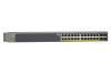
GS728TP/GS728TPP/GS752TP Hardware Installation Guide
Page 1
ProSafe® GS752TP, GS728TP, and GS728TPP Gigabit Smart Switches Hardware Installation Guide 350 East Plumeria Drive San Jose, CA 95134 USA December 2012 202-11136-01 v1.0
GS728TP/GS728TPP/GS752TP Hardware Installation Guide
Page 2
...-11136-01 Version v1.0 Publish Date December 2012 Comments First publication 2 GS752TP, GS728TP, and GS728TPP Gigabit Smart Switches No part of this manual, visit the support website at http://support.netgear.com/app/answers/detail/a_id/984. NETGEAR, the NETGEAR logo, and Connect with Innovation are registered trademarks or trademarks of phone numbers at http...
GS728TP/GS728TPP/GS752TP Hardware Installation Guide
Page 3
...Contents 8 Chapter 2 Physical Description GS752TP Front Panel and Back Panel Configuration 10 GS728TP Front Panel and Back Panel Configuration 11 GS728TPP Front Panel and Back Panel Configuration 12 LED Designations 14 Port LEDs 14 System LEDs 15 Device Hardware Interfaces 16 RJ-45 Ports...Factory Defaults Button 17 Select Button 17 Chapter 3 Applications Desktop Switching 19 Backbone Switching 20 Chapter 4 Installation Step 1: Prepare the Site 22 Step 2: Install the Switch 22 Install the Switch on a Flat Surface 22 Install the Switch in a Rack 22 Step 3: Check the Installation 23 ...
GS728TP/GS728TPP/GS752TP Hardware Installation Guide
Page 4
GS752TP, GS728TP, and GS728TPP Gigabit Smart Switch Appendix A Troubleshooting Troubleshooting Chart 28 Additional Troubleshooting Suggestions 28 Network Adapter Cards 28 Configuration 28 Switch Integrity 29 Autonegotiation 29 Appendix B Technical Specifications Network Protocol and Standards Compatibility 31 Management 31 Interface 32 LEDs 32 Performance Specifications 32 Power Supply 33 Physical Specifications 33 Environmental Specifications 34 Electromagnetic Emissions 34 Safety 34 Appendix C Notification of Compliance Index 4
GS728TP/GS728TPP/GS752TP Hardware Installation Guide
Page 5
... many ports and want the power of the box. The GS752TP, GS728TP, and GS728TPP Gigabit Smart Switches Hardware Installation Guide describes how to the GS752TP, GS728TP, and GS728TPP Gigabit Smart Switch and provides the following information: • Overview • Features • Package... computer and Internet skills. Introduction 1 Congratulations on the GS752TP, GS728TP, and GS728TPP Gigabit Smart Switch. 1. The front panel of your NETGEAR® ProSafeTM GS752TP, GS728TP, and GS728TPP Gigabit Smart Switch. The front panel also has 4 SFP ports that support nonstop 10/100/...
GS728TP/GS728TPP/GS752TP Hardware Installation Guide
Page 6
GS752TP, GS728TP, and GS728TPP Gigabit Smart Switch Overview The NETGEAR GS752TP, GS728TP, and GS728TPP Gigabit Smart Switch provides 48 or 24 twisted-pair ports that runs on a computer. With a web-based graphical user interface (GUI), the switch's many capabilities can be freestanding, or rack ...you can automatically negotiate to support the increased power requirements. • Four dedicated 100M/1000M SFP fiber ports. • Full NETGEAR Smart Switch functionality. • Full compatibility with a complete package of features for increased bandwidth, and Class of the network. It is...
GS728TP/GS728TPP/GS752TP Hardware Installation Guide
Page 7
... address learning function to minimize packet loss and frame drops. • Half-duplex backpressure control. • LEDs. GS752TP, GS728TP, and GS728TPP Gigabit Smart Switch • IEEE 802.3z (1000BASE-x) • IEEE802.3af (DTE Power via MDI) • IEEE802.3at (DTE Power via MDI ... • AutoSensing and auto-negotiating capabilities for each port. • Internal open frame power supply. • Standard NETGEAR 7xx series chassis. • NETGEAR Green product series power-saving features: • Automatic power consumption adjustment based on all ports. • Auto Uplink...
GS728TP/GS728TPP/GS752TP Hardware Installation Guide
Page 8
... 1. Package contents Verify that the package contains the following: • GS752TP, GS728TP, or GS728TPP Gigabit Smart Switch • Rubber footpads for tabletop installation • Rack-mounting kit • Power cord • Installation guide • Smart Switch resource CD with NETGEAR Smart Control Center and user's manual If any item is missing or damaged, contact...
GS728TP/GS728TPP/GS752TP Hardware Installation Guide
Page 9
Physical Description 2 This chapter describes the GS752TP, GS728TP, and GS728TPP Gigabit Smart Switch hardware features. Topics include: • GS752TP Front Panel and Back Panel Configuration • GS728TP Front Panel and Back Panel Configuration • GS728TPP Front Panel and Back Panel Configuration • LED Designations • Device Hardware Interfaces 9 2.
GS728TP/GS728TPP/GS752TP Hardware Installation Guide
Page 10
...following: • 48 RJ-45 connectors for 10/100/1000 Mbps AutoSensing Gigabit Ethernet switching ports. • Ports 1-8 are PoE (15.4W) capable. • Four dedicated 100M/1000 Mbps SFP Gigabit Ethernet switching ports. • Reset button to restart the device. • Recessed Factory Defaults ... the working mode of the port LEDs with the link partner automatically. GS752TP, GS728TP, and GS728TPP Gigabit Smart Switch GS752TP Front Panel and Back Panel Configuration The GS752TP Gigabit Smart Switch has 48 10/100/1000 Mbps copper ports and four dedicated 100/1000 Mbps SFP fiber ports...
GS728TP/GS728TPP/GS752TP Hardware Installation Guide
Page 11
...: • 24 RJ-45 connectors for 10/100/1000 Mbps AutoSensing Gigabit Ethernet switching ports. • Ports 1-8 are PoE (15.4W) capable. • Four dedicated 100M/1000 Mbps SFP Gigabit Ethernet switching ports. • Reset button to restart the device. 11 Figure 4 illustrates the... the duplex mode with the link partner automatically. GS752TP, GS728TP, and GS728TPP Gigabit Smart Switch Figure 3 illustrates the NETGEAR GS752TP Gigabit Smart Switch back panel. Figure 3. Each port is capable of the GS728TP Gigabit Smart Switch. Power, Fan, PoE Max, and LED Mode LEDs Link/ACT LEDs...
GS728TP/GS728TPP/GS752TP Hardware Installation Guide
Page 12
...The back panel contains a power connector. Front panel 12 Figure 5 illustrates the NETGEAR GS728TPP Gigabit Smart Switch back panel. Power connector GS728TPP Front Panel and Back Panel Configuration The GS728TPP Gigabit Smart Switch has 24 10/100/1000 Mbps copper ports and four dedicated 100/1000 Mbps ...and LED Mode LEDs Link/ACT LEDs SFP ports Factory Defaults button Reset button Figure 6. Figure 5. GS752TP, GS728TP, and GS728TPP Gigabit Smart Switch • Recessed Factory Defaults button to restore the device back to the factory defaults. • Select button to change the...
GS728TP/GS728TPP/GS752TP Hardware Installation Guide
Page 13
...; An RPS connector (redundant power supply) Power connector 13 RPS connector Figure 7. GS752TP, GS728TP, and GS728TPP Gigabit Smart Switch The front panel contains the following: • 24 RJ-45 connectors for 10/100/1000 Mbps AutoSensing Gigabit Ethernet switching ports. • Ports 1-24 are PoE+ (30W) capable. • Four dedicated 100M/1000 Mbps... PoE mode or Ethernet mode. • Port Status and Port Speed LEDs. • Power, Fan Status, Max PoE, and LED Mode LEDs. Figure 7 illustrates the NETGEAR GS728TPP Gigabit Smart Switch back panel.
GS728TP/GS728TPP/GS752TP Hardware Installation Guide
Page 14
... copper ports 1-48 or 1-24 Link/ACT Mode LED: • Off. A valid 100 Mbps link is established on PoE power circuit. - GS752TP, GS728TP, and GS728TPP Gigabit Smart Switch LED Designations Port LEDs The following failures resulted in stopping power to that port: - The PoE powered device (PD) is connected and the port...
GS728TP/GS728TPP/GS752TP Hardware Installation Guide
Page 15
... the system is operating normally. • Solid yellow. The fan is drawing power from a remote power supply or PoE power from an external power supply. GS728TPP only. • Solid yellow. GS752TP, GS728TP, and GS728TPP Gigabit Smart Switch System LEDs The following table describes the system LED designations.
GS728TP/GS728TPP/GS752TP Hardware Installation Guide
Page 16
...connections on your network, there are four SFP ports (49 through 52 or 25 through cables when you insert a cable into the switch's RJ-45 port, the switch automatically does the following: • Senses whether the cable is a straight-through or crossover cable. • Determines whether the link... ports support only an unshielded twisted-pair (UTP) cable terminated with the attached device, without requiring user intervention. GS752TP, GS728TP, and GS728TPP Gigabit Smart Switch Device Hardware Interfaces RJ-45 Ports RJ-45 ports are attaching devices. When you are AutoSensing ports.
GS728TP/GS728TPP/GS752TP Hardware Installation Guide
Page 17
...front-panel LEDs turn off and back on. To operate the Factory Defaults button, insert a device such as a paper clip into the switch as the switch performs its factory settings. You need to change the LED mode. 17 When you press the Factory Defaults button, all settings including the password...last saved configuration is equivalent to change the LED mode of the ports between Ethernet and PoE status. Factory Defaults Button The Smart Switch has a Factory Defaults button on the front panel so that you can remove the current configuration and return the device to manually reboot ...
GS728TP/GS728TPP/GS752TP Hardware Installation Guide
Page 18
... GS752TP, GS728TP, and GS728TPP Gigabit Smart Switch can be used as your network connections. With full-duplex mode enabled, the switch port connected to the server or computer can be used as a desktop switch to build a small network that enables users to have 1000 Mbps access to...in configuring your only network traffic-distribution device or with 10 Mbps, 100 Mbps, and 1000 Mbps hubs and switches. Figure 8. 3. It can provide 2000 Mbps throughput. Desktop switching 19 Applications 3 Your GS752TP, GS728TP, and GS728TPP Gigabit Smart Switch is designed to a file server.
GS728TP/GS728TPP/GS752TP Hardware Installation Guide
Page 19
Backbone switching 20 Figure 9. GS752TP, GS728TP, and GS728TPP Gigabit Smart Switch Backbone Switching You can use the GS752TP, GS728TP, and GS728TPP Gigabit Smart Switch as a backbone switch in a small network that gives users high-speed access to servers and other network devices.
GS728TP/GS728TPP/GS752TP Hardware Installation Guide
Page 20
Installation 4 This chapter describes the installation procedures for your GS752TP, GS728TP, and GS728TPP Gigabit Smart Switch. 4. Switch installation involves the following steps: Step 1: Prepare the Site Step 2: Install the Switch Step 3: Check the Installation Step 4: Connect Devices to the Switch Step 5: Install an SFP Transceiver Module Step 6: Apply AC Power Step 7: Apply RPS DC Power Step 8: Manage the Switch Using a Web Browser or the Computer Utility 21