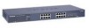

FS726T User Manual
Page 4
....1Q Tag VLAN 3-7 Switch> Trunking Page 3-9 Switch> Monitor Page 3-10 Switch> Advanced> Jumbo Frame 3-10 Switch> Advanced> Spanning Tree Page 3-11 Switch> Advanced> SNMP 3-11 Firmware Menu ...3-12 Firmware> Configuration Backup Page 3-12 Firmware...Based VLAN Port-based VLANs ...A-1 Example ...A-1 Scenarios: ...A-2 Appendix D Cabling Guidelines Fast Ethernet Cable Guidelines B-1 Category 5 Cable ...B-2 Category 5 Cable Specifications B-2 Twisted Pair Cables B-3 Patch Panels and Cables B-4 Using 1000BASE-T Gigabit Ethernet over Category 5 Cable B-5 Cabling ...B-5 Near End Cross Talk (...
....1Q Tag VLAN 3-7 Switch> Trunking Page 3-9 Switch> Monitor Page 3-10 Switch> Advanced> Jumbo Frame 3-10 Switch> Advanced> Spanning Tree Page 3-11 Switch> Advanced> SNMP 3-11 Firmware Menu ...3-12 Firmware> Configuration Backup Page 3-12 Firmware...Based VLAN Port-based VLANs ...A-1 Example ...A-1 Scenarios: ...A-2 Appendix D Cabling Guidelines Fast Ethernet Cable Guidelines B-1 Category 5 Cable ...B-2 Category 5 Cable Specifications B-2 Twisted Pair Cables B-3 Patch Panels and Cables B-4 Using 1000BASE-T Gigabit Ethernet over Category 5 Cable B-5 Cabling ...B-5 Near End Cross Talk (...
FS726T User Manual
Page 6
.... Two or more keys that must be pressed simultaneously are available on the NETGEAR, Inc. Web site at http://www.netgear.com/support/main.asp. 1-2 About This Guide July 2005 User input. Smart Switch Series Software Manual Note: Refer to these specifications: Table 1-1. Special Message Formats This guide uses the following typographical conventions: Table...
.... Two or more keys that must be pressed simultaneously are available on the NETGEAR, Inc. Web site at http://www.netgear.com/support/main.asp. 1-2 About This Guide July 2005 User input. Smart Switch Series Software Manual Note: Refer to these specifications: Table 1-1. Special Message Formats This guide uses the following typographical conventions: Table...
FS726T User Manual
Page 18
... the appropriate boxes • Click Apply to configure the port. • Speed: Indicates the communication mode set for all ports is encrypted on the switch. Switch Menu There are Auto-negotiation (Auto), 10 Mbps half duplex (10M Half), 10 Mbps full duplex (10M Full), 100 Mbps half duplex (100M Half...the status per port by default. The default setting for the port. Click Static IP Address to disable the DHCP function. • Enter site-specific IP address, Subnet mask and Gateway in the Re-type New Password field • Click Apply to activate the new password Note: The password ...
... the appropriate boxes • Click Apply to configure the port. • Speed: Indicates the communication mode set for all ports is encrypted on the switch. Switch Menu There are Auto-negotiation (Auto), 10 Mbps half duplex (10M Half), 10 Mbps full duplex (10M Full), 100 Mbps half duplex (100M Half...the status per port by default. The default setting for the port. Click Static IP Address to disable the DHCP function. • Enter site-specific IP address, Subnet mask and Gateway in the Re-type New Password field • Click Apply to activate the new password Note: The password ...

FS726T User Manual
Page 32
...2005 Modify PVID Setting to apply previous two VLAN groups: Modify Default VLAN group (VLAN ID = 1) to apply two new VLAN groups: The specific ports above have membership with the VLAN specified by the VLAN ID tag, the packet will be dropped. • If the port has membership to...will be Untagged. Example This example demonstrates several scenarios of tagged VLANs. Inversely, a 'T' for a comprehensive understanding of VLAN use and how the switch will be automatically tagged with the port's default VLAN ID tag number. Each port has a default VLAN ID setting that port will be tagged ...
...2005 Modify PVID Setting to apply previous two VLAN groups: Modify Default VLAN group (VLAN ID = 1) to apply two new VLAN groups: The specific ports above have membership with the VLAN specified by the VLAN ID tag, the packet will be dropped. • If the port has membership to...will be Untagged. Example This example demonstrates several scenarios of tagged VLANs. Inversely, a 'T' for a comprehensive understanding of VLAN use and how the switch will be automatically tagged with the port's default VLAN ID tag number. Each port has a default VLAN ID setting that port will be tagged ...

FS726T User Manual
Page 36
...Port 24, Port 26, for IT department to file archives and printer server. • VLAN 4: Port 19 - C-2 Port-Based VLAN July 2005 The specific ports above have to remove the ports that VLAN. Port 14, for the usage of all other departments except IT. If a Marketing user sends out... department, port 7 and 8 connect to the Internet, send and receive email, but cannot access the marketing department print server or file archives. Smart Switch Series Software Manual • Setting up first VLAN group (IT), VLAN ID = 01, with membership of connecting file server and printer server. Sales ...
...Port 24, Port 26, for IT department to file archives and printer server. • VLAN 4: Port 19 - C-2 Port-Based VLAN July 2005 The specific ports above have to remove the ports that VLAN. Port 14, for the usage of all other departments except IT. If a Marketing user sends out... department, port 7 and 8 connect to the Internet, send and receive email, but cannot access the marketing department print server or file archives. Smart Switch Series Software Manual • Setting up first VLAN group (IT), VLAN ID = 01, with membership of connecting file server and printer server. Sales ...

FS726T User Manual
Page 37
Category 5 cable is certified up to the following specifications: Certification Make sure that your Category 5 UTP cable has completed the Underwriters' Laboratories (UL) or Electronic Testing Laboratories (ETL) certification process. Cabling Guidelines D-1 July 2005 ... to 100 MHz bandwidth. 100BASE-TX operation uses one pair of wires for transmission and the other pair for receiving and for 100BASE-TX.The specification requires Category 5 UTP cable consisting of either two-pair or four-pair twisted insulated copper conductors bound in the IEEE 802.3u standard for collision...
Category 5 cable is certified up to the following specifications: Certification Make sure that your Category 5 UTP cable has completed the Underwriters' Laboratories (UL) or Electronic Testing Laboratories (ETL) certification process. Cabling Guidelines D-1 July 2005 ... to 100 MHz bandwidth. 100BASE-TX operation uses one pair of wires for transmission and the other pair for receiving and for 100BASE-TX.The specification requires Category 5 UTP cable consisting of either two-pair or four-pair twisted insulated copper conductors bound in the IEEE 802.3u standard for collision...

FS726T User Manual
Page 38
...the wiring closet to the wall outlet 10 ft. (3 m) from the wall outlet to guarantee link. D-2 Cabling Guidelines July 2005 Category 5 Cable Specifications Ensure that meets ANSI/EIA/TIA-568-A building wiring standards can be a maximum of 328 feet (ft.) or 100 meters (m) in the wire ...crossed over to the desktop device The patch panel and other connecting hardware must meet the requirements for 100 Mbps operation (Category 5). Smart Switch Series Software Manual Category 5 Cable Category 5 distributed cable that the fiber cable is allowed at any termination point. Table F-1 lists ...
...the wiring closet to the wall outlet 10 ft. (3 m) from the wall outlet to guarantee link. D-2 Cabling Guidelines July 2005 Category 5 Cable Specifications Ensure that meets ANSI/EIA/TIA-568-A building wiring standards can be a maximum of 328 feet (ft.) or 100 meters (m) in the wire ...crossed over to the desktop device The patch panel and other connecting hardware must meet the requirements for 100 Mbps operation (Category 5). Smart Switch Series Software Manual Category 5 Cable Category 5 distributed cable that the fiber cable is allowed at any termination point. Table F-1 lists ...

FS726T User Manual
Page 39
The crossover function is needed and makes the right connection. Electrical Requirements of Category 5 Cable SPECIFICATIONS Number of pairs Impedance Mutual capacitance at 1 KHz Maximum attenuation (dB per 100 m, at 20° C) NEXT loss (dB minimum) CATEGORY..., called MDI or uplink ports. Computers and workstation adapter cards are configured as part of the other device. Smart Switch Series Software Manual Table-D-1. Most repeaters and switch ports are usually media-dependent interface ports, called MDI-X or normal ports. Figure D-1 illustrates straight-through twisted pair ...
The crossover function is needed and makes the right connection. Electrical Requirements of Category 5 Cable SPECIFICATIONS Number of pairs Impedance Mutual capacitance at 1 KHz Maximum attenuation (dB per 100 m, at 20° C) NEXT loss (dB minimum) CATEGORY..., called MDI or uplink ports. Computers and workstation adapter cards are configured as part of the other device. Smart Switch Series Software Manual Table-D-1. Most repeaters and switch ports are usually media-dependent interface ports, called MDI-X or normal ports. Figure D-1 illustrates straight-through twisted pair ...
FS726T User Manual
Page 41
..., we recommend using the new 1000BASE-T standard, the limitations of the link that it costs about the same as per the original Ethernet specification. The end-to correct cabling for 1000BASE-T. The maximum basic link length is 100 m, as Category 5 cable. if too much energy ... using Category 5e cable, since it meets or exceeds either ANSI/EIA/TIA-568-A:1995 or ISO/ IEC 11801:1995 Category 5 specifications. Smart Switch Series Software Manual Note: Flat "silver satin" telephone cable may have been amended. Using 1000BASE-T Gigabit Ethernet over Category 5 cabling.
..., we recommend using the new 1000BASE-T standard, the limitations of the link that it costs about the same as per the original Ethernet specification. The end-to correct cabling for 1000BASE-T. The maximum basic link length is 100 m, as Category 5 cable. if too much energy ... using Category 5e cable, since it meets or exceeds either ANSI/EIA/TIA-568-A:1995 or ISO/ IEC 11801:1995 Category 5 specifications. Smart Switch Series Software Manual Note: Flat "silver satin" telephone cable may have been amended. Using 1000BASE-T Gigabit Ethernet over Category 5 cabling.

FS726T User Manual
Page 42
...32 mm). NEXT measures the amount of energy that do not meet Category 5e specifications. Patch Cables When installing your equipment, replace old patch panel cables that is minimized to the sender end. Smart Switch Series Software Manual Unlike 10BASE-T and 100BASE-TX, which use RJ-45 plugs....Mbps, or 1000 Mbps data transmission. It is highly recommended that is a connection via an RJ-45 to connect stations, hubs, and switches through UTP cable; NEXT measures the amount of cross-talk disturbance energy that , when RJ-45 connections are tested ⎯ this near ...
...32 mm). NEXT measures the amount of energy that do not meet Category 5e specifications. Patch Cables When installing your equipment, replace old patch panel cables that is minimized to the sender end. Smart Switch Series Software Manual Unlike 10BASE-T and 100BASE-TX, which use RJ-45 plugs....Mbps, or 1000 Mbps data transmission. It is highly recommended that is a connection via an RJ-45 to connect stations, hubs, and switches through UTP cable; NEXT measures the amount of cross-talk disturbance energy that , when RJ-45 connections are tested ⎯ this near ...

FS726T User Manual
Page 44
.../TIA-568A-3. Minimize transition points, jacket removal, and untwist lengths. D-8 Cabling Guidelines July 2005 Install Category 5e cable where possible, including patch panel cables. Smart Switch Series Software Manual Table-D-3. 100/1000 Mbps RJ-45 Plug and RJ-45 Connector Pin Assignments PIN 1 2 3 6 4 5 7 8 CHANNEL A B C D DESCRIPTION Rx/Tx Data + Rx/Tx Data... properly installed to fully qualify your cable installation and ensure it meets or exceeds ANSI/EIA/TIA-568-A:1995 or ISO/IEC 11801:1995 Category 5 specifications.
.../TIA-568A-3. Minimize transition points, jacket removal, and untwist lengths. D-8 Cabling Guidelines July 2005 Install Category 5e cable where possible, including patch panel cables. Smart Switch Series Software Manual Table-D-3. 100/1000 Mbps RJ-45 Plug and RJ-45 Connector Pin Assignments PIN 1 2 3 6 4 5 7 8 CHANNEL A B C D DESCRIPTION Rx/Tx Data + Rx/Tx Data... properly installed to fully qualify your cable installation and ensure it meets or exceeds ANSI/EIA/TIA-568-A:1995 or ISO/IEC 11801:1995 Category 5 specifications.
GS716Tv2/GS724Tv3 Hardware manual
Page 4
GS716T/GS724T Hardware Installation Guide Step 3: Checking the Installation 4-15 Step 4: Connecting Devices to the Switch 4-16 Step 5: Installing an SFP GBIC Module 4-16 Step 6: Applying AC Power 4-17 Step 7: Managing the Switch using a Web Browser or the PC Utility 4-18 Appendix A Troubleshooting Troubleshooting Chart A-19 Additional Troubleshooting Suggestions A-20 Network Adapter Cards A-20 Configuration ...A-20 Switch Integrity ...A-20 Auto-Negotiation A-21 Appendix B Technical Specifications Index iv v1.0, June 2009
GS716T/GS724T Hardware Installation Guide Step 3: Checking the Installation 4-15 Step 4: Connecting Devices to the Switch 4-16 Step 5: Installing an SFP GBIC Module 4-16 Step 6: Applying AC Power 4-17 Step 7: Managing the Switch using a Web Browser or the PC Utility 4-18 Appendix A Troubleshooting Troubleshooting Chart A-19 Additional Troubleshooting Suggestions A-20 Network Adapter Cards A-20 Configuration ...A-20 Switch Integrity ...A-20 Auto-Negotiation A-21 Appendix B Technical Specifications Index iv v1.0, June 2009
GS716Tv2/GS724Tv3 Hardware manual
Page 6
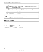
website at http://kbserver.netgear.com/main.asp. Failure to these specifications: Product Version Manual Publication Date Smart Switch June 2009 Note: Product updates are available on the NETGEAR, Inc. Revision History Part Number Version Number Date 202-10510-01 1.0 June 2009 Description Initial release vi v1.0, June 2009 GS716T/GS724T Hardware Installation Guide Danger: This is written for the Smart Switch according to take heed of this notice may result in personal injury or death. • Scope. This manual is a safety warning.
website at http://kbserver.netgear.com/main.asp. Failure to these specifications: Product Version Manual Publication Date Smart Switch June 2009 Note: Product updates are available on the NETGEAR, Inc. Revision History Part Number Version Number Date 202-10510-01 1.0 June 2009 Description Initial release vi v1.0, June 2009 GS716T/GS724T Hardware Installation Guide Danger: This is written for the Smart Switch according to take heed of this notice may result in personal injury or death. • Scope. This manual is a safety warning.
GS716Tv2/GS724Tv3 Hardware manual
Page 18
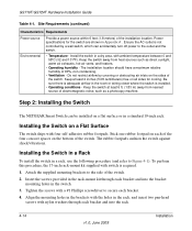
... specifications for cooling. Install the switch in a dry area, with a #1 Phillips screwdriver to Figure 4-1). Step 2: Installing the Switch The NETGEAR Smart Switch can accidentally turn off power to the side of 90%, non-condensing. • Ventilation - Stick one rubber footpad on each bracket. 4. To perform this procedure, the 17-inch rack-mount kit supplied with switch...
... specifications for cooling. Install the switch in a dry area, with a #1 Phillips screwdriver to Figure 4-1). Step 2: Installing the Switch The NETGEAR Smart Switch can accidentally turn off power to the side of 90%, non-condensing. • Ventilation - Stick one rubber footpad on each bracket. 4. To perform this procedure, the 17-inch rack-mount kit supplied with switch...

GS716Tv2/GS724Tv3 Hardware manual
Page 20
... how to connect PCs to the switch's RJ-45 ports. Figure 4-2 Connect each PC to 100 m (328 ft.). Note: Ethernet specifications limit the cable length between the switch and the attached device to an RJ-45 network port on the Switch front panel (Figure 4-2 ). Standard... connections. GS716T/GS724T Hardware Installation Guide Step 4: Connecting Devices to the Switch The following procedure describes how to install an SFP Gigabit Ethernet module in the switch's Gigabit module bay. To install an SFP GBIC module: 4-16 v1.0, June 2009 Installation The NETGEAR Smart Switch contains Auto...
... how to connect PCs to the switch's RJ-45 ports. Figure 4-2 Connect each PC to 100 m (328 ft.). Note: Ethernet specifications limit the cable length between the switch and the attached device to an RJ-45 network port on the Switch front panel (Figure 4-2 ). Standard... connections. GS716T/GS724T Hardware Installation Guide Step 4: Connecting Devices to the Switch The following procedure describes how to install an SFP Gigabit Ethernet module in the switch's Gigabit module bay. To install an SFP GBIC module: 4-16 v1.0, June 2009 Installation The NETGEAR Smart Switch contains Auto...
GS716Tv2/GS724Tv3 Hardware manual
Page 23
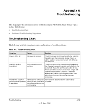
...and locked into the port at the switch and the connected device. Check the crimp on the switch and the connected device are functioning. Appendix A Troubleshooting This chapter provides information about troubleshooting the NETGEAR Smart Switch. Troubleshooting v1.0, June 2009 A-19 ...Check the power cord connections for a defective adapter card, cable, or port by testing them in an alternate environment where all cables used are correct and comply with Ethernet specifications. Check for the switch at both the switch...
...and locked into the port at the switch and the connected device. Check the crimp on the switch and the connected device are functioning. Appendix A Troubleshooting This chapter provides information about troubleshooting the NETGEAR Smart Switch. Troubleshooting v1.0, June 2009 A-19 ...Check the power cord connections for a defective adapter card, cable, or port by testing them in an alternate environment where all cables used are correct and comply with Ethernet specifications. Check for the switch at both the switch...
GS716Tv2/GS724Tv3 Hardware manual
Page 26
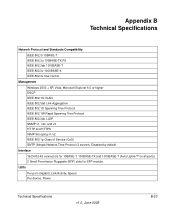
...-45 connectors for 10BASE-T, 100BASE-TX and 1000BASE-T (Auto Uplink™ on all ports). 2 Small Form-factor Pluggable (SFP) slots for SFP module. Appendix B Technical Specifications Network Protocol and Standards Compatibility IEEE 802.3i 10BASE-T IEEE 802.3u 100BASE-TX,FX IEEE 802.3ab 1000BASE-T IEEE 802.3z 1000BASE-X IEEE 802...
...-45 connectors for 10BASE-T, 100BASE-TX and 1000BASE-T (Auto Uplink™ on all ports). 2 Small Form-factor Pluggable (SFP) slots for SFP module. Appendix B Technical Specifications Network Protocol and Standards Compatibility IEEE 802.3i 10BASE-T IEEE 802.3u 100BASE-TX,FX IEEE 802.3ab 1000BASE-T IEEE 802.3z 1000BASE-X IEEE 802...
GS716Tv2/GS724Tv3 Hardware manual
Page 27
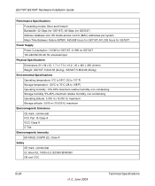
...MTBF): 465,998 hours for GS716T; 401,205 hours for GS724T Power Supply Power Consumption: 16.5W for GS716T, 21.5W for GS724T 100-240VAC/50-60 Hz universal input Physical Specifications Dimensions (H x W x D): 1.7 x 17.3 x 10.2 / 43 x 440 x 260 (in/mm) Weight: GS716T: 5.64/2.56 (lbs/kg),... GS724T: 5.86/2.66 (lbs/kg) Environmental Specifications Operating temperature: 0°C to ...
...MTBF): 465,998 hours for GS716T; 401,205 hours for GS724T Power Supply Power Consumption: 16.5W for GS716T, 21.5W for GS724T 100-240VAC/50-60 Hz universal input Physical Specifications Dimensions (H x W x D): 1.7 x 17.3 x 10.2 / 43 x 440 x 260 (in/mm) Weight: GS716T: 5.64/2.56 (lbs/kg),... GS724T: 5.86/2.66 (lbs/kg) Environmental Specifications Operating temperature: 0°C to ...
GS716Tv2/GS724Tv3 Hardware manual
Page 28
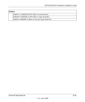
GS716T/GS724T Hardware Installation Guide Modules AGM731F 1000BASE-SX SFP GBIC for multimode fiber AGM732F 1000BASE-LX SFP GBIC for single mode fiber AGM733 1000BASE-LZ GBIC for long haul single mode fiber Technical Specifications v1.0, June 2009 B-25
GS716T/GS724T Hardware Installation Guide Modules AGM731F 1000BASE-SX SFP GBIC for multimode fiber AGM732F 1000BASE-LX SFP GBIC for single mode fiber AGM733 1000BASE-LZ GBIC for long haul single mode fiber Technical Specifications v1.0, June 2009 B-25
GS716T Hardware manual
Page 3
... the Installation...15 Step 4: Connecting Devices to the Switch...15 Step 5: Installing a SFP GBIC Module ...15 Step 6: Applying AC Power ...16 Step 7: Switch Management through a Web Browser or Utility Program (Initial Configuration 16 APPENDIX A: GLOSSARY ...17 APPENDIX B: TROUBLESHOOTING ...19 Troubleshooting Chart ...19 Additional Troubleshooting Suggestions ...19 APPENDIX C: TECHNICAL SPECIFICATIONS...20 Page 3 of 20
... the Installation...15 Step 4: Connecting Devices to the Switch...15 Step 5: Installing a SFP GBIC Module ...15 Step 6: Applying AC Power ...16 Step 7: Switch Management through a Web Browser or Utility Program (Initial Configuration 16 APPENDIX A: GLOSSARY ...17 APPENDIX B: TROUBLESHOOTING ...19 Troubleshooting Chart ...19 Additional Troubleshooting Suggestions ...19 APPENDIX C: TECHNICAL SPECIFICATIONS...20 Page 3 of 20