GS716Tv2/GS724Tv3 Hardware manual
Page 1
GS716T/GS724T Hardware Installation Guide NETGEAR, Inc. 350 East Plumeria Drive San Jose, California 95134 USA 202-10510-01 June 2009 v1.0
GS716T/GS724T Hardware Installation Guide NETGEAR, Inc. 350 East Plumeria Drive San Jose, California 95134 USA 202-10510-01 June 2009 v1.0
GS716Tv2/GS724Tv3 Hardware manual
Page 2
...Inc. NETGEAR does not assume any liability that the Smart Switch has been... document without notice. Trademarks NETGEAR, the NETGEAR logo, and Auto Uplink are registered trademarks of NETGEAR, Inc. Statement of Conditions...improving internal design, operational function, and/or reliability, NETGEAR reserves the right to make changes to the notes ...herein. All rights reserved. © 2007, 2008, 2009 by NETGEAR, Inc. Microsoft, Windows, and Windows NT are trademarks or ...GS716T and GS724T June 2009 GS716T/GS724T Series Smart Switch Smart Switch Business English 202-10510-01 1.0 ii...
...Inc. NETGEAR does not assume any liability that the Smart Switch has been... document without notice. Trademarks NETGEAR, the NETGEAR logo, and Auto Uplink are registered trademarks of NETGEAR, Inc. Statement of Conditions...improving internal design, operational function, and/or reliability, NETGEAR reserves the right to make changes to the notes ...herein. All rights reserved. © 2007, 2008, 2009 by NETGEAR, Inc. Microsoft, Windows, and Windows NT are trademarks or ...GS716T and GS724T June 2009 GS716T/GS724T Series Smart Switch Smart Switch Business English 202-10510-01 1.0 ii...
GS716Tv2/GS724Tv3 Hardware manual
Page 3
... and Scope v Revision History ...vi Chapter 1 Introduction Overview ...1-1 Features ...1-2 Package Contents ...1-3 Chapter 2 Physical Description GS716T Front and Back Panel Configuration 2-5 GS724T Front and Back Panel Configuration 2-6 LED Designations ...2-7 Port LEDs ...2-7 System LEDs... ...2-8 SFP GBIC Module ...2-9 Factory Defaults Button 2-9 Chapter 3 Applications Desktop Switching ...3-11 Chapter 4 Installation Step 1: Preparing the Site 4-13 Step 2: Installing the Switch 4-14 Installing the Switch on a Flat Surface 4-14 Installing the Switch in a Rack 4-14 iii v1.0, June 2009
... and Scope v Revision History ...vi Chapter 1 Introduction Overview ...1-1 Features ...1-2 Package Contents ...1-3 Chapter 2 Physical Description GS716T Front and Back Panel Configuration 2-5 GS724T Front and Back Panel Configuration 2-6 LED Designations ...2-7 Port LEDs ...2-7 System LEDs... ...2-8 SFP GBIC Module ...2-9 Factory Defaults Button 2-9 Chapter 3 Applications Desktop Switching ...3-11 Chapter 4 Installation Step 1: Preparing the Site 4-13 Step 2: Installing the Switch 4-14 Installing the Switch on a Flat Surface 4-14 Installing the Switch in a Rack 4-14 iii v1.0, June 2009
GS716Tv2/GS724Tv3 Hardware manual
Page 4
GS716T/GS724T Hardware Installation Guide Step 3: Checking the Installation 4-15 Step 4: Connecting Devices to the Switch 4-16 Step 5: Installing an SFP GBIC Module 4-16 Step 6: Applying AC Power 4-17 Step 7: Managing the Switch using a Web Browser or the PC Utility 4-18 Appendix A Troubleshooting Troubleshooting Chart A-19 Additional Troubleshooting Suggestions A-20 Network Adapter Cards A-20 Configuration ...A-20 Switch Integrity ...A-20 Auto-Negotiation A-21 Appendix B Technical Specifications Index iv v1.0, June 2009
GS716T/GS724T Hardware Installation Guide Step 3: Checking the Installation 4-15 Step 4: Connecting Devices to the Switch 4-16 Step 5: Installing an SFP GBIC Module 4-16 Step 6: Applying AC Power 4-17 Step 7: Managing the Switch using a Web Browser or the PC Utility 4-18 Appendix A Troubleshooting Troubleshooting Chart A-19 Additional Troubleshooting Suggestions A-20 Network Adapter Cards A-20 Configuration ...A-20 Switch Integrity ...A-20 Auto-Negotiation A-21 Appendix B Technical Specifications Index iv v1.0, June 2009

GS716Tv2/GS724Tv3 Hardware manual
Page 5
... Warning: Ignoring this manual is used to highlight information of note may result in a malfunction or damage to install, configure and troubleshoot the Smart Switch. v v1.0, June 2009 This manual uses the following typographical conventions: Italic Bold Fixed italic Emphasis, books, CDs, file and server names, extensions User input,... to highlight special messages: Note: This format is intended for readers with intermediate computer and Internet skills. About This Manual The NETGEAR® ProSafeTM GS716T/GS724T Hardware Installation Guide describes how to the equipment.
... Warning: Ignoring this manual is used to highlight information of note may result in a malfunction or damage to install, configure and troubleshoot the Smart Switch. v v1.0, June 2009 This manual uses the following typographical conventions: Italic Bold Fixed italic Emphasis, books, CDs, file and server names, extensions User input,... to highlight special messages: Note: This format is intended for readers with intermediate computer and Internet skills. About This Manual The NETGEAR® ProSafeTM GS716T/GS724T Hardware Installation Guide describes how to the equipment.
GS716Tv2/GS724Tv3 Hardware manual
Page 6
website at http://kbserver.netgear.com/main.asp. Failure to these specifications: Product Version Manual Publication Date Smart Switch June 2009 Note: Product updates are available on the NETGEAR, Inc. Revision History Part Number Version Number Date 202-10510-01 1.0 June 2009 Description Initial release vi v1.0, June 2009 GS716T/GS724T Hardware Installation Guide Danger: This is written for the Smart Switch according to take heed of this notice may result in personal injury or death. • Scope. This manual is a safety warning.
website at http://kbserver.netgear.com/main.asp. Failure to these specifications: Product Version Manual Publication Date Smart Switch June 2009 Note: Product updates are available on the NETGEAR, Inc. Revision History Part Number Version Number Date 202-10510-01 1.0 June 2009 Description Initial release vi v1.0, June 2009 GS716T/GS724T Hardware Installation Guide Danger: This is written for the Smart Switch according to take heed of this notice may result in personal injury or death. • Scope. This manual is a safety warning.
GS716Tv2/GS724Tv3 Hardware manual
Page 7
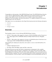
... which support 1000 (1000BASE-SX/LX)/100 Mbps SFP. The NETGEAR Smart Switch is for the observation, configuration, and control of 1-1 v1.0, June 2009 With a Webbased Graphical User Interface (GUI), the switch's many capabilities can be viewed and used in a simple and... with a complete package of features for the following NETGEAR Smart Switches: • GS716T - The switch's management features include configuration for port and switch information, VLAN for traffic control, port trunking for use out of the NETGEAR Smart Switch. For example: • Linking to a server or...
... which support 1000 (1000BASE-SX/LX)/100 Mbps SFP. The NETGEAR Smart Switch is for the observation, configuration, and control of 1-1 v1.0, June 2009 With a Webbased Graphical User Interface (GUI), the switch's many capabilities can be viewed and used in a simple and... with a complete package of features for the following NETGEAR Smart Switches: • GS716T - The switch's management features include configuration for port and switch information, VLAN for traffic control, port trunking for use out of the NETGEAR Smart Switch. For example: • Linking to a server or...
GS716Tv2/GS724Tv3 Hardware manual
Page 8
... all ports to make the right connection. 1-2 Introduction v1.0, June 2009 The RJ-45 copper ports corresponding to the...are supported: • 1000BASE-SX • 1000BASE-LX • 100BASE-FX • The devices support full NETGEAR Smart Switch functionality. • The devices provide full compatibility with IEEE standards: • IEEE 802.3i, (10BASE-T) ... two physical connections, SFP fiber and RJ-45 copper. GS716T/GS724T Hardware Installation Guide Service (CoS) for high-speed networking. The Smart Switch can automatically negotiate to the Combo ports are connected. Features...
... all ports to make the right connection. 1-2 Introduction v1.0, June 2009 The RJ-45 copper ports corresponding to the...are supported: • 1000BASE-SX • 1000BASE-LX • 100BASE-FX • The devices support full NETGEAR Smart Switch functionality. • The devices provide full compatibility with IEEE standards: • IEEE 802.3i, (10BASE-T) ... two physical connections, SFP fiber and RJ-45 copper. GS716T/GS724T Hardware Installation Guide Service (CoS) for high-speed networking. The Smart Switch can automatically negotiate to the Combo ports are connected. Features...
GS716Tv2/GS724Tv3 Hardware manual
Page 9
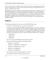
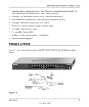
Reset PWR ® ProSafe 24 Port Gigabit Smart Switch 1 3 5 7 9 11 13 15 17 19 21 23 LINK/ACT SPD Green (1000M) Yellow (100M) FDX 2 4 6 8 10 ...14 16 18 20 22 24T 23F 24F Link/ Link/ ACT ACT MODEL GS724T Auto™ Uplink Factory Defaults Figure 1-1 Introduction 1-3 v1.0, June 2009 The table contains up to 8K Media Access Control (MAC) addresses. • Full-duplex and half-duplex functions for... rack-mountable 17-inch chassis. • Fan speed control supported. Package Contents Figure 1-1 shows the package contents of the NETGEAR GS716T and GS724T Series Smart Switch.
Reset PWR ® ProSafe 24 Port Gigabit Smart Switch 1 3 5 7 9 11 13 15 17 19 21 23 LINK/ACT SPD Green (1000M) Yellow (100M) FDX 2 4 6 8 10 ...14 16 18 20 22 24T 23F 24F Link/ Link/ ACT ACT MODEL GS724T Auto™ Uplink Factory Defaults Figure 1-1 Introduction 1-3 v1.0, June 2009 The table contains up to 8K Media Access Control (MAC) addresses. • Full-duplex and half-duplex functions for... rack-mountable 17-inch chassis. • Fan speed control supported. Package Contents Figure 1-1 shows the package contents of the NETGEAR GS716T and GS724T Series Smart Switch.
GS716Tv2/GS724Tv3 Hardware manual
Page 10
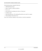
GS716T/GS724T Hardware Installation Guide Verify that the package contains the following: • NETGEAR Smart Switch • Rubber footpads for tabletop installation • Power cord • Rack-mount kit for installing the switch in a 19-inch rack • Installation guide • Smart Switch Resource CD with Smart Wizard Discovery and User's manual • Warranty/Support Information Card If any item is missing or damaged, contact the place of purchase immediately. 1-4 Introduction v1.0, June 2009
GS716T/GS724T Hardware Installation Guide Verify that the package contains the following: • NETGEAR Smart Switch • Rubber footpads for tabletop installation • Power cord • Rack-mount kit for installing the switch in a 19-inch rack • Installation guide • Smart Switch Resource CD with Smart Wizard Discovery and User's manual • Warranty/Support Information Card If any item is missing or damaged, contact the place of purchase immediately. 1-4 Introduction v1.0, June 2009

GS716Tv2/GS724Tv3 Hardware manual
Page 11
... of sensing the line speed and negotiating the operation duplex mode with the link partner automatically Figure 2-1 illustrates the NETGEAR GS716T Smart Switch front panel: System LEDs Reset PWR ® ProSafe 16 Port Gigabit Smart Switch 1 3 5 7 9 11 13 15 LINK/ACT SPD Green (1000M) Yellow (100M) FDX 2 4... Recessed default reset button to restore the device back to the factory defaults. • Port LEDs 2-5 v1.0, June 2009 Chapter 2 Physical Description This chapter describes the NETGEAR Smart Switch hardware features. Every RJ-45 port is a 24-port 10/100/1000 Mbps + 2 SFP Combo ports...
... of sensing the line speed and negotiating the operation duplex mode with the link partner automatically Figure 2-1 illustrates the NETGEAR GS716T Smart Switch front panel: System LEDs Reset PWR ® ProSafe 16 Port Gigabit Smart Switch 1 3 5 7 9 11 13 15 LINK/ACT SPD Green (1000M) Yellow (100M) FDX 2 4... Recessed default reset button to restore the device back to the factory defaults. • Port LEDs 2-5 v1.0, June 2009 Chapter 2 Physical Description This chapter describes the NETGEAR Smart Switch hardware features. Every RJ-45 port is a 24-port 10/100/1000 Mbps + 2 SFP Combo ports...
GS716Tv2/GS724Tv3 Hardware manual
Page 12
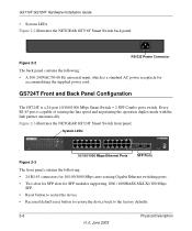
...the line speed and negotiating the operation duplex mode with the link partner automatically Figure 2-3 illustrates the NETGEAR GS724T Smart Switch front panel: System LEDs Reset PWR ® ProSafe 24 Port Gigabit Smart Switch 1 3 5 7 9 11 13 15 17 19 21 23 LINK/ACT SPD Green (1000M)... default reset button to restore the device back to the factory defaults. 2-6 Physical Description v1.0, June 2009 GS716T/GS724T Hardware Installation Guide • System LEDs Figure 2-2 illustrates the NETGEAR GS716T Smart Switch back panel: 100-240V ~ 50-60Hz Figure 2-2 RS-232 Power Connector The back...
...the line speed and negotiating the operation duplex mode with the link partner automatically Figure 2-3 illustrates the NETGEAR GS724T Smart Switch front panel: System LEDs Reset PWR ® ProSafe 24 Port Gigabit Smart Switch 1 3 5 7 9 11 13 15 17 19 21 23 LINK/ACT SPD Green (1000M)... default reset button to restore the device back to the factory defaults. 2-6 Physical Description v1.0, June 2009 GS716T/GS724T Hardware Installation Guide • System LEDs Figure 2-2 illustrates the NETGEAR GS716T Smart Switch back panel: 100-240V ~ 50-60Hz Figure 2-2 RS-232 Power Connector The back...
GS716Tv2/GS724Tv3 Hardware manual
Page 13
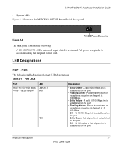
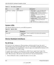
... 10/100 Mbps link is established on the port at 10/ 100 Mbps. • Off - Table 2-1. Physical Description 2-7 v1.0, June 2009 GS716T/GS724T Hardware Installation Guide • System LEDs Figure 2-4 illustrates the NETGEAR GS724T Smart Switch back panel: Figure 2-4 100-240V ~ 50-60Hz RS-232 Power Connector The back panel contains the following table...
... 10/100 Mbps link is established on the port at 10/ 100 Mbps. • Off - Table 2-1. Physical Description 2-7 v1.0, June 2009 GS716T/GS724T Hardware Installation Guide • System LEDs Figure 2-4 illustrates the NETGEAR GS724T Smart Switch back panel: Figure 2-4 100-240V ~ 50-60Hz RS-232 Power Connector The back panel contains the following table...
GS716Tv2/GS724Tv3 Hardware manual
Page 14
...UTP) cable terminated with either straight-through or crossover cable. 2-8 Physical Description v1.0, June 2009 Device Hardware Interfaces RJ-45 Ports RJ-45 ports are auto-sensing ports. This technology allows attaching devices to the switch and is a straight-through or crossover cables. System LEDs LED Power LED ...- Packets transmission or reception is established on the port at 100 Mbps. • Off - No SPD link is occurring on the port. GS716T/GS724T Hardware Installation Guide Table 2-1. Packets transmission or reception is disconnected.
...UTP) cable terminated with either straight-through or crossover cable. 2-8 Physical Description v1.0, June 2009 Device Hardware Interfaces RJ-45 Ports RJ-45 ports are auto-sensing ports. This technology allows attaching devices to the switch and is a straight-through or crossover cables. System LEDs LED Power LED ...- Packets transmission or reception is established on the port at 100 Mbps. • Off - No SPD link is occurring on the port. GS716T/GS724T Hardware Installation Guide Table 2-1. Packets transmission or reception is disconnected.
GS716Tv2/GS724Tv3 Hardware manual
Page 15
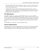
...connectors are plugged in at the same time. Factory Defaults Button The Smart Switch has a Factory Default button so that you enable the Factory Default button, ...you can be used at the same time, the fiber port will be active. GS716T/GS724T Hardware Installation Guide • Determines whether the link to the attached device ...) or an "uplink" connection (such as the AGM731F, AGM732F, or AGM733 from NETGEAR, allowing fiber connections on the network. Being a combo port, only one type of... router, switch, or hub). • Configures the RJ-45 port to its factory ...
...connectors are plugged in at the same time. Factory Defaults Button The Smart Switch has a Factory Default button so that you enable the Factory Default button, ...you can be used at the same time, the fiber port will be active. GS716T/GS724T Hardware Installation Guide • Determines whether the link to the attached device ...) or an "uplink" connection (such as the AGM731F, AGM732F, or AGM733 from NETGEAR, allowing fiber connections on the network. Being a combo port, only one type of... router, switch, or hub). • Configures the RJ-45 port to its factory ...
GS716Tv2/GS724Tv3 Hardware manual
Page 16
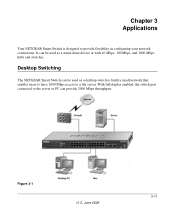
Figure 3-1 v1.0, June 2009 3-11 With full-duplex enabled, the switch port connected to the server or PC can be used as a desktop switch to build a small network that enables users to have 1000 Mbps access to provide flexibility in configuring your network connections. It can provide 2000 Mbps throughput. Desktop Switching The NETGEAR Smart Switch can be used as a stand-alone device or with 10 Mbps, 100 Mbps, and 1000 Mbps hubs and switches. Chapter 3 Applications Your NETGEAR Smart Switch is designed to a file server.
Figure 3-1 v1.0, June 2009 3-11 With full-duplex enabled, the switch port connected to the server or PC can be used as a desktop switch to build a small network that enables users to have 1000 Mbps access to provide flexibility in configuring your network connections. It can provide 2000 Mbps throughput. Desktop Switching The NETGEAR Smart Switch can be used as a stand-alone device or with 10 Mbps, 100 Mbps, and 1000 Mbps hubs and switches. Chapter 3 Applications Your NETGEAR Smart Switch is designed to a file server.
GS716Tv2/GS724Tv3 Hardware manual
Page 17
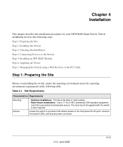
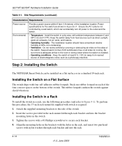
... Rack-mount installations - v1.0, June 2009 4-13 Table 4-1. Use a 17-inch (48.3-centimeter) EIA standard equipment rack that allows access to the Switch Step 5: Installing an SFP GBIC Module Step 6: Applying AC Power Step 7: Managing the Switch using a Web Browser or... installations - Chapter 4 Installation This chapter describes the installation procedures for your NETGEAR Smart Switch. Switch installation involves the following steps: Step 1: Preparing the Site Step 2: Installing the Switch Step 3: Checking the Installation Step 4: Connecting Devices to the front panel RJ...
... Rack-mount installations - v1.0, June 2009 4-13 Table 4-1. Use a 17-inch (48.3-centimeter) EIA standard equipment rack that allows access to the Switch Step 5: Installing an SFP GBIC Module Step 6: Applying AC Power Step 7: Managing the Switch using a Web Browser or... installations - Chapter 4 Installation This chapter describes the installation procedures for your NETGEAR Smart Switch. Switch installation involves the following steps: Step 1: Preparing the Site Step 2: Installing the Switch Step 3: Checking the Installation Step 4: Connecting Devices to the front panel RJ...
GS716Tv2/GS724Tv3 Hardware manual
Page 18
.... • Ventilation - GS716T/GS724T Hardware Installation Guide Table 4-1. Ensure the AC outlet is not controlled by covering or obstructing air inlets on each bracket and into the bracket mounting holes in the room or wiring closet where the switch is installed. • ...bracket. 4. Be sure there is required. 1. Step 2: Installing the Switch The NETGEAR Smart Switch can accidentally turn off power to secure each bracket and into the rack. 4-14 v1.0, June 2009 Installation Install the switch in a dry area, with a #1 Phillips screwdriver to the outlet and...
.... • Ventilation - GS716T/GS724T Hardware Installation Guide Table 4-1. Ensure the AC outlet is not controlled by covering or obstructing air inlets on each bracket and into the bracket mounting holes in the room or wiring closet where the switch is installed. • ...bracket. 4. Be sure there is required. 1. Step 2: Installing the Switch The NETGEAR Smart Switch can accidentally turn off power to secure each bracket and into the rack. 4-14 v1.0, June 2009 Installation Install the switch in a dry area, with a #1 Phillips screwdriver to the outlet and...
GS716Tv2/GS724Tv3 Hardware manual
Page 19
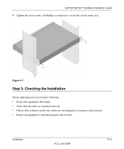
Tighten the screws with a #2 Phillips screwdriver to make sure cables are not damaged or creating a safety hazard. • Ensure all cables are installed correctly. • Check cable routing to secure the switch in the rack. Installation v1.0, June 2009 4-15 Figure 4-1 Step 3: Checking the Installation Before applying power perform the following: • Inspect the equipment thoroughly. • Verify that all equipment is mounted properly and securely. GS716T/GS724T Hardware Installation Guide 5.
Tighten the screws with a #2 Phillips screwdriver to make sure cables are not damaged or creating a safety hazard. • Ensure all cables are installed correctly. • Check cable routing to secure the switch in the rack. Installation v1.0, June 2009 4-15 Figure 4-1 Step 3: Checking the Installation Before applying power perform the following: • Inspect the equipment thoroughly. • Verify that all equipment is mounted properly and securely. GS716T/GS724T Hardware Installation Guide 5.

GS716Tv2/GS724Tv3 Hardware manual
Page 20
... to connect PCs to the switch's RJ-45 ports. If an SFP GBIC module is not being installed at this time, skip this procedure. To install an SFP GBIC module: 4-16 v1.0, June 2009 Installation GS716T/GS724T Hardware Installation Guide Step ...4: Connecting Devices to the Switch The following procedure describes how to install an SFP Gigabit Ethernet module in the switch's Gigabit module bay. Figure 4-2 Connect each PC to an RJ-45 network port on the Switch front panel (Figure 4-2 ). The NETGEAR Smart Switch...
... to connect PCs to the switch's RJ-45 ports. If an SFP GBIC module is not being installed at this time, skip this procedure. To install an SFP GBIC module: 4-16 v1.0, June 2009 Installation GS716T/GS724T Hardware Installation Guide Step ...4: Connecting Devices to the Switch The following procedure describes how to install an SFP Gigabit Ethernet module in the switch's Gigabit module bay. Figure 4-2 Connect each PC to an RJ-45 network port on the Switch front panel (Figure 4-2 ). The NETGEAR Smart Switch...
