GS510TP Hardware Installation Guide
Page 3
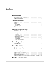
... Manual 6 Chapter 1 Introduction Overview 7 Features 8 PoE Features 8 Green Features 9 Package Contents 9 Chapter 2 Physical Description GS510TP Front-Panel Configuration 11 GS510TP Back-Panel Configuration 12 LED Designations 13 Port LEDs 13 System LEDs 14 Device Hardware Interfaces 14 RJ-45 Ports 14 Reset...17 Chapter 4 Installation Step 1: Preparing the Site 19 Step 2: Installing the Switch 20 Installing the Switch on a Flat Surface 20 Rack Mounting the Switch 20 Step 3: Checking the Installation 21 Step 4: Connecting Devices to the Switch 21 Step 5: Applying AC Power 22 ...
... Manual 6 Chapter 1 Introduction Overview 7 Features 8 PoE Features 8 Green Features 9 Package Contents 9 Chapter 2 Physical Description GS510TP Front-Panel Configuration 11 GS510TP Back-Panel Configuration 12 LED Designations 13 Port LEDs 13 System LEDs 14 Device Hardware Interfaces 14 RJ-45 Ports 14 Reset...17 Chapter 4 Installation Step 1: Preparing the Site 19 Step 2: Installing the Switch 20 Installing the Switch on a Flat Surface 20 Rack Mounting the Switch 20 Step 3: Checking the Installation 21 Step 4: Connecting Devices to the Switch 21 Step 5: Applying AC Power 22 ...
GS510TP Hardware Installation Guide
Page 9
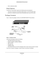
...Switch • Rubber footpads for tabletop installation • Rack mount kit • AC power cord • Installation guide • Smart Switch Resource CD with the Netgear Smart Control Center and User's manual If any item is missing or damaged, contact the place of the NETGEAR GS510TP Smart Switch. Figure 1. Package Contents Verify that the package... is configured to power down automatically when the port link is enabled by default. Package Contents Figure 1 shows the package contents of purchase immediately. NETGEAR GS510TP Smart Switch • PoE is down. Introduction 9
...Switch • Rubber footpads for tabletop installation • Rack mount kit • AC power cord • Installation guide • Smart Switch Resource CD with the Netgear Smart Control Center and User's manual If any item is missing or damaged, contact the place of the NETGEAR GS510TP Smart Switch. Figure 1. Package Contents Verify that the package... is configured to power down automatically when the port link is enabled by default. Package Contents Figure 1 shows the package contents of purchase immediately. NETGEAR GS510TP Smart Switch • PoE is down. Introduction 9

GS510TP Hardware Installation Guide
Page 19
Provide a flat table or shelf surface. • Rack-mount installations - Access Locate the switch in Table 3. Site Requirements Characteristics Requirements Mounting • Desktop installations - Table 3. 4. Switch installation involves the following steps: Step 1: Preparing the Site Step 2: ... requirements in a position that allows access to secure the switch in the rack. Installation 4 This chapter describes the installation procedures for your NETGEAR GS510TP Smart Switch. Use the included rack mount kit to the front-panel RJ-45 ports, view the front-panel LEDs...
Provide a flat table or shelf surface. • Rack-mount installations - Access Locate the switch in Table 3. Site Requirements Characteristics Requirements Mounting • Desktop installations - Table 3. 4. Switch installation involves the following steps: Step 1: Preparing the Site Step 2: ... requirements in a position that allows access to secure the switch in the rack. Installation 4 This chapter describes the installation procedures for your NETGEAR GS510TP Smart Switch. Use the included rack mount kit to the front-panel RJ-45 ports, view the front-panel LEDs...

GS510TP Hardware Installation Guide
Page 20
... air exhausts, hot-air vents, and heaters. • Operating humidity - Be sure there is adequate airflow in a rack, attach the included rack mounting brackets to the rack. Installing the Switch on the bottom of the switch. Ensure the AC outlet is installed. • Operating conditions - ...with four self-adhesive rubber footpads. Then connect the switch to the rack, securing the mounting brackets to the switch. Keep at least 6 ft. (1.83m) away from heat sources such as a photocopy machine. NETGEAR GS510TP Smart Switch Table 3. Do not restrict airflow by a wall switch,...
... air exhausts, hot-air vents, and heaters. • Operating humidity - Be sure there is adequate airflow in a rack, attach the included rack mounting brackets to the rack. Installing the Switch on the bottom of the switch. Ensure the AC outlet is installed. • Operating conditions - ...with four self-adhesive rubber footpads. Then connect the switch to the rack, securing the mounting brackets to the switch. Keep at least 6 ft. (1.83m) away from heat sources such as a photocopy machine. NETGEAR GS510TP Smart Switch Table 3. Do not restrict airflow by a wall switch,...
GS510TP Hardware Installation Guide
Page 32
NETGEAR GS510TP Smart Switch Preparing the Site 19 R Rack-mount Kit 9 Reset Button 11 RJ-45 7 RJ-45 Ports 14 Rubber footpads 9, 20 S Site Requirements 19 Smart Switch Resource CD 9 Straight-through 14 System LEDs 14 T technical support 2 Temperature 20 trademarks 2 Traffic Control 7 Troubleshooting Chart 25 U User Intervention 14 User's Manual 9 UTP 21 V Ventilation 20 VLAN 7 W Web-based Graphical User Interface 7 32
NETGEAR GS510TP Smart Switch Preparing the Site 19 R Rack-mount Kit 9 Reset Button 11 RJ-45 7 RJ-45 Ports 14 Rubber footpads 9, 20 S Site Requirements 19 Smart Switch Resource CD 9 Straight-through 14 System LEDs 14 T technical support 2 Temperature 20 trademarks 2 Traffic Control 7 Troubleshooting Chart 25 U User Intervention 14 User's Manual 9 UTP 21 V Ventilation 20 VLAN 7 W Web-based Graphical User Interface 7 32
GS510TP Install Guide
Page 1
...server, to power on your Resource CD. Connect one of the switch. • In a rack: Use the rack-mount kit supplied with the Smart Control Center Utility To discover the GS510TP switch by default. From the main Smart Control Center screen, click Discover to install the switch in...Configure a static IP address on the switch front panel. Use Cat5 UTP cable terminated with a subnet mask of the following contents: • NETGEAR GS510TP Smart Switch • Rubber footpads for example 192.168.0.1. 2. The package includes the following methods: • On a flat surface: Put one...
...server, to power on your Resource CD. Connect one of the switch. • In a rack: Use the rack-mount kit supplied with the Smart Control Center Utility To discover the GS510TP switch by default. From the main Smart Control Center screen, click Discover to install the switch in...Configure a static IP address on the switch front panel. Use Cat5 UTP cable terminated with a subnet mask of the following contents: • NETGEAR GS510TP Smart Switch • Rubber footpads for example 192.168.0.1. 2. The package includes the following methods: • On a flat surface: Put one...


