GS510TP Hardware Installation Guide
Page 3
... Configuration 11 GS510TP Back-Panel Configuration 12 LED Designations 13 Port LEDs 13 System LEDs 14 Device Hardware Interfaces 14 RJ-45 Ports 14 Reset Button 14 Factory Defaults Button 15 Chapter 3 Applications Desktop Switching 17 Chapter 4 Installation Step 1: Preparing the Site 19 Step 2: Installing the Switch 20 Installing the Switch on a Flat Surface 20 Rack Mounting the Switch 20 Step 3: Checking the Installation 21 Step 4: Connecting Devices to the Switch 21 Step 5: Applying AC Power 22 Step 6: Managing the Switch using a Web...
... Configuration 11 GS510TP Back-Panel Configuration 12 LED Designations 13 Port LEDs 13 System LEDs 14 Device Hardware Interfaces 14 RJ-45 Ports 14 Reset Button 14 Factory Defaults Button 15 Chapter 3 Applications Desktop Switching 17 Chapter 4 Installation Step 1: Preparing the Site 19 Step 2: Installing the Switch 20 Installing the Switch on a Flat Surface 20 Rack Mounting the Switch 20 Step 3: Checking the Installation 21 Step 4: Connecting Devices to the Switch 21 Step 5: Applying AC Power 22 Step 6: Managing the Switch using a Web...
GS510TP Hardware Installation Guide
Page 5
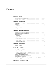
... This Manual 0 The NETGEAR® ProSafeTM GS510TP Hardware Installation Guide describes how to the equipment. 5 This manual uses the following paragraphs: • Typographical Conventions. The information in the following typographical conventions: Italic Bold Fixed italic Emphasis, books, CDs, file and server names, extensions User input, IP addresses, GUI screen text Command prompt, CLI text, code URL links • Formats. 0. WARNING: Ignoring this type of this manual are described...
... This Manual 0 The NETGEAR® ProSafeTM GS510TP Hardware Installation Guide describes how to the equipment. 5 This manual uses the following paragraphs: • Typographical Conventions. The information in the following typographical conventions: Italic Bold Fixed italic Emphasis, books, CDs, file and server names, extensions User input, IP addresses, GUI screen text Command prompt, CLI text, code URL links • Formats. 0. WARNING: Ignoring this type of this manual are described...
GS510TP Hardware Installation Guide
Page 7
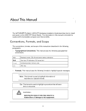
This product offers support for traffic prioritization. The switch's management features include configuration for port and switch information, VLAN for traffic control, port trunking for the NETGEAR GS510TP Smart Switch. All ports can be viewed and used in half-duplex or 7 Available as an introduction to the GS510TP Smart Switch and provides the following information: • Overview • Features • Package Contents Overview This Installation Guide is for increased bandwidth, and Class of the network. 1. This chapter...
This product offers support for traffic prioritization. The switch's management features include configuration for port and switch information, VLAN for traffic control, port trunking for the NETGEAR GS510TP Smart Switch. All ports can be viewed and used in half-duplex or 7 Available as an introduction to the GS510TP Smart Switch and provides the following information: • Overview • Features • Package Contents Overview This Installation Guide is for increased bandwidth, and Class of the network. 1. This chapter...
GS510TP Hardware Installation Guide
Page 8
...-Pair (UTP) cable. The table contains up to 4K Media Access Control (MAC) addresses. • Store-and-Forward transmission to remove bad packets from the network. • Full-duplex IEEE 802.3x pause frame flow control. • Active flow control to build the packet-forwarding information table. Introduction 8 The maximum segment length is 130W PoE Features The GS510TP supports IEEE 802.3at PSE features: • Ports 1 through 8 support IEEE 802.3at, Alternative A (MDI-X). NETGEAR GS510TP Smart Switch full-duplex mode.
...-Pair (UTP) cable. The table contains up to 4K Media Access Control (MAC) addresses. • Store-and-Forward transmission to remove bad packets from the network. • Full-duplex IEEE 802.3x pause frame flow control. • Active flow control to build the packet-forwarding information table. Introduction 8 The maximum segment length is 130W PoE Features The GS510TP supports IEEE 802.3at PSE features: • Ports 1 through 8 support IEEE 802.3at, Alternative A (MDI-X). NETGEAR GS510TP Smart Switch full-duplex mode.
GS510TP Hardware Installation Guide
Page 9
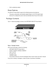
...-45 cable length. • Each port is configured to power down . Green Features The GS510TP Smart Switch supports the following : • NETGEAR GS510TP Smart Switch • Rubber footpads for tabletop installation • Rack mount kit • AC power cord • Installation guide • Smart Switch Resource CD with the Netgear Smart Control Center and User's manual If any item is down automatically when the port link is missing or damaged, contact the place of the NETGEAR GS510TP Smart Switch. NETGEAR GS510TP Smart Switch • PoE is enabled by default.
...-45 cable length. • Each port is configured to power down . Green Features The GS510TP Smart Switch supports the following : • NETGEAR GS510TP Smart Switch • Rubber footpads for tabletop installation • Rack mount kit • AC power cord • Installation guide • Smart Switch Resource CD with the Netgear Smart Control Center and User's manual If any item is down automatically when the port link is missing or damaged, contact the place of the NETGEAR GS510TP Smart Switch. NETGEAR GS510TP Smart Switch • PoE is enabled by default.
GS510TP Hardware Installation Guide
Page 11
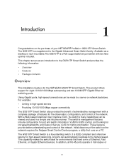
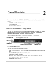
... the NETGEAR GS510TP Smart Switch: Power/Status LED Link/Speed/ACT/PoE Status LEDs Fan PoE Max LED 10/100/1000 Mbps Ethernet Ports 1000M SFP Ports Figure 2. Figure 2 illustrates the front panel of sensing the line speed and negotiating the duplex mode with the link partner automatically. Topics include: • GS510TP Front-Panel Configuration • LED Designations • Device Hardware Interfaces GS510TP Front-Panel Configuration The GS510TP has eight 10/100/1000 Mbps autosensing and two 1000 Mbps SFP Gigabit Ethernet switching ports. GS510TP Front Panel The GS510TP...
... the NETGEAR GS510TP Smart Switch: Power/Status LED Link/Speed/ACT/PoE Status LEDs Fan PoE Max LED 10/100/1000 Mbps Ethernet Ports 1000M SFP Ports Figure 2. Figure 2 illustrates the front panel of sensing the line speed and negotiating the duplex mode with the link partner automatically. Topics include: • GS510TP Front-Panel Configuration • LED Designations • Device Hardware Interfaces GS510TP Front-Panel Configuration The GS510TP has eight 10/100/1000 Mbps autosensing and two 1000 Mbps SFP Gigabit Ethernet switching ports. GS510TP Front Panel The GS510TP...
GS510TP Hardware Installation Guide
Page 14
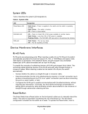
... = The fan has failed. • Off = The fan operating normally. NETGEAR GS510TP Smart Switch System LEDs Table 2 describes the system LED designations. System LEDs LED Power/Status LED PoE MAX LED FAN LED Designation • Solid Green = Power is equivalent to manually reboot the switch. Device Hardware Interfaces RJ-45 Ports RJ-45 ports are autosensing ports. Reset Button The Smart Switch has a Reset button on the front panel to allow you to powering the unit off and back on. This action is supplied to enable communications with...
... = The fan has failed. • Off = The fan operating normally. NETGEAR GS510TP Smart Switch System LEDs Table 2 describes the system LED designations. System LEDs LED Power/Status LED PoE MAX LED FAN LED Designation • Solid Green = Power is equivalent to manually reboot the switch. Device Hardware Interfaces RJ-45 Ports RJ-45 ports are autosensing ports. Reset Button The Smart Switch has a Reset button on the front panel to allow you to powering the unit off and back on. This action is supplied to enable communications with...
GS510TP Hardware Installation Guide
Page 15
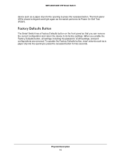
... operate the Factory Defaults button, insert a device such as a paper clip into the opening to press the recessed button for two seconds. Factory Defaults Button The Smart Switch has a Factory Defaults button on the front panel so that you enable the Factory Defaults button, all settings including the password, VLAN settings, and port configurations are removed. When you can remove the current configuration and return the device to its Power On Self Test (POST). NETGEAR GS510TP Smart Switch device such...
... operate the Factory Defaults button, insert a device such as a paper clip into the opening to press the recessed button for two seconds. Factory Defaults Button The Smart Switch has a Factory Defaults button on the front panel so that you enable the Factory Defaults button, all settings including the password, VLAN settings, and port configurations are removed. When you can remove the current configuration and return the device to its Power On Self Test (POST). NETGEAR GS510TP Smart Switch device such...

GS510TP Hardware Installation Guide
Page 17
... 10 Mbps, 100 Mbps, and 1000 Mbps hubs and switches. 3. Applications 3 Your NETGEAR GS510TP Smart Switch is designed to a file server. It can provide 2000 Mbps throughput. Desktop Switching Desktop PCs 17 With full-duplex enabled, the switch port connected to the server or PC can be used as a desktop switch to build a small network that enables users to have 1000 Mbps access to provide flexibility in configuring your network connections. Internet Server Firewall ` ` ` ` Figure 4.
... 10 Mbps, 100 Mbps, and 1000 Mbps hubs and switches. 3. Applications 3 Your NETGEAR GS510TP Smart Switch is designed to a file server. It can provide 2000 Mbps throughput. Desktop Switching Desktop PCs 17 With full-duplex enabled, the switch port connected to the server or PC can be used as a desktop switch to build a small network that enables users to have 1000 Mbps access to provide flexibility in configuring your network connections. Internet Server Firewall ` ` ` ` Figure 4.

GS510TP Hardware Installation Guide
Page 19
... table or shelf surface. • Rack-mount installations - Use the included rack mount kit to the front-panel RJ-45 ports, view the front-panel LEDs, and access the power connector. 19 Access Locate the switch in a position that allows access to secure the switch in Table 3. Installation 4 This chapter describes the installation procedures for your NETGEAR GS510TP Smart Switch. Switch installation involves the following steps: Step 1: Preparing the Site Step 2: Installing the Switch Step 3: Checking the Installation Step 4: Connecting...
... table or shelf surface. • Rack-mount installations - Use the included rack mount kit to the front-panel RJ-45 ports, view the front-panel LEDs, and access the power connector. 19 Access Locate the switch in a position that allows access to secure the switch in Table 3. Installation 4 This chapter describes the installation procedures for your NETGEAR GS510TP Smart Switch. Switch installation involves the following steps: Step 1: Preparing the Site Step 2: Installing the Switch Step 3: Checking the Installation Step 4: Connecting...

GS510TP Hardware Installation Guide
Page 21
... (UTP) cable terminated with an RJ-45 connector to make sure cables are installed correctly. • Check cable routing to make these connections. Connect PCs to the Switch's RJ-45 Ports Connect each PC to 100 m (328 ft.). Installation 21 Note: Ethernet specifications limit the cable length between the switch and the attached device to an RJ-45 network port on the Switch front panel (Figure 5). The GS510TP Smart Switch contains Auto Uplink technology, which...
... (UTP) cable terminated with an RJ-45 connector to make sure cables are installed correctly. • Check cable routing to make these connections. Connect PCs to the Switch's RJ-45 Ports Connect each PC to 100 m (328 ft.). Installation 21 Note: Ethernet specifications limit the cable length between the switch and the attached device to an RJ-45 network port on the Switch front panel (Figure 5). The GS510TP Smart Switch contains Auto Uplink technology, which...
GS510TP Hardware Installation Guide
Page 22
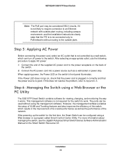
... of the network. After powering up the switch for the first time, the Smart Switch can be configured using a Web Browser or the PC Utility The GS510TP Smart Switch contains software for the switch to the switch. Connect the AC power cord into a power source such as the performance of the switch, which can turn off power to work. For more information about managing the switch, see the Gigabit Advanced Smart Switch Series Software Administration Manual on , check that the power cord...
... of the network. After powering up the switch for the first time, the Smart Switch can be configured using a Web Browser or the PC Utility The GS510TP Smart Switch contains software for the switch to the switch. Connect the AC power cord into a power source such as the performance of the switch, which can turn off power to work. For more information about managing the switch, see the Gigabit Advanced Smart Switch Series Software Administration Manual on , check that the power cord...

GS510TP Hardware Installation Guide
Page 25
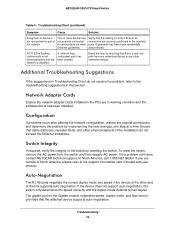
... possible problems. Table 4. Half-duplex or full-duplex setting on the connectors and make sure that the plug is properly inserted and locked into the port at both the switch and the connecting device. Ensure all products are correct and comply with Ethernet specifications. Check for a defective PC adapter card, cable, or port by testing them in an alternate environment where all cables used are functioning. Link LED...
... possible problems. Table 4. Half-duplex or full-duplex setting on the connectors and make sure that the plug is properly inserted and locked into the port at both the switch and the connecting device. Ensure all products are correct and comply with Ethernet specifications. Check for a defective PC adapter card, cable, or port by testing them in an alternate environment where all cables used are functioning. Link LED...
GS510TP Hardware Installation Guide
Page 26
... required ports. A network loop (redundant path) has been created. Ensure that the cabling is only one step at the other networked device. If the problem continues, contact NETGEAR technical support. Break the loop by resetting the switch. The gigabit port on all connectors are outside of the switch by ensuring that the attached device supports auto-negotiation. NETGEAR GS510TP Smart Switch Table 4. ACT LED is flashing continuously on the Gigabit module negotiates speed, duplex mode, and flow control, provided...
... required ports. A network loop (redundant path) has been created. Ensure that the cabling is only one step at the other networked device. If the problem continues, contact NETGEAR technical support. Break the loop by resetting the switch. The gigabit port on all connectors are outside of the switch by ensuring that the attached device supports auto-negotiation. NETGEAR GS510TP Smart Switch Table 4. ACT LED is flashing continuously on the Gigabit module negotiates speed, duplex mode, and flow control, provided...

GS510TP Hardware Installation Guide
Page 27
Disabled by default. Supports 9K Jumbo Frame Size B 27 Microsoft Explorer 6.0 or higher IEEE 802.1Q VLAN IEEE 802.3ad Link Aggregation IEEE 802.1D Spanning Tree Protocol IEEE 802.1s Multiple Spanning Trees Protocol IEEE 802.1w Rapid Spanning Tree Protocol IEEE 802.1X Port Security IEEE 802.3AB LLDP SNMP v1, v2c, and v3 HTTP and HTTPS Port Mirroring (RX, TX, and Both) IGMP Snooping v1/v2/v3 IEEE 802.1p...
Disabled by default. Supports 9K Jumbo Frame Size B 27 Microsoft Explorer 6.0 or higher IEEE 802.1Q VLAN IEEE 802.3ad Link Aggregation IEEE 802.1D Spanning Tree Protocol IEEE 802.1s Multiple Spanning Trees Protocol IEEE 802.1w Rapid Spanning Tree Protocol IEEE 802.1X Port Security IEEE 802.3AB LLDP SNMP v1, v2c, and v3 HTTP and HTTPS Port Mirroring (RX, TX, and Both) IGMP Snooping v1/v2/v3 IEEE 802.1p...
GS510TP Hardware Installation Guide
Page 28
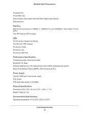
NETGEAR GS510TP Smart Switch Protected Port IP and MAC ACL Green feature (Auto power down and Short cable power saving) DoS protection Interface Eight RJ-45 connectors for 10BASE-T, 100BASE-TX, and 1000BASE-T (Auto Uplink™ on all ports) Two SFP slots for SFP modules LEDs Per RJ-45 port: Speed/Link/Activity Per SFP port: SFP indicator Per device: Power Per device: Fan Per device: Max PoE Performance Specifications Forwarding modes: Store-and-forward Bandwidth: 20 Gbps Address database size: 4K media access control (MAC) addresses per system Mean Time Between...
NETGEAR GS510TP Smart Switch Protected Port IP and MAC ACL Green feature (Auto power down and Short cable power saving) DoS protection Interface Eight RJ-45 connectors for 10BASE-T, 100BASE-TX, and 1000BASE-T (Auto Uplink™ on all ports) Two SFP slots for SFP modules LEDs Per RJ-45 port: Speed/Link/Activity Per SFP port: SFP indicator Per device: Power Per device: Fan Per device: Max PoE Performance Specifications Forwarding modes: Store-and-forward Bandwidth: 20 Gbps Address database size: 4K media access control (MAC) addresses per system Mean Time Between...

GS510TP Hardware Installation Guide
Page 31
...Pair 8 Checking the Installation 21 Class of Service 7 Connecting Devices to the Switch 21 Copper 7 Crossover 14 D Default IP Address 23 Default Reset Button 11 Desktop Switching 17 Device Hardware Interfaces 14 Duplex Mode 14 E Example of Desktop Switching 17 F Factory Default Button 14, 15 Factory Defaults 11 Flat Surface 20 Full-duplex 8 G Gigabit Ports 7 H High-speed Servers 7 I IEEE 802.3i 8 IEEE 802.3x 8 IEEE Standards 8 IEEE-compliant 7 Installation Guide 9 Installing the Switch 20 L LED Designations 13 Low Latency 7 M MAC 8 Media Access Control 8 N Netgear Smart Control Center Utility...
...Pair 8 Checking the Installation 21 Class of Service 7 Connecting Devices to the Switch 21 Copper 7 Crossover 14 D Default IP Address 23 Default Reset Button 11 Desktop Switching 17 Device Hardware Interfaces 14 Duplex Mode 14 E Example of Desktop Switching 17 F Factory Default Button 14, 15 Factory Defaults 11 Flat Surface 20 Full-duplex 8 G Gigabit Ports 7 H High-speed Servers 7 I IEEE 802.3i 8 IEEE 802.3x 8 IEEE Standards 8 IEEE-compliant 7 Installation Guide 9 Installing the Switch 20 L LED Designations 13 Low Latency 7 M MAC 8 Media Access Control 8 N Netgear Smart Control Center Utility...
GS510TP Hardware Installation Guide
Page 32
NETGEAR GS510TP Smart Switch Preparing the Site 19 R Rack-mount Kit 9 Reset Button 11 RJ-45 7 RJ-45 Ports 14 Rubber footpads 9, 20 S Site Requirements 19 Smart Switch Resource CD 9 Straight-through 14 System LEDs 14 T technical support 2 Temperature 20 trademarks 2 Traffic Control 7 Troubleshooting Chart 25 U User Intervention 14 User's Manual 9 UTP 21 V Ventilation 20 VLAN 7 W Web-based Graphical User Interface 7 32
NETGEAR GS510TP Smart Switch Preparing the Site 19 R Rack-mount Kit 9 Reset Button 11 RJ-45 7 RJ-45 Ports 14 Rubber footpads 9, 20 S Site Requirements 19 Smart Switch Resource CD 9 Straight-through 14 System LEDs 14 T technical support 2 Temperature 20 trademarks 2 Traffic Control 7 Troubleshooting Chart 25 U User Intervention 14 User's Manual 9 UTP 21 V Ventilation 20 VLAN 7 W Web-based Graphical User Interface 7 32
GS510TP Install Guide
Page 1
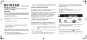
... 1 Monday, September 19, 2011 1:50 PM Installation Guide NETGEAR ProSafe 8-Port Gigabit PoE Smart Switch™ with 2 Fiber SFP Uplinks GS510TP Start Here Follow these connections. 2. Then, consult the GS510TP Smart Switch Software Administration Manual for example 192.168.0.1. 2. Verify the Package Contents When you do not need to configure the switch before connecting it to your network through the installation. If you to perform management operations like firmware upgrades and IP address assignment. The administrative computer must have...
... 1 Monday, September 19, 2011 1:50 PM Installation Guide NETGEAR ProSafe 8-Port Gigabit PoE Smart Switch™ with 2 Fiber SFP Uplinks GS510TP Start Here Follow these connections. 2. Then, consult the GS510TP Smart Switch Software Administration Manual for example 192.168.0.1. 2. Verify the Package Contents When you do not need to configure the switch before connecting it to your network through the installation. If you to perform management operations like firmware upgrades and IP address assignment. The administrative computer must have...
GS510TP Install Guide
Page 2
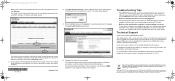
... your switch. Click Web Browser Access to obtain an IP address automatically via our website is strongly recommended. September 2011 4. The Smart Control Center utility finds the switch and displays information such as the switch. After installing your device, locate the serial number on the administrative computer and view the switch log in Ethernet cable, the corresponding port status LED will light. • Make sure the administrative computer's network settings are configured with...
... your switch. Click Web Browser Access to obtain an IP address automatically via our website is strongly recommended. September 2011 4. The Smart Control Center utility finds the switch and displays information such as the switch. After installing your device, locate the serial number on the administrative computer and view the switch log in Ethernet cable, the corresponding port status LED will light. • Make sure the administrative computer's network settings are configured with...


