
GS108T/ GS110TP Smart Switch Software Administration Manual
Page 48
... timers, and power limits to manage the power supplied to the connected PDs and to ensure that the GS110TP power budget is capable of delivering up to 15.4W of power to configure PoE SNMP trap settings. Note: You can view and configure PoE settings for the switch and for ports ... Configuration page by clicking System PoE Advanced PoE Configuration. 48 | Chapter 2: Configuring System Information GS108T and GS110TP Smart Switch Software Administration Manual PoE (GS110TP Only) Ports g1-g8 on page 52 PoE Configuration Use the PoE Configuration page to view global PoE...
... timers, and power limits to manage the power supplied to the connected PDs and to ensure that the GS110TP power budget is capable of delivering up to 15.4W of power to configure PoE SNMP trap settings. Note: You can view and configure PoE settings for the switch and for ports ... Configuration page by clicking System PoE Advanced PoE Configuration. 48 | Chapter 2: Configuring System Information GS108T and GS110TP Smart Switch Software Administration Manual PoE (GS110TP Only) Ports g1-g8 on page 52 PoE Configuration Use the PoE Configuration page to view global PoE...
GS108T/ GS110TP Smart Switch Software Administration Manual
Page 50
...detected using two collected samples. You can select multiple ports and LAGs to apply the same setting to determine which ports can supply power. Determine which is drawing from the system. The class defines the range of the PD connected to be used to the ... methods to detect PDs. • 802.3af 4point and Legacy: Select this option to all interfaces. 5. Shows the current power being delivered to configure. GS108T and GS110TP Smart Switch Software Administration Manual 3. The class is given a higher priority. • Detection Mode. By default, no timer schedules are ...
...detected using two collected samples. You can select multiple ports and LAGs to apply the same setting to determine which ports can supply power. Determine which is drawing from the system. The class defines the range of the PD connected to be used to the ... methods to detect PDs. • 802.3af 4point and Legacy: Select this option to all interfaces. 5. Shows the current power being delivered to configure. GS108T and GS110TP Smart Switch Software Administration Manual 3. The class is given a higher priority. • Detection Mode. By default, no timer schedules are ...
GS108Tv2/GS110TP Software Reference Manual
Page 54
... for the switch and for ports g1-g8. The switch performs a cable test on the GS110TP are IEEE802.3af-compliant ports. Configuration changes take effect immediately. The GS110TP can configure perport priority settings, timers, and power limits to manage the power supplied to the ...of 46W of power to all ports, regardless of reliable, uninterrupted power to ensure that the GS110TP power budget is placed in length, the port is used effectively. PoE (GS110TP Only) Ports g1-g8 on each cable connect to the switch. GS108T and GS110TP Smart Switch Software Administration Manual...
... for the switch and for ports g1-g8. The switch performs a cable test on the GS110TP are IEEE802.3af-compliant ports. Configuration changes take effect immediately. The GS110TP can configure perport priority settings, timers, and power limits to manage the power supplied to the ...of 46W of power to all ports, regardless of reliable, uninterrupted power to ensure that the GS110TP power budget is placed in length, the port is used effectively. PoE (GS110TP Only) Ports g1-g8 on each cable connect to the switch. GS108T and GS110TP Smart Switch Software Administration Manual...
GS108Tv2/GS110TP Software Reference Manual
Page 57
... PDs. • 802.3af 4point and Legacy: Select this option if only IEEE 802.3af (resistive signature) PDs need to be able to supply power to configure. Configure or view the settings: • Admin Mode. Select the detection mode to be detected. • 802.3af 2point Only:...power a PD is the default mode. • 802.3af 4point Only: Select this option if only IEEE 802.3af (resistive signature) PDs need to be detected using four collected samples. • 802.3af 2point and Legacy: Select this option to use both physical ports and LAGs, click ALL. 4. GS108T and GS110TP Smart Switch...
... PDs. • 802.3af 4point and Legacy: Select this option if only IEEE 802.3af (resistive signature) PDs need to be able to supply power to configure. Configure or view the settings: • Admin Mode. Select the detection mode to be detected. • 802.3af 2point Only:...power a PD is the default mode. • 802.3af 4point Only: Select this option if only IEEE 802.3af (resistive signature) PDs need to be detected using four collected samples. • 802.3af 2point and Legacy: Select this option to use both physical ports and LAGs, click ALL. 4. GS108T and GS110TP Smart Switch...
GS110TP Hardware Installation Guide
Page 12
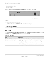
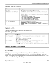
...LED Figure 2-2 illustrates the NETGEAR GS110TP Smart PoE Switch back panel. Table 2-1. Port LEDs LED Speed/Link/Activity (Left LED on the port at 10/100 Mbps. 2-2 Physical Description v1.0, March 2010 There are two LEDs for the supplied 48V/1.25A external power adapter LED Designations Port ...LEDs The following table describes the RJ-45 and SFP port LED designations. Each SFP port has its own indication LED. Power Connector Figure 2-2 The back panel contains the following...
...LED Figure 2-2 illustrates the NETGEAR GS110TP Smart PoE Switch back panel. Table 2-1. Port LEDs LED Speed/Link/Activity (Left LED on the port at 10/100 Mbps. 2-2 Physical Description v1.0, March 2010 There are two LEDs for the supplied 48V/1.25A external power adapter LED Designations Port ...LEDs The following table describes the RJ-45 and SFP port LED designations. Each SFP port has its own indication LED. Power Connector Figure 2-2 The back panel contains the following...
GS110TP Hardware Installation Guide
Page 13
... power to the switch and the switch is operating normally. • Solid Yellow = The switch is booting. • Off = Power is disconnected. • Off = There is at least 7W of PoE power available for another device. • Solid Yellow = Less than 7W of PoE power is supplying power successfully...When inserting a cable into an RJ-45 port, the switch automatically ascertains the maximum speed (10, 100, or 1000 Mbps) and duplex mode (halfduplex or full-duplex) of the following table describes the system LED designations. Table 2-2. GS110TP Hardware Installation Guide Table 2-1.
... power to the switch and the switch is operating normally. • Solid Yellow = The switch is booting. • Off = Power is disconnected. • Off = There is at least 7W of PoE power available for another device. • Solid Yellow = Less than 7W of PoE power is supplying power successfully...When inserting a cable into an RJ-45 port, the switch automatically ascertains the maximum speed (10, 100, or 1000 Mbps) and duplex mode (halfduplex or full-duplex) of the following table describes the system LED designations. Table 2-2. GS110TP Hardware Installation Guide Table 2-1.
GS110TP Hardware Installation Guide
Page 17
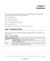
... ports, view the front panel LEDs, and access the power connector. 4-1 v1.0, March 2010 Switch installation involves the following table. Provide a flat table or shelf surface. • Wall-mount installations - Wall-mount: select a location. Table 4-1. You also need the mounting screws supplied with your NETGEAR GS110TP Smart PoE Switch. Chapter 4 Installation This chapter describes the installation procedures...
... ports, view the front panel LEDs, and access the power connector. 4-1 v1.0, March 2010 Switch installation involves the following table. Provide a flat table or shelf surface. • Wall-mount installations - Wall-mount: select a location. Table 4-1. You also need the mounting screws supplied with your NETGEAR GS110TP Smart PoE Switch. Chapter 4 Installation This chapter describes the installation procedures...

GS110TP Hardware Installation Guide
Page 20
... 100 m (328 ft.). Connect the AC power adapter cable into a power source such as the performance of the supplied IEC AC power adapter cable to the switch. When applying power, the Power LED on the Smart Switch Resource CD. 4-4 Installation v1.0, March 2010 If the Power LED does not go on, check that the power cable is plugged in correctly and...
... 100 m (328 ft.). Connect the AC power adapter cable into a power source such as the performance of the supplied IEC AC power adapter cable to the switch. When applying power, the Power LED on the Smart Switch Resource CD. 4-4 Installation v1.0, March 2010 If the Power LED does not go on, check that the power cable is plugged in correctly and...

GS110TP Hardware Installation Guide
Page 28
GS110TP Hardware Installation Guide Interface Eight RJ-45 connectors for 10BASE-T, 100BASE-TX, and 1000BASE-T (Auto Uplink™ on all ports) Two SFP slots for SFP ...-forward Bandwidth: 20 Gbps Address database size: 4K media access control (MAC) addresses per system Mean Time Between Failure (MTBF): 157,004 hours Power Supply 48V/1.25A 60W external power adapter Physical Specifications Dimensions (H x W x D): 236 x 101.6 x 27 mm (9.3 x 4 x 1.07 in) Weight: 0.7/1.55 (kg/lbs) Environmental Specifications Operating temperature: 0°C to 50°C (32...
GS110TP Hardware Installation Guide Interface Eight RJ-45 connectors for 10BASE-T, 100BASE-TX, and 1000BASE-T (Auto Uplink™ on all ports) Two SFP slots for SFP ...-forward Bandwidth: 20 Gbps Address database size: 4K media access control (MAC) addresses per system Mean Time Between Failure (MTBF): 157,004 hours Power Supply 48V/1.25A 60W external power adapter Physical Specifications Dimensions (H x W x D): 236 x 101.6 x 27 mm (9.3 x 4 x 1.07 in) Weight: 0.7/1.55 (kg/lbs) Environmental Specifications Operating temperature: 0°C to 50°C (32...


