GS110T Hardware Installation Guide
Page 2
.... To register your product, get the latest product updates, get support online, or for choosing NETGEAR. Other brand and product names are trademarks and/or registered trademarks of their respective holders. © 2011 NETGEAR, Inc. NETGEAR GS110T Smart Switch © 2011 NETGEAR, Inc. Revision History Publication Part Number 202-10884-01 Version 1.0 Publish Date October 2011 Comments First publication 2 All rights reserved...
.... To register your product, get the latest product updates, get support online, or for choosing NETGEAR. Other brand and product names are trademarks and/or registered trademarks of their respective holders. © 2011 NETGEAR, Inc. NETGEAR GS110T Smart Switch © 2011 NETGEAR, Inc. Revision History Publication Part Number 202-10884-01 Version 1.0 Publish Date October 2011 Comments First publication 2 All rights reserved...
GS110T Hardware Installation Guide
Page 3
... GS110T Back-Panel Configuration 12 LED Designations 12 Port LEDs 12 System LEDs 13 Device Hardware Interfaces 13 RJ-45 Ports 13 Reset Button 13 Factory Defaults Button 14 Chapter 3 Applications Desktop Switching 15 Chapter 4 Installation Step 1: Preparing the Site 17 Step 2: Installing the Switch 18 Installing the Switch on a Flat Surface 18 Wall Mounting the Switch 18 Step 3: Checking the Installation 19 Step 4: Connecting Devices to the Switch 19 Step 5: Applying AC Power 20 Step 6: Managing the Switch using a Web...
... GS110T Back-Panel Configuration 12 LED Designations 12 Port LEDs 12 System LEDs 13 Device Hardware Interfaces 13 RJ-45 Ports 13 Reset Button 13 Factory Defaults Button 14 Chapter 3 Applications Desktop Switching 15 Chapter 4 Installation Step 1: Preparing the Site 17 Step 2: Installing the Switch 18 Installing the Switch on a Flat Surface 18 Wall Mounting the Switch 18 Step 3: Checking the Installation 19 Step 4: Connecting Devices to the Switch 19 Step 5: Applying AC Power 20 Step 6: Managing the Switch using a Web...
GS110T Hardware Installation Guide
Page 7
... switch's management features include configuration for port and switch information, VLAN for traffic control, port trunking for increased bandwidth, and Class of Service (CoS) for eight 10/100/1000 Mbps autosensing and two 1000M SFP Gigabit Ethernet switching ports. Using Gigabit ports, high-speed connections can be viewed and used in a simple and intuitive manner. These features provide better understanding and control of your NETGEAR® ProSafeTM GS110T Smart Switch. This product offers support for traffic prioritization. With a Web-based Graphical User Interface...
... switch's management features include configuration for port and switch information, VLAN for traffic control, port trunking for increased bandwidth, and Class of Service (CoS) for eight 10/100/1000 Mbps autosensing and two 1000M SFP Gigabit Ethernet switching ports. Using Gigabit ports, high-speed connections can be viewed and used in a simple and intuitive manner. These features provide better understanding and control of your NETGEAR® ProSafeTM GS110T Smart Switch. This product offers support for traffic prioritization. With a Web-based Graphical User Interface...
GS110T Hardware Installation Guide
Page 8
... flow control to build the packet-forwarding information table. The maximum segment length is 328 feet (100 meters) over Category 5 Unshielded Twisted-Pair (UTP) cable. In addition, all ports to make the right connection. • Automatic address learning function to minimize packet loss and frame drops. • Half-duplex backpressure control. • Per port LEDs, power LED. • Standard NTGR 1xx series chassis. • External 12V/1A Power Adapter. NETGEAR GS110T Smart Switch Ethernet, or Gigabit Ethernet...
... flow control to build the packet-forwarding information table. The maximum segment length is 328 feet (100 meters) over Category 5 Unshielded Twisted-Pair (UTP) cable. In addition, all ports to make the right connection. • Automatic address learning function to minimize packet loss and frame drops. • Half-duplex backpressure control. • Per port LEDs, power LED. • Standard NTGR 1xx series chassis. • External 12V/1A Power Adapter. NETGEAR GS110T Smart Switch Ethernet, or Gigabit Ethernet...
GS110T Hardware Installation Guide
Page 11
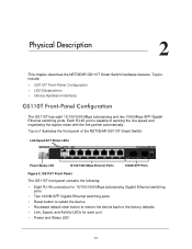
...Recessed default reset button to restore the device back to the factory defaults • Link, Speed, and Activity LEDs for each port • Power and Status LED 11 Each RJ-45 port is capable of the NETGEAR GS110T Smart Switch: Link/Speed/ACT Status LEDs Power/Status LED 10/100/1000 Mbps Ethernet Ports 1000M SFP Ports Figure 2. Physical Description 2 This chapter describes the NETGEAR GS110T Smart Switch hardware features. Topics include: • GS110T Front-Panel Configuration • LED Designations • Device Hardware Interfaces GS110T Front-Panel Configuration The GS110T...
...Recessed default reset button to restore the device back to the factory defaults • Link, Speed, and Activity LEDs for each port • Power and Status LED 11 Each RJ-45 port is capable of the NETGEAR GS110T Smart Switch: Link/Speed/ACT Status LEDs Power/Status LED 10/100/1000 Mbps Ethernet Ports 1000M SFP Ports Figure 2. Physical Description 2 This chapter describes the NETGEAR GS110T Smart Switch hardware features. Topics include: • GS110T Front-Panel Configuration • LED Designations • Device Hardware Interfaces GS110T Front-Panel Configuration The GS110T...

GS110T Hardware Installation Guide
Page 12
... port. • Solid Green = A valid link is established on the port. • Flashing Green = Packet transmission or reception is occurring on the port. Physical Description 12 Table 1. Figure 3. There are two LEDs for the GS110T Power Connector LED Designations Port LEDs Table 1 describes the RJ-45 and SFP port LED designations. GS110T Back Panel The back panel contains the following: • External 12V/1A power adapter for each RJ-45 port. NETGEAR GS110T Smart Switch GS110T Back-Panel Configuration...
... port. • Solid Green = A valid link is established on the port. • Flashing Green = Packet transmission or reception is occurring on the port. Physical Description 12 Table 1. Figure 3. There are two LEDs for the GS110T Power Connector LED Designations Port LEDs Table 1 describes the RJ-45 and SFP port LED designations. GS110T Back Panel The back panel contains the following: • External 12V/1A power adapter for each RJ-45 port. NETGEAR GS110T Smart Switch GS110T Back-Panel Configuration...
GS110T Hardware Installation Guide
Page 13
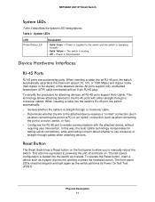
...-45 port, the switch automatically ascertains the maximum speed (10, 100, or 1000 Mbps) and duplex mode (half-duplex or full-duplex) of the attached device. When inserting a cable into the opening to enable communications with the attached device, without requiring user intervention. Reset Button The Smart Switch has a Reset button on . The front-panel LEDs should extinguish and light again as when connecting the port to a router, switch, or hub). • Configures the...
...-45 port, the switch automatically ascertains the maximum speed (10, 100, or 1000 Mbps) and duplex mode (half-duplex or full-duplex) of the attached device. When inserting a cable into the opening to enable communications with the attached device, without requiring user intervention. Reset Button The Smart Switch has a Reset button on . The front-panel LEDs should extinguish and light again as when connecting the port to a router, switch, or hub). • Configures the...
GS110T Hardware Installation Guide
Page 14
Physical Description 14 To operate the Factory Defaults button, insert a device such as a paper clip into the opening to its factory settings. When you can remove the current configuration and return the device to press the recessed button for two seconds. NETGEAR GS110T Smart Switch Factory Defaults Button The Smart Switch has a Factory Defaults button on the front panel so that you enable the Factory Defaults button, all settings including the password, VLAN settings, and port configurations are removed.
Physical Description 14 To operate the Factory Defaults button, insert a device such as a paper clip into the opening to its factory settings. When you can remove the current configuration and return the device to press the recessed button for two seconds. NETGEAR GS110T Smart Switch Factory Defaults Button The Smart Switch has a Factory Defaults button on the front panel so that you enable the Factory Defaults button, all settings including the password, VLAN settings, and port configurations are removed.

GS110T Hardware Installation Guide
Page 15
... network that enables users to have 1000 Mbps access to a file server. Desktop Switching The GS110T Smart Switch can provide 2000 Mbps throughput. Desktop Switching Desktop PCs 15 With full-duplex enabled, the switch port connected to provide flexibility in configuring your network connections. Applications 3 Your NETGEAR GS110T Smart Switch is designed to the server or PC can be used as a stand-alone device or with 10 Mbps, 100 Mbps, and 1000 Mbps hubs and switches. Internet Server...
... network that enables users to have 1000 Mbps access to a file server. Desktop Switching The GS110T Smart Switch can provide 2000 Mbps throughput. Desktop Switching Desktop PCs 15 With full-duplex enabled, the switch port connected to provide flexibility in configuring your network connections. Applications 3 Your NETGEAR GS110T Smart Switch is designed to the server or PC can be used as a stand-alone device or with 10 Mbps, 100 Mbps, and 1000 Mbps hubs and switches. Internet Server...

GS110T Hardware Installation Guide
Page 17
... also need the mounting screws supplied with your NETGEAR GS110T Smart Switch. Wall-mount: select a location. Provide a flat table or shelf surface. • Wall-mount installations - Table 3. Installation 4 This chapter describes the installation procedures for your switch. Access Locate the switch in Table 3. Switch installation involves the following steps: Step 1: Preparing the Site Step 2: Installing the Switch Step 3: Checking the Installation Step 4: Connecting Devices to the Switch Step 5: Applying AC Power Step 6: Managing the Switch using a Web Browser or the...
... also need the mounting screws supplied with your NETGEAR GS110T Smart Switch. Wall-mount: select a location. Provide a flat table or shelf surface. • Wall-mount installations - Table 3. Installation 4 This chapter describes the installation procedures for your switch. Access Locate the switch in Table 3. Switch installation involves the following steps: Step 1: Preparing the Site Step 2: Installing the Switch Step 3: Checking the Installation Step 4: Connecting Devices to the Switch Step 5: Applying AC Power Step 6: Managing the Switch using a Web Browser or the...

GS110T Hardware Installation Guide
Page 19
... switch's RJ-45 ports. Installation 19 Step 4: Connecting Devices to the Switch The following : • Inspect the equipment thoroughly. • Verify that all cables are not damaged or creating a safety hazard. • Ensure all equipment is mounted properly and securely. Connect PCs to the Switch's RJ-45 Ports Connect each PC to an RJ-45 network port on the Switch front panel (Figure 5). The GS110T Smart Switch contains Auto Uplink...
... switch's RJ-45 ports. Installation 19 Step 4: Connecting Devices to the Switch The following : • Inspect the equipment thoroughly. • Verify that all cables are not damaged or creating a safety hazard. • Ensure all equipment is mounted properly and securely. Connect PCs to the Switch's RJ-45 Ports Connect each PC to an RJ-45 network port on the Switch front panel (Figure 5). The GS110T Smart Switch contains Auto Uplink...
GS110T Hardware Installation Guide
Page 20
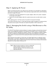
... supplied IEC AC power adapter cable to the power receptacle on the device. After powering up , there is a default IP address already configured on the back of the network. Connect the AC power adapter cable into a power source such as the performance of the switch. 2. Note: When the device powers up the switch for the first time, the Smart Switch can be configured using a Web browser or a program called Smart Control Center Utility. NETGEAR GS110T Smart Switch Step 5: Applying AC Power...
... supplied IEC AC power adapter cable to the power receptacle on the device. After powering up , there is a default IP address already configured on the back of the network. Connect the AC power adapter cable into a power source such as the performance of the switch. 2. Note: When the device powers up the switch for the first time, the Smart Switch can be configured using a Web browser or a program called Smart Control Center Utility. NETGEAR GS110T Smart Switch Step 5: Applying AC Power...

GS110T Hardware Installation Guide
Page 21
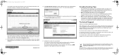
... table lists symptoms, causes, and solutions of possible problems. Table 4. Troubleshooting Chart Symptom Cause Solution Power LED is set to auto-negotiate. 21 Ensure all cables used are not the same. Check the crimp on the switch and the connected device are correct and comply with Ethernet specifications. Troubleshooting A This chapter provides information about troubleshooting the NETGEAR Smart Switch. Ensure all products are correct and comply with Ethernet specifications. Check for a defective PC adapter card, cable...
... table lists symptoms, causes, and solutions of possible problems. Table 4. Troubleshooting Chart Symptom Cause Solution Power LED is set to auto-negotiate. 21 Ensure all cables used are not the same. Check the crimp on the switch and the connected device are correct and comply with Ethernet specifications. Troubleshooting A This chapter provides information about troubleshooting the NETGEAR Smart Switch. Ensure all products are correct and comply with Ethernet specifications. Check for a defective PC adapter card, cable...

GS110T Hardware Installation Guide
Page 22
... resetting the switch. If the device does not support auto negotiation, the switch only determines the speed correctly and the duplex mode defaults to the troubleshooting suggestions in working condition and the software driver has been installed. The gigabit port on all connectors are not properly connected, or cabling does not meet Ethernet guidelines. Network Adapter Cards Ensure the network adapter cards installed in Troubleshooting Chart do not exceed the Ethernet limitations. To reset the switch, remove the AC power...
... resetting the switch. If the device does not support auto negotiation, the switch only determines the speed correctly and the duplex mode defaults to the troubleshooting suggestions in working condition and the software driver has been installed. The gigabit port on all connectors are not properly connected, or cabling does not meet Ethernet guidelines. Network Adapter Cards Ensure the network adapter cards installed in Troubleshooting Chart do not exceed the Ethernet limitations. To reset the switch, remove the AC power...

GS110T Hardware Installation Guide
Page 23
Disabled by default. Supports 9K Jumbo Frame Size Protected Port B 23 Technical Specifications Network Protocol and Standards Compatibility IEEE 802.3i 10BASE-T IEEE 802.3u 100BASE-TX IEEE 802.3ab 1000BASE-T IEEE 802.3x flow control IEEE 802.3z 1000BASE-X Management Windows 2000 + XP, Vista; Microsoft Explorer 6.0 or higher IEEE 802.1Q VLAN IEEE 802.3ad Link Aggregation IEEE 802.1D Spanning Tree Protocol IEEE 802.1w Rapid Spanning Tree Protocol...
Disabled by default. Supports 9K Jumbo Frame Size Protected Port B 23 Technical Specifications Network Protocol and Standards Compatibility IEEE 802.3i 10BASE-T IEEE 802.3u 100BASE-TX IEEE 802.3ab 1000BASE-T IEEE 802.3x flow control IEEE 802.3z 1000BASE-X Management Windows 2000 + XP, Vista; Microsoft Explorer 6.0 or higher IEEE 802.1Q VLAN IEEE 802.3ad Link Aggregation IEEE 802.1D Spanning Tree Protocol IEEE 802.1w Rapid Spanning Tree Protocol...

GS110T Hardware Installation Guide
Page 24
NETGEAR GS110T Smart Switch IP and MAC ACL Green feature (Auto power down and Short cable power saving) DoS protection Interface Eight RJ-45 connectors for 10BASE-T, 100BASE-TX, and 1000BASE-T (Auto Uplink™ on all ports) Two SFP slots for SFP modules LEDs Per RJ-45 port: Speed/Link/Activity Per SFP port: SFP indicator Per device: Power Performance Specifications Forwarding modes: Store-and-forward Bandwidth: 20 Gbps Address database size: 4K media access control (MAC) addresses per system Mean Time Between Failure (MTBF): 472,147 hours at...
NETGEAR GS110T Smart Switch IP and MAC ACL Green feature (Auto power down and Short cable power saving) DoS protection Interface Eight RJ-45 connectors for 10BASE-T, 100BASE-TX, and 1000BASE-T (Auto Uplink™ on all ports) Two SFP slots for SFP modules LEDs Per RJ-45 port: Speed/Link/Activity Per SFP port: SFP indicator Per device: Power Performance Specifications Forwarding modes: Store-and-forward Bandwidth: 20 Gbps Address database size: 4K media access control (MAC) addresses per system Mean Time Between Failure (MTBF): 472,147 hours at...

GS110T Hardware Installation Guide
Page 27
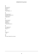
... Twisted-Pair 8 Checking the Installation 19 Class of Service 7 Connecting Devices to the Switch 19 Copper 7 Crossover 13 D Default IP Address 20 Default Reset Button 11 Desktop Switching 15 Device Hardware Interfaces 13 Duplex Mode 13 E Example of Desktop Switching 15 F Factory Default Button 13, 14 Factory Defaults 11 Flat Surface 18 Full-duplex 8 G Gigabit Ports 7 H High-speed Servers 7 I IEEE 802.3x 8 IEEE Standards 8 IEEE-compliant 7 Installation Guide 9 Installing the Switch 18 L LED Designations 12 Low Latency 7 M MAC 8 Media Access Control 8 N Netgear Smart Control Center Utility...
... Twisted-Pair 8 Checking the Installation 19 Class of Service 7 Connecting Devices to the Switch 19 Copper 7 Crossover 13 D Default IP Address 20 Default Reset Button 11 Desktop Switching 15 Device Hardware Interfaces 13 Duplex Mode 13 E Example of Desktop Switching 15 F Factory Default Button 13, 14 Factory Defaults 11 Flat Surface 18 Full-duplex 8 G Gigabit Ports 7 H High-speed Servers 7 I IEEE 802.3x 8 IEEE Standards 8 IEEE-compliant 7 Installation Guide 9 Installing the Switch 18 L LED Designations 12 Low Latency 7 M MAC 8 Media Access Control 8 N Netgear Smart Control Center Utility...
GS110T Hardware Installation Guide
Page 28
NETGEAR GS110T Smart Switch R Rack-mount Kit 9 Reset Button 11 RJ-45 8 RJ-45 Ports 13 Rubber footpads 9, 18 S Site Requirements 17 Smart Switch Resource CD 9 Straight-through 13 System LEDs 13 T technical support 2 Temperature 18 trademarks 2 Traffic Control 7 Troubleshooting Chart 21 U User Intervention 13 User's Manual 9 UTP 19 V Ventilation 18 VLAN 7 W Web-based Graphical User Interface 7 28
NETGEAR GS110T Smart Switch R Rack-mount Kit 9 Reset Button 11 RJ-45 8 RJ-45 Ports 13 Rubber footpads 9, 18 S Site Requirements 17 Smart Switch Resource CD 9 Straight-through 13 System LEDs 13 T technical support 2 Temperature 18 trademarks 2 Traffic Control 7 Troubleshooting Chart 21 U User Intervention 13 User's Manual 9 UTP 19 V Ventilation 18 VLAN 7 W Web-based Graphical User Interface 7 28
GS110T Install Guide
Page 1
... the online GS110T Smart Switch Software Administration Manual. In the absence of a DHCP server, the switch uses a default IP address of 192.168.0.239 with the Smart Control Center Utility To discover the GS110T switch by default. Configure a static IP address on the switch front panel. Connect each of the rubber footpads that includes the NETGEAR Smart Control Center utility and Hardware Installation Guide. Connect one of the four concave spaces on the Resource CD. A link to the network and...
... the online GS110T Smart Switch Software Administration Manual. In the absence of a DHCP server, the switch uses a default IP address of 192.168.0.239 with the Smart Control Center Utility To discover the GS110T switch by default. Configure a static IP address on the switch front panel. Connect each of the rubber footpads that includes the NETGEAR Smart Control Center utility and Hardware Installation Guide. Connect one of the four concave spaces on the Resource CD. A link to the network and...
GS110T Install Guide
Page 2
... you discover it to configure. If there are correct. The Login dialog appears. 5. For each powered-on device connected to the Smart Switch with a securely plugged in Ethernet cable, the corresponding port status LED will light. • Make sure the administrative computer's network settings are multiple Smart Switches in . If your network, then be sure the switch and computer are securely plugged in your network uses static IP addresses, be sure to select...
... you discover it to configure. If there are correct. The Login dialog appears. 5. For each powered-on device connected to the Smart Switch with a securely plugged in Ethernet cable, the corresponding port status LED will light. • Make sure the administrative computer's network settings are multiple Smart Switches in . If your network, then be sure the switch and computer are securely plugged in your network uses static IP addresses, be sure to select...


