FSM726v3 Hardware Installation Guide
Page 1
Plumeria Drive San Jose, CA 95134 USA 202-10452-03 July 2009 Managed Layer 2 Switch with 2 Gigabit Ethernet Ports FSM726 Hardware Installation Guide NETGEAR, Inc. 350 E.
Plumeria Drive San Jose, CA 95134 USA 202-10452-03 July 2009 Managed Layer 2 Switch with 2 Gigabit Ethernet Ports FSM726 Hardware Installation Guide NETGEAR, Inc. 350 E.
FSM726v3 Hardware Installation Guide
Page 2
...out in this document without notice. Certificate of the Manufacturer/Importer It is hereby certified that the NETGEAR ProSafe 24-Port Ethernet L2 Managed Switch Model FSM726 has been suppressed in accordance with part 15 of some equipment (for Interference (VCCI)...the following two conditions: • This device may occur, in the operating instructions. E-mail: support@netgear.com North American NETGEAR website: http://www.netgear.com Trademarks NETGEAR, the NETGEAR logo, ProSafe, and Auto Uplink are registered trademarks or trademarks of product and software upgrades. Microsoft,...
...out in this document without notice. Certificate of the Manufacturer/Importer It is hereby certified that the NETGEAR ProSafe 24-Port Ethernet L2 Managed Switch Model FSM726 has been suppressed in accordance with part 15 of some equipment (for Interference (VCCI)...the following two conditions: • This device may occur, in the operating instructions. E-mail: support@netgear.com North American NETGEAR website: http://www.netgear.com Trademarks NETGEAR, the NETGEAR logo, ProSafe, and Auto Uplink are registered trademarks or trademarks of product and software upgrades. Microsoft,...
FSM726v3 Hardware Installation Guide
Page 3
... digital apparatus as set out in a particular installation. Canadian Department of Communications Radio Interference Regulations This digital apparatus (NETGEAR ProSafe 24-Port Ethernet L2 Managed Switch Model FSM726) does not exceed the Class A limits for radio-noise emissions from that which case the user may...232;glement sur le brouillage radioélectrique du ministère des Communications Cet appareil numérique (NETGEAR ProSafe 24-Port Ethernet L2 Managed Switch Model FSM726) respecte les limites de bruits radioélectriques visant les appareils numériques de classe A ...
... digital apparatus as set out in a particular installation. Canadian Department of Communications Radio Interference Regulations This digital apparatus (NETGEAR ProSafe 24-Port Ethernet L2 Managed Switch Model FSM726) does not exceed the Class A limits for radio-noise emissions from that which case the user may...232;glement sur le brouillage radioélectrique du ministère des Communications Cet appareil numérique (NETGEAR ProSafe 24-Port Ethernet L2 Managed Switch Model FSM726) respecte les limites de bruits radioélectriques visant les appareils numériques de classe A ...

FSM726v3 Hardware Installation Guide
Page 4
World Wide Web NETGEAR maintains a World Wide Web home page that you can access at the universal resource locator (URL) http://www.netgear.com. A direct connection to the Internet and a Web browser such as Internet Explorer or Netscape are required. Product and Publication Details Model Number: Publication Date: Product Family: Product Name: Home or Business Product: Language: Publication Part Number: Publication Version Number FSM726 July 2009 switch chassis Managed Layer 2 Switch Business English 202-10452-03 1.0 iv v1.0, July 2009
World Wide Web NETGEAR maintains a World Wide Web home page that you can access at the universal resource locator (URL) http://www.netgear.com. A direct connection to the Internet and a Web browser such as Internet Explorer or Netscape are required. Product and Publication Details Model Number: Publication Date: Product Family: Product Name: Home or Business Product: Language: Publication Part Number: Publication Version Number FSM726 July 2009 switch chassis Managed Layer 2 Switch Business English 202-10452-03 1.0 iv v1.0, July 2009
FSM726v3 Hardware Installation Guide
Page 5
...with 2 Gigabit Ethernet Ports FSM726 Hardware Installation Guide describes how to highlight information of importance or special interest. About This Manual The NETGEAR® ProSafe® Managed Layer 2 Switch with intermediate computer and Internet skills. Conventions, Formats, and Scope The conventions, formats, and scope of note might result in ...type of this manual are described in this manual is used to install, configure and troubleshoot the ProSafe 24Port Ethernet L2 Managed Switch Model FSM726. The information in the following paragraphs: • Typographical Conventions.
...with 2 Gigabit Ethernet Ports FSM726 Hardware Installation Guide describes how to highlight information of importance or special interest. About This Manual The NETGEAR® ProSafe® Managed Layer 2 Switch with intermediate computer and Internet skills. Conventions, Formats, and Scope The conventions, formats, and scope of note might result in ...type of this manual are described in this manual is used to install, configure and troubleshoot the ProSafe 24Port Ethernet L2 Managed Switch Model FSM726. The information in the following paragraphs: • Typographical Conventions.
FSM726v3 Hardware Installation Guide
Page 6
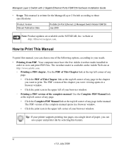
...on the Adobe Web site at http://kbserver.netgear.com. vi v1.0, July 2009 Your computer must have the free Adobe Acrobat reader installed in the upper left corner of your browser window. The PDF version of any page in the manual. Managed Layer 2 Switch with 2 Gigabit Ethernet Ports FSM726 Hardware ... ink by selecting this manual, you want to Print This Manual To print this feature. Tip: If your printer supports printing two pages on the NETGEAR, Inc. Use the Complete PDF Manual link at the top left corner of any page. • Click the Complete PDF Manual link at the...
...on the Adobe Web site at http://kbserver.netgear.com. vi v1.0, July 2009 Your computer must have the free Adobe Acrobat reader installed in the upper left corner of your browser window. The PDF version of any page in the manual. Managed Layer 2 Switch with 2 Gigabit Ethernet Ports FSM726 Hardware ... ink by selecting this manual, you want to Print This Manual To print this feature. Tip: If your printer supports printing two pages on the NETGEAR, Inc. Use the Complete PDF Manual link at the top left corner of any page. • Click the Complete PDF Manual link at the...

FSM726v3 Hardware Installation Guide
Page 7
Managed Layer 2 Switch with 2 Gigabit Ethernet Ports FSM726 Hardware Installation Guide Revision History Part Number Version Number Date Description 202-10452-01 1.0 202-10452-02 1.0 202-10452-03 1.0 October 2008 November 2008 July 2009 Original publication. Changed model name vii v1.0, July 2009
Managed Layer 2 Switch with 2 Gigabit Ethernet Ports FSM726 Hardware Installation Guide Revision History Part Number Version Number Date Description 202-10452-01 1.0 202-10452-02 1.0 202-10452-03 1.0 October 2008 November 2008 July 2009 Original publication. Changed model name vii v1.0, July 2009

FSM726v3 Hardware Installation Guide
Page 8
Managed Layer 2 Switch with 2 Gigabit Ethernet Ports FSM726 Hardware Installation Guide viii v1.0, July 2009
Managed Layer 2 Switch with 2 Gigabit Ethernet Ports FSM726 Hardware Installation Guide viii v1.0, July 2009

FSM726v3 Hardware Installation Guide
Page 9
... Front Panel and LEDs ...1-1 Rear Panel ...1-3 Safety Instructions ...1-3 Chapter 2 Hardware Installation Package Contents ...2-1 Protecting Against Electrostatic Discharge 2-2 Unpacking the Hardware 2-2 Installation ...2-3 Selecting a Location 2-3 Installing the Switch 2-4 Checking the Installation 2-5 Connecting to Power and Checking the LEDs 2-5 SFP Modules ...2-6 Connecting Equipment to the...
... Front Panel and LEDs ...1-1 Rear Panel ...1-3 Safety Instructions ...1-3 Chapter 2 Hardware Installation Package Contents ...2-1 Protecting Against Electrostatic Discharge 2-2 Unpacking the Hardware 2-2 Installation ...2-3 Selecting a Location 2-3 Installing the Switch 2-4 Checking the Installation 2-5 Connecting to Power and Checking the LEDs 2-5 SFP Modules ...2-6 Connecting Equipment to the...

FSM726v3 Hardware Installation Guide
Page 10
Managed Layer 2 Switch with 2 Gigabit Ethernet Ports FSM726 Hardware Installation Guide Appendix A Factory Default Settings and Technical Specifications Factory Default Settings A-1 Technical Specifications A-2 x v1.0, July 2009
Managed Layer 2 Switch with 2 Gigabit Ethernet Ports FSM726 Hardware Installation Guide Appendix A Factory Default Settings and Technical Specifications Factory Default Settings A-1 Technical Specifications A-2 x v1.0, July 2009
FSM726v3 Hardware Installation Guide
Page 11
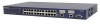
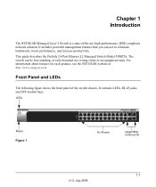
..., IEEE-compliant network solution. The switch can use to eliminate bottlenecks, boost performance, and increase productivity. Chapter 1 Introduction The NETGEAR Managed Layer 2 Switch is a state-of the switch chassis. This guide describes the ProSafe 24-Port Ethernet L2 Managed Switch Model FSM726. LEDs Reset Figure 1... RJ-45 jacks copper/fiber combo ports 1-1 v1.0, July 2009 For information about features for each product, see the NETGEAR website at http://www.netgear.com. It contains LEDs, RJ-45...
..., IEEE-compliant network solution. The switch can use to eliminate bottlenecks, boost performance, and increase productivity. Chapter 1 Introduction The NETGEAR Managed Layer 2 Switch is a state-of the switch chassis. This guide describes the ProSafe 24-Port Ethernet L2 Managed Switch Model FSM726. LEDs Reset Figure 1... RJ-45 jacks copper/fiber combo ports 1-1 v1.0, July 2009 For information about features for each product, see the NETGEAR website at http://www.netgear.com. It contains LEDs, RJ-45...

FSM726v3 Hardware Installation Guide
Page 12
...10/100 Mbps. • If port 25-26 media is established on self-test (POST) in progress. • Solid yellow. Managed Layer 2 Switch with 2 Gigabit Ethernet Ports FSM726 Hardware Installation Guide The following table describes the LEDs on the port. • Blinking green. A valid 100Mbps SFP...Off status. 1-2 Introduction v1.0, July 2009 A valid 1000 Mbps link is established on the port. • Solid green. Power is supplied and the switch is booting up. • Blinking yellow. A valid 10/00Mbps link is established on the port. • Blinking Yellow. POST, CPU, or ...
...10/100 Mbps. • If port 25-26 media is established on self-test (POST) in progress. • Solid yellow. Managed Layer 2 Switch with 2 Gigabit Ethernet Ports FSM726 Hardware Installation Guide The following table describes the LEDs on the port. • Blinking green. A valid 100Mbps SFP...Off status. 1-2 Introduction v1.0, July 2009 A valid 1000 Mbps link is established on the port. • Solid green. Power is supplied and the switch is booting up. • Blinking yellow. A valid 10/00Mbps link is established on the port. • Blinking Yellow. POST, CPU, or ...
FSM726v3 Hardware Installation Guide
Page 13
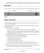
... damaged. - An object has fallen into the product. - The product does not operate correctly when you to help protect your trained service provider. Managed Layer 2 Switch with a lightning bolt could expose you follow service markings. - Opening or removing covers that are marked with the triangular symbol with 2 Gigabit Ethernet Ports FSM726...
... damaged. - An object has fallen into the product. - The product does not operate correctly when you to help protect your trained service provider. Managed Layer 2 Switch with a lightning bolt could expose you follow service markings. - Opening or removing covers that are marked with the triangular symbol with 2 Gigabit Ethernet Ports FSM726...

FSM726v3 Hardware Installation Guide
Page 14
... percent of external power source indicated on the power supply is approved for any cables. 1-4 Introduction v1.0, July 2009 Be sure that the voltage selection switch (if provided) on the electrical ratings label. Do not use in most of power source required, consult your service provider or local power company. •... Japan and 100 V, 60 Hz in western Japan - 230 V, 50 Hz in your system, be sure that nothing rests on or tripped over. Managed Layer 2 Switch with properly grounded plugs. • Observe extension cable and power strip ratings.
... percent of external power source indicated on the power supply is approved for any cables. 1-4 Introduction v1.0, July 2009 Be sure that the voltage selection switch (if provided) on the electrical ratings label. Do not use in most of power source required, consult your service provider or local power company. •... Japan and 100 V, 60 Hz in western Japan - 230 V, 50 Hz in your system, be sure that nothing rests on or tripped over. Managed Layer 2 Switch with properly grounded plugs. • Observe extension cable and power strip ratings.

FSM726v3 Hardware Installation Guide
Page 15
Consult a licensed electrician or your power company for site modifications. • Always follow your local and national wiring rules. • Move products with 2 Gigabit Ethernet Ports FSM726 Hardware Installation Guide • Do not modify power cables or plugs. ensure that all casters and stabilizers are firmly connected to the system. Avoid sudden stops and uneven surfaces. Managed Layer 2 Switch with care; Introduction 1-5 v1.0, July 2009
Consult a licensed electrician or your power company for site modifications. • Always follow your local and national wiring rules. • Move products with 2 Gigabit Ethernet Ports FSM726 Hardware Installation Guide • Do not modify power cables or plugs. ensure that all casters and stabilizers are firmly connected to the system. Avoid sudden stops and uneven surfaces. Managed Layer 2 Switch with care; Introduction 1-5 v1.0, July 2009

FSM726v3 Hardware Installation Guide
Page 16
Managed Layer 2 Switch with 2 Gigabit Ethernet Ports FSM726 Hardware Installation Guide 1-6 Introduction v1.0, July 2009
Managed Layer 2 Switch with 2 Gigabit Ethernet Ports FSM726 Hardware Installation Guide 1-6 Introduction v1.0, July 2009
FSM726v3 Hardware Installation Guide
Page 17
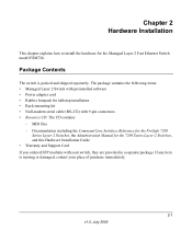
... preinstalled software • Power adapter cord • Rubber footpads for the Managed Layer 2 Fast Ethernet Switch model FSM726. MIB files - Chapter 2 Hardware Installation This chapter explains how to install the hardware for tabletop installation • Rack-mounting...; Resource CD: The CD contains - Documentation including the Command Line Interface Reference for the ProSafe 7200 Series Layer-2 Switches, the Administration Manual for the 7200 Series Layer-2 Switches, and this Hardware Installation Guide • Warranty and Support Card If you ordered SFP modules with your place of ...
... preinstalled software • Power adapter cord • Rubber footpads for the Managed Layer 2 Fast Ethernet Switch model FSM726. MIB files - Chapter 2 Hardware Installation This chapter explains how to install the hardware for tabletop installation • Rack-mounting...; Resource CD: The CD contains - Documentation including the Command Line Interface Reference for the ProSafe 7200 Series Layer-2 Switches, the Administration Manual for the 7200 Series Layer-2 Switches, and this Hardware Installation Guide • Warranty and Support Card If you ordered SFP modules with your place of ...

FSM726v3 Hardware Installation Guide
Page 18
See "Package Contents" on page 2-3. 3. When unpacking a static-sensitive component from your local NETGEAR reseller for damage. If possible, use antistatic floor pads, workbench pads, and an antistatic grounding strap. Unpacking the Hardware Check...items are ready to prevent damage from the boxes. Report any item is found missing or damaged, contact your body. 2. Managed Layer 2 Switch with 2 Gigabit Ethernet Ports FSM726 Hardware Installation Guide Protecting Against Electrostatic Discharge Warning: Static electricity can harm delicate components inside your body before ...
See "Package Contents" on page 2-3. 3. When unpacking a static-sensitive component from your local NETGEAR reseller for damage. If possible, use antistatic floor pads, workbench pads, and an antistatic grounding strap. Unpacking the Hardware Check...items are ready to prevent damage from the boxes. Report any item is found missing or damaged, contact your body. 2. Managed Layer 2 Switch with 2 Gigabit Ethernet Ports FSM726 Hardware Installation Guide Protecting Against Electrostatic Discharge Warning: Static electricity can harm delicate components inside your body before ...

FSM726v3 Hardware Installation Guide
Page 19
...the rack mounting kit supplied with a maximum relative humidity of 90%, noncondensing. Provide a power source within 6 feet (1.8 meters) of the switch. Install the switch in a standard 19-inch (48.26-centimeter) rack, wall mounted, or left freestanding (placed on the sides of the installation location.... Keep at least 2 inches (5.08 centimeters) free on page 2-5 4. Check the installation. Do not restrict airflow by a wall switch, which can be mounted in a site free from heat sources such as motors), vibration, dust, and direct exposure to 50°C). Select...
...the rack mounting kit supplied with a maximum relative humidity of 90%, noncondensing. Provide a power source within 6 feet (1.8 meters) of the switch. Install the switch in a standard 19-inch (48.26-centimeter) rack, wall mounted, or left freestanding (placed on the sides of the installation location.... Keep at least 2 inches (5.08 centimeters) free on page 2-5 4. Check the installation. Do not restrict airflow by a wall switch, which can be mounted in a site free from heat sources such as motors), vibration, dust, and direct exposure to 50°C). Select...

FSM726v3 Hardware Installation Guide
Page 20
... 2-4 v1.0, July 2009 Hardware Installation Use the provided Phillips head screws to fasten the brackets to the sides of the switch. Installing the Switch on a flat surface or in a rack, you need the 19-inch rack-mount kit supplied with 2 Gigabit Ethernet Ports... FSM726 Hardware Installation Guide Table 2-1. The rubber footpads cushion the switch against shock and vibrations. Site Requirements for Switch Location (continued) Requirements Cabling Route the cable to the side of electrical noise such as radio transmitters, broadcast...
... 2-4 v1.0, July 2009 Hardware Installation Use the provided Phillips head screws to fasten the brackets to the sides of the switch. Installing the Switch on a flat surface or in a rack, you need the 19-inch rack-mount kit supplied with 2 Gigabit Ethernet Ports... FSM726 Hardware Installation Guide Table 2-1. The rubber footpads cushion the switch against shock and vibrations. Site Requirements for Switch Location (continued) Requirements Cabling Route the cable to the side of electrical noise such as radio transmitters, broadcast...