FS752TP Hardware Installation Guide
Page 3
Contents Chapter 1 Introduction Overview 6 Features 7 Package Contents 8 Chapter 2 Physical Description FS752TP Front-Panel and Back-Panel Configuration 10 LED Designations 12 System LEDs 12 Port LEDs 13 Device Hardware Interfaces 15 RJ-45 Ports 15 SFP Ports 15 Reset Button 16 Factory Defaults Button 16 Chapter 3 Applications Desktop Switching 18 Chapter 4 Installation Step 1: Preparing...
Contents Chapter 1 Introduction Overview 6 Features 7 Package Contents 8 Chapter 2 Physical Description FS752TP Front-Panel and Back-Panel Configuration 10 LED Designations 12 System LEDs 12 Port LEDs 13 Device Hardware Interfaces 15 RJ-45 Ports 15 SFP Ports 15 Reset Button 16 Factory Defaults Button 16 Chapter 3 Applications Desktop Switching 18 Chapter 4 Installation Step 1: Preparing...
FS752TP Hardware Installation Guide
Page 8
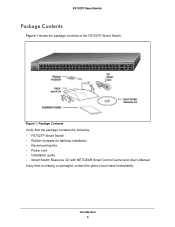
... Green=Link/ACT Select Reset Factory Defaults 1 2 3 4 5 6 7 8 9 10 11 12 13 14 15 16 17 18 19 20 21 22 23 24 25 26 27 28 29 30 31 32 33 34 35 36 37 38 39 40 41 42 43 44 45 46 47 48 49F 50F FS752TP 49T 50T 51 52... • Rackmounting kits • Power cord • Installation guide • Smart Switch Resource CD with NETGEAR Smart Control Center and User's Manual If any item is missing or damaged, contact the place of the FS752TP Smart Switch. FS752TP Smart Switch Package Contents Figure 1 shows the package contents of purchase immediately. Green=1G, Yellow...
... Green=Link/ACT Select Reset Factory Defaults 1 2 3 4 5 6 7 8 9 10 11 12 13 14 15 16 17 18 19 20 21 22 23 24 25 26 27 28 29 30 31 32 33 34 35 36 37 38 39 40 41 42 43 44 45 46 47 48 49F 50F FS752TP 49T 50T 51 52... • Rackmounting kits • Power cord • Installation guide • Smart Switch Resource CD with NETGEAR Smart Control Center and User's Manual If any item is missing or damaged, contact the place of the FS752TP Smart Switch. FS752TP Smart Switch Package Contents Figure 1 shows the package contents of purchase immediately. Green=1G, Yellow...
FS752TP Hardware Installation Guide
Page 10
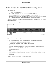
Physical Description 10 Figure 2 illustrates the front panel of the available PoE power remain unused. • LED Mode Figure 3 illustrates the NETGEAR FS752TP back panel. Power/Status LED Factory Defaults Button Reset Button 10/100 Mbps copper ports Combo Ports Figure 2. If the SFP combo ports are in use, copper ports 49 and 50 are...
Physical Description 10 Figure 2 illustrates the front panel of the available PoE power remain unused. • LED Mode Figure 3 illustrates the NETGEAR FS752TP back panel. Power/Status LED Factory Defaults Button Reset Button 10/100 Mbps copper ports Combo Ports Figure 2. If the SFP combo ports are in use, copper ports 49 and 50 are...
FS752TP Hardware Installation Guide
Page 16
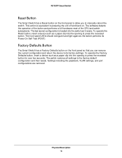
... as a paper clip into the switch as the switch performs its factory settings. Factory Defaults Button The Smart Switch has a Factory Defaults button on . The switch restores all settings to manually reboot the switch. FS752TP Smart Switch Reset Button The Smart Switch has a Reset button on the front panel to allow you can remove the current...
... as a paper clip into the switch as the switch performs its factory settings. Factory Defaults Button The Smart Switch has a Factory Defaults button on . The switch restores all settings to manually reboot the switch. FS752TP Smart Switch Reset Button The Smart Switch has a Reset button on the front panel to allow you can remove the current...
FS752TP Hardware Installation Guide
Page 18
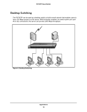
...49-52 Link/Act Mode - Desktop Switching Applications 18 Power Fan PoE Max LED Mode Yellow=PoE Green=Link/ACT Select Reset Factory Defaults 1 2 3 4 5 6 7 8 9 10 11 12 13 14 15 16 17 18 19 20 21...32 33 34 35 36 37 38 39 40 41 42 43 44 45 46 47 48 49F 50F FS752TP 49T 50T 51 52 Ports 1-48, Link/Act Mode - With full-duplex enabled, the switch uplink ...port (port 49 to 52) connected to a file server. FS752TP Smart Switch Desktop Switching The FS752TP can be used as a desktop switch to build a small network that enables users to have ...
...49-52 Link/Act Mode - Desktop Switching Applications 18 Power Fan PoE Max LED Mode Yellow=PoE Green=Link/ACT Select Reset Factory Defaults 1 2 3 4 5 6 7 8 9 10 11 12 13 14 15 16 17 18 19 20 21...32 33 34 35 36 37 38 39 40 41 42 43 44 45 46 47 48 49F 50F FS752TP 49T 50T 51 52 Ports 1-48, Link/Act Mode - With full-duplex enabled, the switch uplink ...port (port 49 to 52) connected to a file server. FS752TP Smart Switch Desktop Switching The FS752TP can be used as a desktop switch to build a small network that enables users to have ...

FS752TP Hardware Installation Guide
Page 23
...Blink=ACT Combo Ports Ports 49-52 Link/Act Mode - Power Fan PoE Max LED Mode Yellow=PoE Green=Link/ACT Select Reset Factory Defaults 1 2 3 4 5 6 7 8 9 10 11 12 13 14 15 16 17 18 19 20 21 ...32 33 34 35 36 37 38 39 40 41 42 43 44 45 46 47 48 49F 50F FS752TP 49T 50T 51 52 Ports 1-48, Link/Act Mode - Note: Ethernet specifications limit the cable length ... make these connections. Connecting Devices to the Switch Connect each PC to the switch's RJ-45 ports. FS752TP Smart Switch Step 4: Connecting Devices to the Switch The following procedure describes how to connect PCs to an...
...Blink=ACT Combo Ports Ports 49-52 Link/Act Mode - Power Fan PoE Max LED Mode Yellow=PoE Green=Link/ACT Select Reset Factory Defaults 1 2 3 4 5 6 7 8 9 10 11 12 13 14 15 16 17 18 19 20 21 ...32 33 34 35 36 37 38 39 40 41 42 43 44 45 46 47 48 49F 50F FS752TP 49T 50T 51 52 Ports 1-48, Link/Act Mode - Note: Ethernet specifications limit the cable length ... make these connections. Connecting Devices to the Switch Connect each PC to the switch's RJ-45 ports. FS752TP Smart Switch Step 4: Connecting Devices to the Switch The following procedure describes how to connect PCs to an...

FS752TP Hardware Installation Guide
Page 24
... Green=Link/ACT Select Reset Factory Defaults 1 2 3 4 5 6 7 8 9 10 11 12 13 14 15 16 17 18 19 20 21 22 23 24 25 26 27 28 29 30 31 32 33 34 35 36 37 38 39 40 41 42 43 44 45 46 47 48 49F 50F FS752TP 49T 50T 51 52... at 100M, Yellow=Link at 10M Blink=ACT Combo Ports Ports 49-52 Link/Act Mode - Note: Contact your NETGEAR sales office to two additional Gigabit Ethernet modules using this procedure. FS752TP Smart Switch Step 5: Installing an SFP Transceiver Module The following procedure describes how to install an optional SFP transceiver module...
... Green=Link/ACT Select Reset Factory Defaults 1 2 3 4 5 6 7 8 9 10 11 12 13 14 15 16 17 18 19 20 21 22 23 24 25 26 27 28 29 30 31 32 33 34 35 36 37 38 39 40 41 42 43 44 45 46 47 48 49F 50F FS752TP 49T 50T 51 52... at 100M, Yellow=Link at 10M Blink=ACT Combo Ports Ports 49-52 Link/Act Mode - Note: Contact your NETGEAR sales office to two additional Gigabit Ethernet modules using this procedure. FS752TP Smart Switch Step 5: Installing an SFP Transceiver Module The following procedure describes how to install an optional SFP transceiver module...
FS752TP Installation Guide
Page 1
...Installation Wizard guides you received everything. In the absence of a DHCP server, the switch uses a default IP address of the following contents: • NETGEAR FS752TP Smart Switch • Rubber footpads for tabletop installation • Power cord • Rack-mount kit • Installation Guide (this step, see the ...; Resource CD that the mounting, access, power source, and environmental requirements are met. Power Fan PoE Max LED Mode Yellow=PoE Green=Link/ACT Select Reset Factory Defaults 1 2 3 4 5 6 7 8 9 10 11 12 13 14 15 16 17 18 19 20 21 22 23 24 25 26 27 ...
...Installation Wizard guides you received everything. In the absence of a DHCP server, the switch uses a default IP address of the following contents: • NETGEAR FS752TP Smart Switch • Rubber footpads for tabletop installation • Power cord • Rack-mount kit • Installation Guide (this step, see the ...; Resource CD that the mounting, access, power source, and environmental requirements are met. Power Fan PoE Max LED Mode Yellow=PoE Green=Link/ACT Select Reset Factory Defaults 1 2 3 4 5 6 7 8 9 10 11 12 13 14 15 16 17 18 19 20 21 22 23 24 25 26 27 ...

