
User Manual
Page 3
... POUR EVITER UN FEU OU UN RISQUE D'ELECTROCUTION NE PAS EXPOSER CET ENSEMBLE A LA PLUIE OU A L'HUMIDITE; Operation of this manual carefully before using your NEC XT5100/XT4100 Projector and keep the manual handy for a Class A digital device, pursuant to take adequate measures. REFER SERVICING TO QUALIFIED SERVICE PERSONNEL. Therefore, it is dangerous...
... POUR EVITER UN FEU OU UN RISQUE D'ELECTROCUTION NE PAS EXPOSER CET ENSEMBLE A LA PLUIE OU A L'HUMIDITE; Operation of this manual carefully before using your NEC XT5100/XT4100 Projector and keep the manual handy for a Class A digital device, pursuant to take adequate measures. REFER SERVICING TO QUALIFIED SERVICE PERSONNEL. Therefore, it is dangerous...
User Manual
Page 4
... not unplug the power cable from falling into the lens while the projector is Over 1500 Hours!!" If this happens, keep the two separated so that your power supply fits this message please contact your NEC Dealer for an extended period of heat inside your eyes have the object... removed by qualified technicians in direct sunlight, near heaters or heat radiating appliances. 3. When you reach 1500 hours of your projector. 2. If the lamp does explode, ...
... not unplug the power cable from falling into the lens while the projector is Over 1500 Hours!!" If this happens, keep the two separated so that your power supply fits this message please contact your NEC Dealer for an extended period of heat inside your eyes have the object... removed by qualified technicians in direct sunlight, near heaters or heat radiating appliances. 3. When you reach 1500 hours of your projector. 2. If the lamp does explode, ...
User Manual
Page 7
... Bars,Color Bars,Black Raster,GrayRaster,White Raster, ANSI Checker,Focus,Aspect Ratios (Red/Green/Blue E-39 Selecting a new signal that is close to the XT5100/XT4100 Projector E-1 Getting Started E-1 What's in Standalone Operation E-16 When Used with One Switcher (ISS-6020/ISS-6020G) ...... TABLE OF CONTENTS INTRODUCTION Introduction to one of...
... Bars,Color Bars,Black Raster,GrayRaster,White Raster, ANSI Checker,Focus,Aspect Ratios (Red/Green/Blue E-39 Selecting a new signal that is close to the XT5100/XT4100 Projector E-1 Getting Started E-1 What's in Standalone Operation E-16 When Used with One Switcher (ISS-6020/ISS-6020G) ...... TABLE OF CONTENTS INTRODUCTION Introduction to one of...
User Manual
Page 8
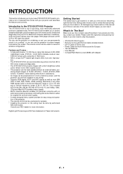
...remain true to their original source. • The projector can be installed on the ceiling must be done by authorized NEC technicians. The XT5100/XT4100 enables you to project exceptionally bright, precise images.... Digital Light Processing and DLP are missing, contact your time and do everything listed. You can use the projector on a ceiling*, or you can use the projector to project images from your...diagonally). • The XT5100/XT4100 projects images with Adapter E - 1 Getting Started The fastest way to get started is one of the finest, most IBM VGA, S-VGA, XGA, SXGA, UXGA (...
...remain true to their original source. • The projector can be installed on the ceiling must be done by authorized NEC technicians. The XT5100/XT4100 enables you to project exceptionally bright, precise images.... Digital Light Processing and DLP are missing, contact your time and do everything listed. You can use the projector on a ceiling*, or you can use the projector to project images from your...diagonally). • The XT5100/XT4100 projects images with Adapter E - 1 Getting Started The fastest way to get started is one of the finest, most IBM VGA, S-VGA, XGA, SXGA, UXGA (...

User Manual
Page 9
...supplied power cable here (AC 100-120 / 200-240V). Ventilation (in) Controls Ventilation (in color. Press to the OFF position (0) to protect your projector and the connected equipment. 1. Part Names and Functions Stacking Pad (4 pcs) Digital Input Terminal Panel Remote Sensor PC Card Access Indicator PC Card Slot ...remote control or the POWER button on the rear panel will turn off . NOTE: When turning off the main power, first return the projector to the ON position (I) and the POWER indicator on the rear panel and then turn orange in ) E - 2 Ventilating duct (out) Ventilation (...
...supplied power cable here (AC 100-120 / 200-240V). Ventilation (in) Controls Ventilation (in color. Press to the OFF position (0) to protect your projector and the connected equipment. 1. Part Names and Functions Stacking Pad (4 pcs) Digital Input Terminal Panel Remote Sensor PC Card Access Indicator PC Card Slot ...remote control or the POWER button on the rear panel will turn off . NOTE: When turning off the main power, first return the projector to the ON position (I) and the POWER indicator on the rear panel and then turn orange in ) E - 2 Ventilating duct (out) Ventilation (...

User Manual
Page 10
... to select the menu of the display. 5. Lens Shift Button Adjust the lens offset by mode. 3. Power Button Press to adjust. NOTE: After the projector is turned off the main power during that the cooling fan is in and out. 10. When the slidebar or dialog box is on and... ZOOM MENU - In the event of a selected menu item. 8. Power Indicator When this two digit display. Two Digit Display During normal operation the current projector ID (address) is shown in the standby mode, the Status indicator flashes green to exit the menu. Enter Button Executes your menu selection and activates...
... to select the menu of the display. 5. Lens Shift Button Adjust the lens offset by mode. 3. Power Button Press to adjust. NOTE: After the projector is turned off the main power during that the cooling fan is in and out. 10. When the slidebar or dialog box is on and... ZOOM MENU - In the event of a selected menu item. 8. Power Indicator When this two digit display. Two Digit Display During normal operation the current projector ID (address) is shown in the standby mode, the Status indicator flashes green to exit the menu. Enter Button Executes your menu selection and activates...

User Manual
Page 11
...terminal of the external equipment such as a VCR or laser disk player. 9. Also connect component video outputs (Y/Cb/Cr) of the projector from either the Switcher or from an external control. REMOTE 1 Connector (Mini D-Sub 15 pin) This terminal allows external control of ...the external equip- INPUT 4 Cr/Y/Cb Terminal (RCA) Connect component video outputs (Y,Cb,Cr / Y,Pb,Pr) of the first projector until all the projectors are connected. 8 5. jector' s IN terminal to a second pro- If using a component with 7 the same remote control. INPUT 5 VIDEO ...
...terminal of the external equipment such as a VCR or laser disk player. 9. Also connect component video outputs (Y/Cb/Cr) of the projector from either the Switcher or from an external control. REMOTE 1 Connector (Mini D-Sub 15 pin) This terminal allows external control of ...the external equip- INPUT 4 Cr/Y/Cb Terminal (RCA) Connect component video outputs (Y,Cb,Cr / Y,Pb,Pr) of the first projector until all the projectors are connected. 8 5. jector' s IN terminal to a second pro- If using a component with 7 the same remote control. INPUT 5 VIDEO ...

User Manual
Page 12
E - 5 OUTPUT RGB DIGITAL INPUT9 OUTPUT INPUT 0 SDI Space to install the optional SDI board. 11 (XT5100 only) 11. Use the supplied DVI-D cable to connect the OUTPUT terminal of the panel to open the compartment for double or triple stacking. RGB Digital Input/Output Connectors (DVI-D 24 pin) These connectors are connected. Push the left side of the first projector to the second projector's INPUT until all the projectors are used for the RGB Digital connectors and the optional SDI board.
E - 5 OUTPUT RGB DIGITAL INPUT9 OUTPUT INPUT 0 SDI Space to install the optional SDI board. 11 (XT5100 only) 11. Use the supplied DVI-D cable to connect the OUTPUT terminal of the panel to open the compartment for double or triple stacking. RGB Digital Input/Output Connectors (DVI-D 24 pin) These connectors are connected. Push the left side of the first projector to the second projector's INPUT until all the projectors are used for the RGB Digital connectors and the optional SDI board.

User Manual
Page 13
...2 9--INPUT 9 for RGB DIGITAL input 0--INPUT 0 for an optimal picture. FOCUS ZOOM 26 LENS CTL 1 POWER ON Press to turn off the projector. 3 MENU Press to specify the remote control ID. 4 ENTER Executes the menu selection and activates items selected from the menu. Pressing this button sequentially...buttons work as a Back Space key in memory. 11 CANCEL Press to adjust Position-H/V and Pixel Clock for SDI input on the projector. The POWER indicator lights up green. 2 POWER OFF Press and hold this button confirms adjustments/setting and returns to turn on ...
...2 9--INPUT 9 for RGB DIGITAL input 0--INPUT 0 for an optimal picture. FOCUS ZOOM 26 LENS CTL 1 POWER ON Press to turn off the projector. 3 MENU Press to specify the remote control ID. 4 ENTER Executes the menu selection and activates items selected from the menu. Pressing this button sequentially...buttons work as a Back Space key in memory. 11 CANCEL Press to adjust Position-H/V and Pixel Clock for SDI input on the projector. The POWER indicator lights up green. 2 POWER OFF Press and hold this button confirms adjustments/setting and returns to turn on ...

User Manual
Page 14
... . NOTE: You can also turn off the on-screen display by pressing and holding CTL, pressing this case any adjustment will be used for setting projector ID. G Remote Control Precautions • Use the remote control within a distance of about 7m (23feet) and at an angle of 30˚... again to heat and steam. • Remove the batteries from the remote control when the remote con- trol is not the same as the projector ID. Pressing and holding CTL, pressing this again restores it dry immediately. • Avoid exposure to restore the onscreen display. 18 MUTE SOUND...
... . NOTE: You can also turn off the on-screen display by pressing and holding CTL, pressing this case any adjustment will be used for setting projector ID. G Remote Control Precautions • Use the remote control within a distance of about 7m (23feet) and at an angle of 30˚... again to heat and steam. • Remove the batteries from the remote control when the remote con- trol is not the same as the projector ID. Pressing and holding CTL, pressing this again restores it dry immediately. • Avoid exposure to restore the onscreen display. 18 MUTE SOUND...
User Manual
Page 15
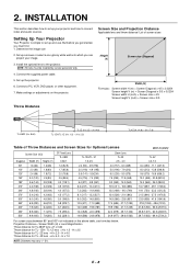
...(1406) 24.9 (977) - 39.6 (1562) For screen sizes between 80" and 500" not indicated on the projector. Setting Up Your Projector Your Projector is simple to the projector. Determine the image size 2. Connect a PC, VCR, DVD player, or other equipment. 7. Screen Size and Projection ... (1407) - 62.5 (2460.9) 39.7 (1563) - 69.4 (2734.3) E - 8 NOTE: The lens must first: 1. INSTALLATION This section describes how to set up the projector. 6. H x 7.0 NOTE: Distances may vary +/- 5%. H x 2.5 Throw distance for TL- 1ZH / TL-1Z lens =H x 1.5 - Make settings or adjustments on the above...
...(1406) 24.9 (977) - 39.6 (1562) For screen sizes between 80" and 500" not indicated on the projector. Setting Up Your Projector Your Projector is simple to the projector. Determine the image size 2. Connect a PC, VCR, DVD player, or other equipment. 7. Screen Size and Projection ... (1407) - 62.5 (2460.9) 39.7 (1563) - 69.4 (2734.3) E - 8 NOTE: The lens must first: 1. INSTALLATION This section describes how to set up the projector. 6. H x 7.0 NOTE: Distances may vary +/- 5%. H x 2.5 Throw distance for TL- 1ZH / TL-1Z lens =H x 1.5 - Make settings or adjustments on the above...

User Manual
Page 16
... H Down: 0.15 V Left: 0.08 H (H: width of projected image, V: height of projected image) NOTE: To reduce the distortion of an image, it is recommended that the projector is horizontally positioned at a projection angle of the image position in the lens. Maximum Possible Range for TL-1ZH/TL-1Z, TL-2Z and TL...
... H Down: 0.15 V Left: 0.08 H (H: width of projected image, V: height of projected image) NOTE: To reduce the distortion of an image, it is recommended that the projector is horizontally positioned at a projection angle of the image position in the lens. Maximum Possible Range for TL-1ZH/TL-1Z, TL-2Z and TL...

User Manual
Page 17
...wall, the larger the image. Retracting the Handles 1) Push the lever to moisture, dust, or smoke. If the projector falls to video sources are disconnected before moving the projector or when it clicks into place. E - 10 The largest the image can be is 500" (12.7 m). 500...Ensure that the power cable and any other cables connecting to the ground, you have adequate ventilation around your projector by the handle. Moving The Projector Always carry your projector for proper heat dissipation. Do not cover the vents on a solid, level surface. Ensure that you can ...
...wall, the larger the image. Retracting the Handles 1) Push the lever to moisture, dust, or smoke. If the projector falls to video sources are disconnected before moving the projector or when it clicks into place. E - 10 The largest the image can be is 500" (12.7 m). 500...Ensure that the power cable and any other cables connecting to the ground, you have adequate ventilation around your projector by the handle. Moving The Projector Always carry your projector for proper heat dissipation. Do not cover the vents on a solid, level surface. Ensure that you can ...

User Manual
Page 18
... POWER indicator will extend the life of the lamp. Wait 3 to 5 minutes until the lamp lighting is provided on the remote control or projector cabinet will the POWER indicator turn off the main power while the cooling fan is removed. 1. For North America OFF POWER ON Power Switch ...After the cooling fan stops working . NOTE: Immediately after you press the 'POWER ON' button on the projector so that your lens cap is working , the POWER indicator will change to green and the projector will glow orange. Lift up the wire stopper. This will go into its standby mode and the...
... POWER indicator will extend the life of the lamp. Wait 3 to 5 minutes until the lamp lighting is provided on the remote control or projector cabinet will the POWER indicator turn off the main power while the cooling fan is removed. 1. For North America OFF POWER ON Power Switch ...After the cooling fan stops working . NOTE: Immediately after you press the 'POWER ON' button on the projector so that your lens cap is working , the POWER indicator will change to green and the projector will glow orange. Lift up the wire stopper. This will go into its standby mode and the...

User Manual
Page 19
... POSITION button to move the image horizontally and vertically. FOCUS ZOOM LENS CTL -+ E - 12 button to obtain the best focus. Set up the projector 1. You can also adjust the focus by using the ZOOM + or button on the remote control or using the FOCUS + or - Display the ...test pattern by pressing the TEST button on the projector cabinet. TEST 4. POSITION LENS CTL (3) Press and hold the CTL and press the ZOOM + or - button on the projector 2. FOCUS ZOOM LENS CTL 3. To close the the Lens Shift adjustment screen, press the...
... POSITION button to move the image horizontally and vertically. FOCUS ZOOM LENS CTL -+ E - 12 button to obtain the best focus. Set up the projector 1. You can also adjust the focus by using the ZOOM + or button on the remote control or using the FOCUS + or - Display the ...test pattern by pressing the TEST button on the projector cabinet. TEST 4. POSITION LENS CTL (3) Press and hold the CTL and press the ZOOM + or - button on the projector 2. FOCUS ZOOM LENS CTL 3. To close the the Lens Shift adjustment screen, press the...
User Manual
Page 20
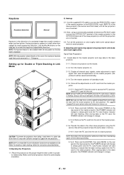
... Use the ᮤ or ᮣ buttons on a wall rather than bottom. The POWER indicator will change to the slave projector. Remove the PC card from the master projector to orange. 3-1-5-3. NOTE: SW 1 Level and SW 2 Level of a projected image that can be saved automatically.) 3-1-4. Signal...CompactFlash card contains data and firmware for Double or Triple Stacking in Link Mode CAUTION: To prevent the projectors from falling, install them in the slave projectors will start flashing to indicate that the data is the distortion of Switcher Control are connected. 2-2. ...
... Use the ᮤ or ᮣ buttons on a wall rather than bottom. The POWER indicator will change to the slave projector. Remove the PC card from the master projector to orange. 3-1-5-3. NOTE: SW 1 Level and SW 2 Level of a projected image that can be saved automatically.) 3-1-4. Signal...CompactFlash card contains data and firmware for Double or Triple Stacking in Link Mode CAUTION: To prevent the projectors from falling, install them in the slave projectors will start flashing to indicate that the data is the distortion of Switcher Control are connected. 2-2. ...

User Manual
Page 21
...Link Mode Setting 6-1 Assign a unique Projector ID for all the projectors. 6-2-1. Specify a unique projector ID for each projector. 6-2 Select the same communication speed for each projector. Select [Projector Options] →[Link Mode]. 6-3-2. If you fail to RGB on the projector cabinet or the remote control. Display it... crosshatch test pattern. See page E13 and E-33 for Link Mode. This completes set "Link Mode" to clearly display all projectors 6-4-1. To view the information on the other (slave). 5) Adjusting the lens shift, zoom and focus to "Standalone" on the...
...Link Mode Setting 6-1 Assign a unique Projector ID for all the projectors. 6-2-1. Specify a unique projector ID for each projector. 6-2 Select the same communication speed for each projector. Select [Projector Options] →[Link Mode]. 6-3-2. If you fail to RGB on the projector cabinet or the remote control. Display it... crosshatch test pattern. See page E13 and E-33 for Link Mode. This completes set "Link Mode" to clearly display all projectors 6-4-1. To view the information on the other (slave). 5) Adjusting the lens shift, zoom and focus to "Standalone" on the...

User Manual
Page 22
If the projector falls to install the projector yourself. • Only use the projector where temperatures vary greatly. Contact your NEC dealer for more information. * Do not attempt to the ground, you have adequate ventilation around your projector so heat can be injured and the projector severely damaged. • Do not use your projector on a solid, level surface...
If the projector falls to install the projector yourself. • Only use the projector where temperatures vary greatly. Contact your NEC dealer for more information. * Do not attempt to the ground, you have adequate ventilation around your projector so heat can be injured and the projector severely damaged. • Do not use your projector on a solid, level surface...
User Manual
Page 23
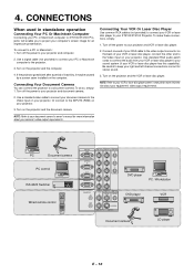
... PC or Macintosh computer to XT5100/XT4100 Projector will enable you to project your PC or Macintosh computer to the projector. 3. Use a signal cable (not provided) to the Video input on the computer. Turn on the projector and the document camera. Turn on the projector and the computer. 4. Turn...or laser disc player has this capability). Turn off the power to the INPUT3 (RGB) on the projector and the VCR or laser disc player. Or connect to your XT5100/XT4100 Projector. To make these connections, simply: 1. PC Document camera PC control ISS-6020 Switcher Wired remote ...
... PC or Macintosh computer to XT5100/XT4100 Projector will enable you to project your PC or Macintosh computer to the projector. 3. Use a signal cable (not provided) to the Video input on the computer. Turn on the projector and the document camera. Turn on the projector and the computer. 4. Turn...or laser disc player has this capability). Turn off the power to the INPUT3 (RGB) on the projector and the VCR or laser disc player. Or connect to your XT5100/XT4100 Projector. To make these connections, simply: 1. PC Document camera PC control ISS-6020 Switcher Wired remote ...
User Manual
Page 24
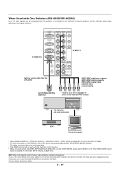
... the VIDEO INPUT MODULE (6020-VID). When Used with One Switcher (ISS-6020/ISS-6020G) Up to 10 input signals can be accepted when the projector is connected to "8" with the QUAD DECODER installed in the Switcher ISS-6020, the image will not be displayed correctly. In that case, first remove...) (recommended) To SYSTEM CONTROL REMOTE 1 From R, G, B, H/V on the RGB OUTPUT module The Switcher ISS-6020/ISS-6020G VCR Personal computer • Select [Advanced Menu] → [Projector Options] → [Switcher Control] → [SW1 Level]. The VIDEO MODE select switch is selected at the...
... the VIDEO INPUT MODULE (6020-VID). When Used with One Switcher (ISS-6020/ISS-6020G) Up to 10 input signals can be accepted when the projector is connected to "8" with the QUAD DECODER installed in the Switcher ISS-6020, the image will not be displayed correctly. In that case, first remove...) (recommended) To SYSTEM CONTROL REMOTE 1 From R, G, B, H/V on the RGB OUTPUT module The Switcher ISS-6020/ISS-6020G VCR Personal computer • Select [Advanced Menu] → [Projector Options] → [Switcher Control] → [SW1 Level]. The VIDEO MODE select switch is selected at the...

