

VP4001 .pcf File
Page 8
... Only A L R E _ _ _ 1 OK or ERR ERR Company Restricted VP4001 RS-232C Control Specification Page: 8 / 15 Document Version [1.0] Function SPECIAL DISPLAY Mode *1 Special Mode:1 Special Mode:2 Special Mode:3 Special Mode:4 Special Mode:5 Check LAMP STATUS Lamp Status Check Check PROJECTOR STATUS Abnormal Status Check Check CURRENT INPUT Input Check Check LAMP STATUS Power Status Check Check LAMP TIME Check LAMP LIFE Check MODEL NAME RESET ALL Lamp Elapsed Time Display Lamp Life (%) Display Model Name Check All Reset Code Command Parameter "_" is Space "*" is value C1 C2...
... Only A L R E _ _ _ 1 OK or ERR ERR Company Restricted VP4001 RS-232C Control Specification Page: 8 / 15 Document Version [1.0] Function SPECIAL DISPLAY Mode *1 Special Mode:1 Special Mode:2 Special Mode:3 Special Mode:4 Special Mode:5 Check LAMP STATUS Lamp Status Check Check PROJECTOR STATUS Abnormal Status Check Check CURRENT INPUT Input Check Check LAMP STATUS Power Status Check Check LAMP TIME Check LAMP LIFE Check MODEL NAME RESET ALL Lamp Elapsed Time Display Lamp Life (%) Display Model Name Check All Reset Code Command Parameter "_" is Space "*" is value C1 C2...

VP4001 User Manual
Page 2
... OPERATION, NEVER TURN THE PROJECTOR OFF BY DISCONNECTING THE POWER CORD. Model No.: VP4001 Serial No.: WARNING: High brightness light source. CAUTION RISK OF ELECTRIC SHOCK. The exclamation point within an equilateral triangle, is intended to alert the user to operate this equipment not expressly approved by the manufacturer could void the user's authority to the presence of "Supplied accessories" on the remote control. See bottom of light, or view...
... OPERATION, NEVER TURN THE PROJECTOR OFF BY DISCONNECTING THE POWER CORD. Model No.: VP4001 Serial No.: WARNING: High brightness light source. CAUTION RISK OF ELECTRIC SHOCK. The exclamation point within an equilateral triangle, is intended to alert the user to operate this equipment not expressly approved by the manufacturer could void the user's authority to the presence of "Supplied accessories" on the remote control. See bottom of light, or view...

VP4001 User Manual
Page 4
...to Read this User Guide I The specifications are simplified for using the buttons on the model. Using the Menu Screen TEMP. Buttons used in the same manner. • In this step On-screen display Info ........Indicates safeguards for explanation, and may differ slightly from the actual display. INPUT ENTER ASPECT MENU INPUT LAMP STANDBY/ON INPUT MENU ENTER ASPECT INPUT STANDBY ON COMP.1 COMP.2 S-VIDEO C1 C2 S VIDEO RGB HDMI V RGB HDMI KEYSTONE MENU Adjustment buttons (P/R/O/Q) MENU MENU button ENTER ENTER button RETURN ENTER AUTO SYNC SYNC ASPECT A RGB/COMP...
...to Read this User Guide I The specifications are simplified for using the buttons on the model. Using the Menu Screen TEMP. Buttons used in the same manner. • In this step On-screen display Info ........Indicates safeguards for explanation, and may differ slightly from the actual display. INPUT ENTER ASPECT MENU INPUT LAMP STANDBY/ON INPUT MENU ENTER ASPECT INPUT STANDBY ON COMP.1 COMP.2 S-VIDEO C1 C2 S VIDEO RGB HDMI V RGB HDMI KEYSTONE MENU Adjustment buttons (P/R/O/Q) MENU MENU button ENTER ENTER button RETURN ENTER AUTO SYNC SYNC ASPECT A RGB/COMP...
VP4001 User Manual
Page 5
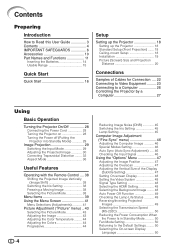
...16 Setup Setting up the Projector 18 Setting up the Projector 18 Standard Setup (Front Projection) ....... 18 Ceiling-mount Setup 18 Installation 19 Picture (Screen) Size and Projection Distance 20 Connections Samples of Cables for Connection .... 22 Connecting to Video Equipment ......... 23 Connecting to a Computer 26 Controlling the Projector by a Computer 27 Using Basic Operation Turning the Projector On/Off 28 Connecting the Power Cord 28 Turning the Projector on 28 Turning the Power off (Putting the Projector into Standby Mode 29 Image Projection 29 Switching the Input Mode...
...16 Setup Setting up the Projector 18 Setting up the Projector 18 Standard Setup (Front Projection) ....... 18 Ceiling-mount Setup 18 Installation 19 Picture (Screen) Size and Projection Distance 20 Connections Samples of Cables for Connection .... 22 Connecting to Video Equipment ......... 23 Connecting to a Computer 26 Controlling the Projector by a Computer 27 Using Basic Operation Turning the Projector On/Off 28 Connecting the Power Cord 28 Turning the Projector on 28 Turning the Power off (Putting the Projector into Standby Mode 29 Image Projection 29 Switching the Input Mode...

VP4001 User Manual
Page 9
... sure to prevent overheat damage. This will automatically put the projector into standby mode to occasionally rest your eyes occasionally. Observe the following safeguards when setting up your nearest Marantz Authorized Dealer or Service Center for replacement. I The operating temperature of temperature. See "Replacing the Lamp" on the screen washes out the colors, making viewing difficult. I Be sure that this can affect the longevity of...
... sure to prevent overheat damage. This will automatically put the projector into standby mode to occasionally rest your eyes occasionally. Observe the following safeguards when setting up your nearest Marantz Authorized Dealer or Service Center for replacement. I The operating temperature of temperature. See "Replacing the Lamp" on the screen washes out the colors, making viewing difficult. I Be sure that this can affect the longevity of...

VP4001 User Manual
Page 10
... other audio- Temperature monitor function I Do not carry the projector by holding the lens. Refer to the projector, make the connections. Unplug the power cord after the cooling fan stops. Using the projector in . ing indicator on the circumstances and the internal temperature. The sound of the fan may affect the cabinet color or cause deformation of the picture. visual equipment to "Maintenance Indicators" on page 52 for instructions...
... other audio- Temperature monitor function I Do not carry the projector by holding the lens. Refer to the projector, make the connections. Unplug the power cord after the cooling fan stops. Using the projector in . ing indicator on the circumstances and the internal temperature. The sound of the fan may affect the cabinet color or cause deformation of the picture. visual equipment to "Maintenance Indicators" on page 52 for instructions...

VP4001 User Manual
Page 14
... IMAGE SHIFT buttons For shifting the projected image vertically. button 48 For switching to a computer. AUTO SYNC button 46 For automatically adjusting images when connected to the respective input signal type. Using the Kensington Lock on the projector • This projector has a Kensington Security Standard connector for use with the system for instructions on . FREEZE button 38 For freezing images. IMAGE SHIFT PICTURE MODE R/C PIC FREEZE IRIS IRIS LIGHT 29 Comp. 1, Comp. 2, S-Video, Video, RGB and HDMI buttons For switching to...
... IMAGE SHIFT buttons For shifting the projected image vertically. button 48 For switching to a computer. AUTO SYNC button 46 For automatically adjusting images when connected to the respective input signal type. Using the Kensington Lock on the projector • This projector has a Kensington Security Standard connector for use with the system for instructions on . FREEZE button 38 For freezing images. IMAGE SHIFT PICTURE MODE R/C PIC FREEZE IRIS IRIS LIGHT 29 Comp. 1, Comp. 2, S-Video, Video, RGB and HDMI buttons For switching to...
VP4001 User Manual
Page 17
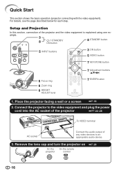
... ENTER AUTO SYNC SYNC ASPECT A RGB/COMP. Remove the lens cap and turn the projector on On the projector On the remote control ON \P. 28 16 Place the projector facing a wall or a screen \P. 18 2. For details, see the page described below for each step. Setup and Projection In this section, connection of the projector \PP. 22-28 STANDBY/ON LAMP INPUT TEMP. IMAGE SHIFT PICTURE MODE R/C PIC FREEZE IRIS IRIS LIGHT 7 Adjustment (P/R/O/Q) buttons 7 ENTER button 1. Connect the projector to...
... ENTER AUTO SYNC SYNC ASPECT A RGB/COMP. Remove the lens cap and turn the projector on On the projector On the remote control ON \P. 28 16 Place the projector facing a wall or a screen \P. 18 2. For details, see the page described below for each step. Setup and Projection In this section, connection of the projector \PP. 22-28 STANDBY/ON LAMP INPUT TEMP. IMAGE SHIFT PICTURE MODE R/C PIC FREEZE IRIS IRIS LIGHT 7 Adjustment (P/R/O/Q) buttons 7 ENTER button 1. Connect the projector to...

VP4001 User Manual
Page 18
... turning the zoom ring. Adjust the projector angle using the INPUT buttons on the projector or the VIDEO button on the remote control to also set and setup will be set the upper-right, lower-right, and lower-left position of the projected image. • When you to switch the input mode. 6. LAMP Focus ring 7. Press c KEYSTONE on and start playback 5. Adjust the focus, image size, and projector angle \PP. 30, 31 1. ASPECT INPUT MENU ENTER STANDBY/ON INPUT TEMP. Press P/R/O/Q on the remote control. Turn the Power...
... turning the zoom ring. Adjust the projector angle using the INPUT buttons on the projector or the VIDEO button on the remote control to also set and setup will be set the upper-right, lower-right, and lower-left position of the projected image. • When you to switch the input mode. 6. LAMP Focus ring 7. Press c KEYSTONE on and start playback 5. Adjust the focus, image size, and projector angle \PP. 30, 31 1. ASPECT INPUT MENU ENTER STANDBY/ON INPUT TEMP. Press P/R/O/Q on the remote control. Turn the Power...
VP4001 User Manual
Page 28
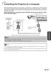
... RS-232C terminal STANDBY/ON LAMP INPUT TEMP. Refer to the user guide of the computer for details. • See page 58 for detail. Connections 27 Info • Do not connect the RS-232C cable to a computer using an RS-232C serial control cable and a DIN- This may damage your computer or projector. • Do not connect or disconnect an RS-232C serial control cable to or from...
... RS-232C terminal STANDBY/ON LAMP INPUT TEMP. Refer to the user guide of the computer for details. • See page 58 for detail. Connections 27 Info • Do not connect the RS-232C cable to a computer using an RS-232C serial control cable and a DIN- This may damage your computer or projector. • Do not connect or disconnect an RS-232C serial control cable to or from...

VP4001 User Manual
Page 29
... power cord is firmly connected into standby mode and immediately turned on the remote control. Supplied accessory Power cord STANDBY/ON LAMP INPUT TEMP. INPUT ENTER Lamp indicator Power indicator Note • About the Lamp Indicator The lamp indicator illuminates to indicate the status of the projector. Red:The lamp is on the projector, a slight flickering of the image may take some time to 28.) Remove the lens cap and press / I STANDBY/ON button ASPECT INPUT MENU ENTER STANDBY/ON INPUT TEMP. Info • English is put into the AC IN socket. Green...
... power cord is firmly connected into standby mode and immediately turned on the remote control. Supplied accessory Power cord STANDBY/ON LAMP INPUT TEMP. INPUT ENTER Lamp indicator Power indicator Note • About the Lamp Indicator The lamp indicator illuminates to indicate the status of the projector. Red:The lamp is on the projector, a slight flickering of the image may take some time to 28.) Remove the lens cap and press / I STANDBY/ON button ASPECT INPUT MENU ENTER STANDBY/ON INPUT TEMP. Info • English is put into the AC IN socket. Green...

VP4001 User Manual
Page 41
...ês Menu Items (Continued) "Fine Sync" menu Fine Sync Clock Phase H-Pos V-Pos Reset Special Modes Auto Sync RGB 0 0 0 0 1080I On Cur. "Options1" menu Options 1 Image Shift Overscan H Overscan V Subtitle OSD Display Video System Signal Type HDMI Setting Background Auto Power Off Lamp Timer(Life) SEL./ADJ. RETURN Comp. 1 0 0 0 0 On Auto Auto Normal Blue On 0h 100% ENTER END *1 Item that can be set when using S-Video or Video. *2 Item that can be set when using RGB or HDMI. sig...
...ês Menu Items (Continued) "Fine Sync" menu Fine Sync Clock Phase H-Pos V-Pos Reset Special Modes Auto Sync RGB 0 0 0 0 1080I On Cur. "Options1" menu Options 1 Image Shift Overscan H Overscan V Subtitle OSD Display Video System Signal Type HDMI Setting Background Auto Power Off Lamp Timer(Life) SEL./ADJ. RETURN Comp. 1 0 0 0 0 On Auto Auto Normal Blue On 0h 100% ENTER END *1 Item that can be set when using S-Video or Video. *2 Item that can be set when using RGB or HDMI. sig...

VP4001 User Manual
Page 44
...S. Progressive DNR IRIS Lamp Setting Reset Menu operation = Page 41 7500K 1 Comp. 1 Standard 3D Progressive Level 1 WIDE Normal 1 Selecting the Picture Mode Selectable items Standard Natural Dynamic Theater 1 Theater 2 Memory Description For standard image A balanced color image is obtained. Useful Features 43 Picture Adjustment ("Picture" menu) Q PAGE 1 Picture Picture Mode Contrast Bright Color Tint Sharp Red Blue Comp. 1 Standard 0 0 0 0 0 0 0 Q PAGE 2 Picture Picture Mode CLR Temp BrilliantColor™ C. Note • You can set or adjust each input mode. For more...
...S. Progressive DNR IRIS Lamp Setting Reset Menu operation = Page 41 7500K 1 Comp. 1 Standard 3D Progressive Level 1 WIDE Normal 1 Selecting the Picture Mode Selectable items Standard Natural Dynamic Theater 1 Theater 2 Memory Description For standard image A balanced color image is obtained. Useful Features 43 Picture Adjustment ("Picture" menu) Q PAGE 1 Picture Picture Mode Contrast Bright Color Tint Sharp Red Blue Comp. 1 Standard 0 0 0 0 0 0 0 Q PAGE 2 Picture Picture Mode CLR Temp BrilliantColor™ C. Note • You can set or adjust each input mode. For more...

VP4001 User Manual
Page 49
... Blue screen - (Black screen) 48 INPUT/FREEZE/AUTO SYNC/ASPECT/ PICTURE MODE/IRIS are displayed. Note • You can also select "Signal Type" using R/C RGB/COMP. When reproducing NTSC signals in PAL video equipment. When connected to select the input signal type (RGB or Component) for RGB or HDMI. When there is factory preset to "Auto";however, a clear picture from the connected audio-visual equipment may not be received, depending on the remote control...
... Blue screen - (Black screen) 48 INPUT/FREEZE/AUTO SYNC/ASPECT/ PICTURE MODE/IRIS are displayed. Note • You can also select "Signal Type" using R/C RGB/COMP. When reproducing NTSC signals in PAL video equipment. When connected to select the input signal type (RGB or Component) for RGB or HDMI. When there is factory preset to "Auto";however, a clear picture from the connected audio-visual equipment may not be received, depending on the remote control...
VP4001 User Manual
Page 50
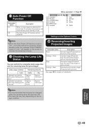
... no input signal is detected for details of the screen or with a mirror) Reversed and inverted image (Projected with a mirror) See page 19 for more than 15 minutes, the projector will appear on the screen to indicate the remaining minutes. 0 Checking the Lamp Life Status You can confirm the cumulative lamp usage time and the remaining lamp life (percentage). The Auto Power Off function will be changed when the remaining lamp life...
... no input signal is detected for details of the screen or with a mirror) Reversed and inverted image (Projected with a mirror) See page 19 for more than 15 minutes, the projector will appear on the screen to indicate the remaining minutes. 0 Checking the Lamp Life Status You can confirm the cumulative lamp usage time and the remaining lamp life (percentage). The Auto Power Off function will be changed when the remaining lamp life...

VP4001 User Manual
Page 54
... Green blinks (Cooling) Red blinks The power indicator blinks in red even when the lamp unit cover is controlled automatically. The cooling fan runs for repair. • Please exercise care when replacing the lamp. • Securely install the cover. • If the power indicator blinks in red when the projector is on. Appendix 53 Maintenance indicator Temperature warning indicator Normal Off Abnormal Red on (Standby) Problem The internal temperature is open. Cause • Blocked air intake • Cooling fan breakdown • Internal circuit failure...
... Green blinks (Cooling) Red blinks The power indicator blinks in red even when the lamp unit cover is controlled automatically. The cooling fan runs for repair. • Please exercise care when replacing the lamp. • Securely install the cover. • If the power indicator blinks in red when the projector is on. Appendix 53 Maintenance indicator Temperature warning indicator Normal Off Abnormal Red on (Standby) Problem The internal temperature is open. Cause • Blocked air intake • Cooling fan breakdown • Internal circuit failure...

VP4001 User Manual
Page 57
...power will not turn on the projector. • "LAMP 0000H" is displayed, indicating that the lamp timer is connected to the projector. Securing screws 2 1 Resetting the Lamp Timer Reset the lamp timer after replacing the lamp. INPUT ENTER ASPECT MENU INPUT / I STANDBY/ON on , even if the power cord is reset. 56 STANDBY/ON LAMP INPUT TEMP. Fasten the securing screws. 6 Replace the lamp unit cover. • Align the tab on the projector, press / I STANDBY/ ON button ENTER button MENU button R button If you reset the lamp timer and continue to use the same lamp, this time, keep...
...power will not turn on the projector. • "LAMP 0000H" is displayed, indicating that the lamp timer is connected to the projector. Securing screws 2 1 Resetting the Lamp Timer Reset the lamp timer after replacing the lamp. INPUT ENTER ASPECT MENU INPUT / I STANDBY/ON on , even if the power cord is reset. 56 STANDBY/ON LAMP INPUT TEMP. Fasten the securing screws. 6 Replace the lamp unit cover. • Align the tab on the projector, press / I STANDBY/ ON button ENTER button MENU button R button If you reset the lamp timer and continue to use the same lamp, this time, keep...
VP4001 User Manual
Page 61
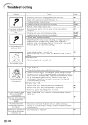
... lamp unit cover is not installed correctly. • Cables incorrectly connected to switch its signal output settings. Maintenance indicator on RGB (RGB)/HDMI (RGB). Color is faded or poor. • Adjust the focus. 30 • The projection distance exceeds the focus range. 20 Picture is due to "Color", "Tint" and "BrilliantColor™" in the "Options1" menu and change the input (Component)/HDMI signal type. (Component). 48 Picture is set up the projector at least one hour before...
... lamp unit cover is not installed correctly. • Cables incorrectly connected to switch its signal output settings. Maintenance indicator on RGB (RGB)/HDMI (RGB). Color is faded or poor. • Adjust the focus. 30 • The projection distance exceeds the focus range. 20 Picture is due to "Color", "Tint" and "BrilliantColor™" in the "Options1" menu and change the input (Component)/HDMI signal type. (Component). 48 Picture is set up the projector at least one hour before...

VP4001 User Manual
Page 62
... remote control cannot be used. • Operate the remote control while pointing it at the projector's remote control sensor. • The remote control may be adversely affected by strong light. • The batteries may be changed. The lamp suddenly turns off during projection. The cooling fan becomes • When temperature inside the projector increases, the cooling fan noisy. The lamp does not light • The lamp indicator is dark. projector turns on the projector's remote control sensor, place the projector...
... remote control cannot be used. • Operate the remote control while pointing it at the projector's remote control sensor. • The remote control may be adversely affected by strong light. • The batteries may be changed. The lamp suddenly turns off during projection. The cooling fan becomes • When temperature inside the projector increases, the cooling fan noisy. The lamp does not light • The lamp indicator is dark. projector turns on the projector's remote control sensor, place the projector...
VP4001 User Manual
Page 65
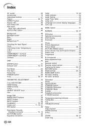
... GEOMETRIC ADJUSTMENT 34 H & V KEYSTONE 35 HDMI Setting 48 HDMI terminal 25 H-Pos 46 HEIGHT ADJUST lever 30 Hue 44 Image Shift 47 IMAGE SHIFT buttons 38 INPUT modes 29 INPUT buttons 29 Installation 19, 49 Intake vent 11, 12, 51 IRIS button 38 Kensington Security Standard connector 12, 13 KEYSTONE button 32 Keystone Correction 32 Lamp 10, 54 Lamp indicator 52 Lamp Setting 45 Lamp Timer (Life 49 Lamp unit 55 Language (on-screen display language) ...... 50 Lens cap 11 MENU button...
... GEOMETRIC ADJUSTMENT 34 H & V KEYSTONE 35 HDMI Setting 48 HDMI terminal 25 H-Pos 46 HEIGHT ADJUST lever 30 Hue 44 Image Shift 47 IMAGE SHIFT buttons 38 INPUT modes 29 INPUT buttons 29 Installation 19, 49 Intake vent 11, 12, 51 IRIS button 38 Kensington Security Standard connector 12, 13 KEYSTONE button 32 Keystone Correction 32 Lamp 10, 54 Lamp indicator 52 Lamp Setting 45 Lamp Timer (Life 49 Lamp unit 55 Language (on-screen display language) ...... 50 Lens cap 11 MENU button...


