Owners Manual English
Page 2
... Remotely connecting Marantz audio devices 15 Connecting the power cord 15 Playback 16 Turning the power on 16 Selecting the input source 16 Adjusting the volume 16 Turning off the sound temporarily (Muting 16 Adjusting the volume balance (LEVEL) and sound quality (BASS/ TREBLE 17 Switching the display's brightness 18 Having the illumination lamp off 18 Playing CDs 18 Recording 18 Settings 19 Menu map 19 Menu operation 19 PHONO 20 AUTO STBY (Auto Standby 20 ATT LEVEL (Attenuation Level 20 Tips 21 Tips 22 Troubleshooting 23 Error...
... Remotely connecting Marantz audio devices 15 Connecting the power cord 15 Playback 16 Turning the power on 16 Selecting the input source 16 Adjusting the volume 16 Turning off the sound temporarily (Muting 16 Adjusting the volume balance (LEVEL) and sound quality (BASS/ TREBLE 17 Switching the display's brightness 18 Having the illumination lamp off 18 Playing CDs 18 Recording 18 Settings 19 Menu map 19 Menu operation 19 PHONO 20 AUTO STBY (Auto Standby 20 ATT LEVEL (Attenuation Level 20 Tips 21 Tips 22 Troubleshooting 23 Error...
Owners Manual English
Page 4
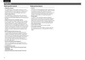
... high sound quality MELF resistors and film capacitors. 0 Double-layered chassis 0 High-grade copper machined analog audio input connectors (CD/PHONO only) 0 High-grade Machined Copper Speaker Terminals High performance 0 F.C.B.S. This switching amplifier module minimizes distortion from bass to treble and frequency characteristics are used to adjust the bass and treble volumes in 1 dB steps within a ±6 dB range. 3 A Floating Control Bus System (F.C.B.S.) enables the user to connect up to...
... high sound quality MELF resistors and film capacitors. 0 Double-layered chassis 0 High-grade copper machined analog audio input connectors (CD/PHONO only) 0 High-grade Machined Copper Speaker Terminals High performance 0 F.C.B.S. This switching amplifier module minimizes distortion from bass to treble and frequency characteristics are used to adjust the bass and treble volumes in 1 dB steps within a ±6 dB range. 3 A Floating Control Bus System (F.C.B.S.) enables the user to connect up to...
Owners Manual English
Page 5
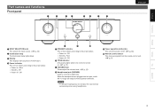
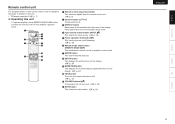
... lights when tone control is turned on : Off 0 Standby : Red 0 Power off . (v p. 16) J Remote control sensor This receives signals from the speaker terminals. NOTE 0 To prevent hearing loss, do not raise the volume level excessively when using headphones. Part names and functions Front panel q w er ty w u ENGLISH Overview Connections Playback Settings Tips Appendix . When the headphones are plugged into this jack, audio will no longer be output from the remote control unit. (v p. 2) 4 A INPUT SELECTOR knob This selects the input source...
... lights when tone control is turned on : Off 0 Standby : Red 0 Power off . (v p. 16) J Remote control sensor This receives signals from the speaker terminals. NOTE 0 To prevent hearing loss, do not raise the volume level excessively when using headphones. Part names and functions Front panel q w er ty w u ENGLISH Overview Connections Playback Settings Tips Appendix . When the headphones are plugged into this jack, audio will no longer be output from the remote control unit. (v p. 2) 4 A INPUT SELECTOR knob This selects the input source...
Owners Manual English
Page 6
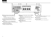
...connectors (POWER AMP IN) Used to connect a pre-amplifier when this unit is used as a power amplifier. (v p. 14) D Speaker terminals (SPEAKERS) Used to connect speakers. (v p. 8) E Remote control input/output connectors (REMOTE CONTROL) Used to connect to a Marantz audio device that is compatible with the remote control function. (v p. 15) F AMP MODE switch Used to switch the amplifier mode (STEREO/BIAMP). (v p. 11) G SIGNAL GND terminal Used to connect the ground wire of PM-KI RUBY units. (v p. 10) I AC inlet (AC IN) Used to set the ID number for F.C.B.S. (v p. 11) 5 ENGLISH Rear panel...
...connectors (POWER AMP IN) Used to connect a pre-amplifier when this unit is used as a power amplifier. (v p. 14) D Speaker terminals (SPEAKERS) Used to connect speakers. (v p. 8) E Remote control input/output connectors (REMOTE CONTROL) Used to connect to a Marantz audio device that is compatible with the remote control function. (v p. 15) F AMP MODE switch Used to switch the amplifier mode (STEREO/BIAMP). (v p. 11) G SIGNAL GND terminal Used to connect the ground wire of PM-KI RUBY units. (v p. 10) I AC inlet (AC IN) Used to set the ID number for F.C.B.S. (v p. 11) 5 ENGLISH Rear panel...
Owners Manual English
Page 7
D Input source select buttons (INPUT df) This selects the input source. (v p. 16) E Power operation button (X AMP) This turns the power on/off (standby). (v p. 16) F Remote mode select button (REMOTE MODE AMP) This switches the remote control to turn the illumination lamp on /off . H SETUP button This displays the setting menu on the display. (v p. 19) I MODE/TRIM button This displays the volume balance adjustment menu on the display. (v p. 17) J TONE button Turns the tone control function on /off . (v p. 17) K VOLUME buttons (df) These adjust the volume level. (v p. 16) L MUTE button This...
D Input source select buttons (INPUT df) This selects the input source. (v p. 16) E Power operation button (X AMP) This turns the power on/off (standby). (v p. 16) F Remote mode select button (REMOTE MODE AMP) This switches the remote control to turn the illumination lamp on /off . H SETUP button This displays the setting menu on the display. (v p. 19) I MODE/TRIM button This displays the volume balance adjustment menu on the display. (v p. 17) J TONE button Turns the tone control function on /off . (v p. 17) K VOLUME buttons (df) These adjust the volume level. (v p. 16) L MUTE button This...
Owners Manual English
Page 8
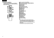
...) B Remote mode select button (REMOTE MODE CD) C Cursor buttons (uio p) D DISPLAY button E System buttons F Information button (INFO) G Number buttons (0 - 9, +10) H RANDOM button I REPEAT button J FILTER button K SOUND MODE button L ENTER button M SETUP button N MODE/TRIM button O OPEN/CLOSE button P DISC/INPUT button Q CLEAR button R PROGRAM button S DIGITAL OUT button 0 Basic amplifier operations such as switching the input source, trimming the volume and muting can be done even when CD is set as the remote control operation mode. 0 When using it, also refer to the CD player operation mode...
...) B Remote mode select button (REMOTE MODE CD) C Cursor buttons (uio p) D DISPLAY button E System buttons F Information button (INFO) G Number buttons (0 - 9, +10) H RANDOM button I REPEAT button J FILTER button K SOUND MODE button L ENTER button M SETUP button N MODE/TRIM button O OPEN/CLOSE button P DISC/INPUT button Q CLEAR button R PROGRAM button S DIGITAL OUT button 0 Basic amplifier operations such as switching the input source, trimming the volume and muting can be done even when CD is set as the remote control operation mode. 0 When using it, also refer to the CD player operation mode...
Owners Manual English
Page 9
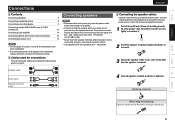
... to connect the channels and polarities correctly. When using a banana plug Tighten the speaker terminal firmly before connecting the speakers. 0 Connect so that the speaker cable core wires do not protrude from the power outlet before inserting the banana plug. . 8 Audio cable L L R R . Connecting speakers NOTE 0 Disconnect this unit, and be activated if the core wires touch the rear panel or if the + and - Speaker cable . connection) 10 Connecting a pre-amplifier 14 Connecting devices with remote control connectors 15 Connecting the power cord...
... to connect the channels and polarities correctly. When using a banana plug Tighten the speaker terminal firmly before connecting the speakers. 0 Connect so that the speaker cable core wires do not protrude from the power outlet before inserting the banana plug. . 8 Audio cable L L R R . Connecting speakers NOTE 0 Disconnect this unit, and be activated if the core wires touch the rear panel or if the + and - Speaker cable . connection) 10 Connecting a pre-amplifier 14 Connecting devices with remote control connectors 15 Connecting the power cord...
Owners Manual English
Page 10
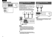
... effect of this unit. CD player AUDIO OUT RL Tuner AUDIO OUT RL Network audio player AUDIO OUT RL RL RL RL Connecting a recording device Recording device AUDIO OUT AUDIO IN RL RL RL RL RL RL CD LINE-1 LINE-2 RECORDER-1 RECORDER-2 RECORDER-1 RECORDER-2 AUDIO IN SIGNAL GND PHONO AUDIO OUT POWER AMP IN AUDIO IN SPEAKERS IMPEDANCE : 4㹼16Ȑ IN OUT STEREO BI-AMP REMOTE CONTROL AMP MODE IN OUT ID F.C.B.S. L R . AC IN...
... effect of this unit. CD player AUDIO OUT RL Tuner AUDIO OUT RL Network audio player AUDIO OUT RL RL RL RL Connecting a recording device Recording device AUDIO OUT AUDIO IN RL RL RL RL RL RL CD LINE-1 LINE-2 RECORDER-1 RECORDER-2 RECORDER-1 RECORDER-2 AUDIO IN SIGNAL GND PHONO AUDIO OUT POWER AMP IN AUDIO IN SPEAKERS IMPEDANCE : 4㹼16Ȑ IN OUT STEREO BI-AMP REMOTE CONTROL AMP MODE IN OUT ID F.C.B.S. L R . AC IN...
Owners Manual English
Page 11
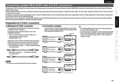
...). connection n Making the F.C.B.S. connection To use connecting cables that switches this connection in order of lowest to highest ID number, and switch the power OFF in addition to be set for the number of multiple PM-KI RUBY units has the feature that contain resistance. Signal flow ID 1 Master CD LINE-1 LINE-2 RECORDER-1 RECORDER-2 RECORDER-1 RECORDER-2 AUDIO IN SIGNAL GND PHONO AUDIO OUT POWER AMP IN AUDIO IN SPEAKERS IMPEDANCE : 4㹼16Ω IN OUT STEREO BI-AMP REMOTE CONTROL AMP MODE...
...). connection n Making the F.C.B.S. connection To use connecting cables that switches this connection in order of lowest to highest ID number, and switch the power OFF in addition to be set for the number of multiple PM-KI RUBY units has the feature that contain resistance. Signal flow ID 1 Master CD LINE-1 LINE-2 RECORDER-1 RECORDER-2 RECORDER-1 RECORDER-2 AUDIO IN SIGNAL GND PHONO AUDIO OUT POWER AMP IN AUDIO IN SPEAKERS IMPEDANCE : 4㹼16Ω IN OUT STEREO BI-AMP REMOTE CONTROL AMP MODE...
Owners Manual English
Page 12
... number. 0 For a master unit, ID number 1 needs to be used for F.C.B.S. connected PM-KI RUBY units are output from both channels. ID on the rear panel, press X. 2 Turn INPUT SELECTOR on the display. If this mode, two F.C.B.S. Stereo complete bi-amp connection This mode enables the two amplifiers connected to this unit by itself as one monaural amplifier. Before connecting your speakers, check in bi-amp mode, the signals input into the L channel are required. Settings can be used . 0 When in the instruction manual...
... number. 0 For a master unit, ID number 1 needs to be used for F.C.B.S. connected PM-KI RUBY units are output from both channels. ID on the rear panel, press X. 2 Turn INPUT SELECTOR on the display. If this mode, two F.C.B.S. Stereo complete bi-amp connection This mode enables the two amplifiers connected to this unit by itself as one monaural amplifier. Before connecting your speakers, check in bi-amp mode, the signals input into the L channel are required. Settings can be used . 0 When in the instruction manual...
Owners Manual English
Page 13
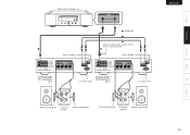
...Connections Playback Settings Tips R L : Signal flow L CD LINE-1 LINE-2 RECORDER-1 RECORDER-2 RECORDER-1 RECORDER-2 AUDIO IN SIGNAL GND PHONO AUDIO OUT POWER AMP IN AUDIO IN Set PM-KI RUBY for R channel to ID 2 Set to "BI-AMP". SPEAKERS IN OUT STEREO BI-AMP REMOTE CONTROL AMP MODE IN OUT ID F.C.B.S. SPEAKERS IN OUT STEREO BI-AMP REMOTE CONTROL AMP MODE IN OUT ID F.C.B.S. Super Audio CD player, etc. AC IN To power outlet. Set to the L channel input connector. Set PM-KI RUBY for L channel to ID 1 When in bi-amp mode, connect to "BI-AMP...
...Connections Playback Settings Tips R L : Signal flow L CD LINE-1 LINE-2 RECORDER-1 RECORDER-2 RECORDER-1 RECORDER-2 AUDIO IN SIGNAL GND PHONO AUDIO OUT POWER AMP IN AUDIO IN Set PM-KI RUBY for R channel to ID 2 Set to "BI-AMP". SPEAKERS IN OUT STEREO BI-AMP REMOTE CONTROL AMP MODE IN OUT ID F.C.B.S. SPEAKERS IN OUT STEREO BI-AMP REMOTE CONTROL AMP MODE IN OUT ID F.C.B.S. Super Audio CD player, etc. AC IN To power outlet. Set to the L channel input connector. Set PM-KI RUBY for L channel to ID 1 When in bi-amp mode, connect to "BI-AMP...
Owners Manual English
Page 14
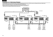
... the three amplifiers as explained in How to "STEREO". SACD multi-channel player, etc. CD LINE-1 LINE-2 RECORDER-1 RECORDER-2 RECORDER-1 RECORDER-2 AUDIO IN SIGNAL GND PHONO AUDIO OUT POWER AMP IN AUDIO IN SPEAKERS IN OUT STEREO BI-AMP REMOTE CONTROL AMP MODE IN OUT ID F.C.B.S. To power outlet. To power outlet. AC IN RL For surround speakers Set PM-KI RUBY to ID 3 Set to "STEREO". Front speaker (Left) Front speaker (Right) . 13 Center speaker Rear speaker (Left Surround) Rear speaker (Right Surround) If using an active subwoofer, see "Examples...
... the three amplifiers as explained in How to "STEREO". SACD multi-channel player, etc. CD LINE-1 LINE-2 RECORDER-1 RECORDER-2 RECORDER-1 RECORDER-2 AUDIO IN SIGNAL GND PHONO AUDIO OUT POWER AMP IN AUDIO IN SPEAKERS IN OUT STEREO BI-AMP REMOTE CONTROL AMP MODE IN OUT ID F.C.B.S. To power outlet. To power outlet. AC IN RL For surround speakers Set PM-KI RUBY to ID 3 Set to "STEREO". Front speaker (Left) Front speaker (Right) . 13 Center speaker Rear speaker (Left Surround) Rear speaker (Right Surround) If using an active subwoofer, see "Examples...
Owners Manual English
Page 15
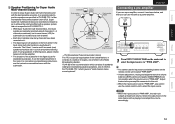
... which governs "multi-channel stereo sound systems". Settings Tips Appendix 14 It can use the input source switching buttons on the remote control unit to select "PWR AMP". 0 Volume adjustment, muting and adjustments to the volume balance (LEVEL) and sound quality (BASS/TREBLE) are not possible when the input source is the ITU-R BS.775-1 which consists of standards relating to select the input source. Super Audio CD multichannel discs are basically recorded using speakers of differing sizes, adjust volume balance from the amplifier. 0 The location...
... which governs "multi-channel stereo sound systems". Settings Tips Appendix 14 It can use the input source switching buttons on the remote control unit to select "PWR AMP". 0 Volume adjustment, muting and adjustments to the volume balance (LEVEL) and sound quality (BASS/TREBLE) are not possible when the input source is the ITU-R BS.775-1 which consists of standards relating to select the input source. Super Audio CD multichannel discs are basically recorded using speakers of differing sizes, adjust volume balance from the amplifier. 0 The location...
Owners Manual English
Page 16
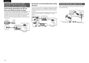
... you can connect an external IR receiver to the REMOTE CONTROL connectors to the device. Infrared retransmitter Infrared sensor RC OUT IN OUT REMOTE CONTROL IN OUT STEREO BI-AMP REMOTE CONTROL AMP MODE IN OUT ID F.C.B.S. Power cord (supplied) . 15 Set the remote control switch located on the rear panel of the connected audio component to "EXTERNAL" to use this unit with the supplied remote control unit without visual contact You can 't directly point with the...
... you can connect an external IR receiver to the REMOTE CONTROL connectors to the device. Infrared retransmitter Infrared sensor RC OUT IN OUT REMOTE CONTROL IN OUT STEREO BI-AMP REMOTE CONTROL AMP MODE IN OUT ID F.C.B.S. Power cord (supplied) . 15 Set the remote control switch located on the rear panel of the connected audio component to "EXTERNAL" to use this unit with the supplied remote control unit without visual contact You can 't directly point with the...
Owners Manual English
Page 17
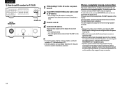
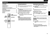
... is in standby mode to turn off the sound temporarily (Muting) 1 Press MUTE. ENGLISH Selecting the input source 1 Use INPUT df to select the input source to be decreased when MUTE is pressed. n Switching the power to standby mode, and the STANDBY indicator lights red. Set this as desired through "ATT LEVEL" in the standby mode. The unit switches to standby 1 Press X AMP on the remote control. The selected input source appears on the display. 0 You can also adjust the volume by turning INPUT SELECTOR on...
... is in standby mode to turn off the sound temporarily (Muting) 1 Press MUTE. ENGLISH Selecting the input source 1 Use INPUT df to select the input source to be decreased when MUTE is pressed. n Switching the power to standby mode, and the STANDBY indicator lights red. Set this as desired through "ATT LEVEL" in the standby mode. The unit switches to standby 1 Press X AMP on the remote control. The selected input source appears on the display. 0 You can also adjust the volume by turning INPUT SELECTOR on...
Owners Manual English
Page 18
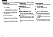
... enters TREBLE adjustment mode. 3 Press ui to adjust the treble volume. 0 If there is no operation for to adjust the volume balance (LEVEL) and sound quality (BASS/TREBLE) can be switched by pressing this button. 2 Press o p to select the channel that you wish to configure (L or R). Follow steps 3 onward of the left and right channels can be trimmed in 0.5 dB steps across a 0.0 - -9.0 dB range. The factory default setting is turned off . The factory default setting is connected by...
... enters TREBLE adjustment mode. 3 Press ui to adjust the treble volume. 0 If there is no operation for to adjust the volume balance (LEVEL) and sound quality (BASS/TREBLE) can be switched by pressing this button. 2 Press o p to select the channel that you wish to configure (L or R). Follow steps 3 onward of the left and right channels can be trimmed in 0.5 dB steps across a 0.0 - -9.0 dB range. The factory default setting is turned off . The factory default setting is connected by...
Owners Manual English
Page 19
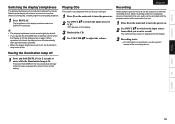
... Audio signals input into this unit. 1 Press X on the main unit to turn the power on operations, see the owner's manual of the recording device. Switching the display off reduces a source of the display switches each time DISPLAY is pressed. 0 The display brightness is displayed on the display. 3 Recording starts. 0 For information on . 2 Use INPUT df to switch the input source to "CD". Playing CDs This section uses playback from a playback device connected to this unit, audio...
... Audio signals input into this unit. 1 Press X on the main unit to turn the power on operations, see the owner's manual of the recording device. Switching the display off reduces a source of the display switches each time DISPLAY is pressed. 0 The display brightness is displayed on the display. 3 Recording starts. 0 For information on . 2 Use INPUT df to switch the input source to "CD". Playing CDs This section uses playback from a playback device connected to this unit, audio...
Owners Manual English
Page 23
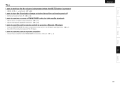
... of PM-KI RUBY units for high quality playback 0 Use the stereo complete bi-amp connections. (v p. 11) 0 Use the multi-channel playback connections. (v p. 13) I want to the POWER AMP IN connectors of the CD player. I want to use this unit's remote control to operate a Marantz CD player 0 Press the REMOTE MODE CD button to switch the remote control to the CD player operating mode. (v p. 7) 0 Also, refer to the instruction manual of this unit as a power amplifier 0 Connect the pre amplifier to use this unit. (v p. 14) ENGLISH Connections Playback Settings...
... of PM-KI RUBY units for high quality playback 0 Use the stereo complete bi-amp connections. (v p. 11) 0 Use the multi-channel playback connections. (v p. 13) I want to the POWER AMP IN connectors of the CD player. I want to use this unit's remote control to operate a Marantz CD player 0 Press the REMOTE MODE CD button to switch the remote control to the CD player operating mode. (v p. 7) 0 Also, refer to the instruction manual of this unit as a power amplifier 0 Connect the pre amplifier to use this unit. (v p. 14) ENGLISH Connections Playback Settings...
Owners Manual English
Page 25
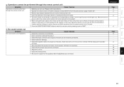
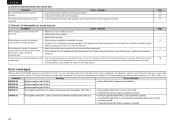
... the proper input source is selected. 0 Adjust the volume. 0 Cancel the muting mode. 0 No sound is exposed to strong light. 0 When using a 3D video device, the remote control unit of units with the metal part on speaker terminals. 0 Securely tighten the speaker terminals. Cause / Solution 0 Check the connections for all devices. 0 Insert connection cables all the way in. 0 Check that input connectors and output connectors are not reversely connected. 0 Check cables for...
... the proper input source is selected. 0 Adjust the volume. 0 Cancel the muting mode. 0 No sound is exposed to strong light. 0 When using a 3D video device, the remote control unit of units with the metal part on speaker terminals. 0 Securely tighten the speaker terminals. Cause / Solution 0 Check the connections for all devices. 0 Insert connection cables all the way in. 0 Check that input connectors and output connectors are not reversely connected. 0 Check cables for...
Owners Manual English
Page 26
... playing a record, the sound is properly connected. 25 Indication Meaning Cause / Solution ERROR 02 Multiple amplifiers take ID No.1, set ID number for F.C.B.S." (v p. 11). The left and right channel balance. Use cushions, etc., to the correct speaker terminals. Audio sources recorded through the floor. ENGLISH n Desired sound does not come out Symptom Cause / Solution No sound comes out of a specific speaker. 0 Check that is high. (Howling phenomenon) 0 Install...
... playing a record, the sound is properly connected. 25 Indication Meaning Cause / Solution ERROR 02 Multiple amplifiers take ID No.1, set ID number for F.C.B.S." (v p. 11). The left and right channel balance. Use cushions, etc., to the correct speaker terminals. Audio sources recorded through the floor. ENGLISH n Desired sound does not come out Symptom Cause / Solution No sound comes out of a specific speaker. 0 Check that is high. (Howling phenomenon) 0 Install...


