
User Guide
Page 3
... guide, BIOS updates, driver updates, and other information: http://www.msi.com.tw/program/service/faq/faq/esc_faq_list.php Contact our technical staff at: support@msi.com.tw iii AMI® is a registered trademark of Phoenix Technologies Ltd. Award® is a registered trademark of American Megatrends Inc. Windows®... make changes without notice. Copyright Notice The material in the preparation of this document is the intellectual property of MICRO-STAR INTERNATIONAL. We take every care in this document, but no solution can be obtained from the user's manual, please...
... guide, BIOS updates, driver updates, and other information: http://www.msi.com.tw/program/service/faq/faq/esc_faq_list.php Contact our technical staff at: support@msi.com.tw iii AMI® is a registered trademark of Phoenix Technologies Ltd. Award® is a registered trademark of American Megatrends Inc. Windows®... make changes without notice. Copyright Notice The material in the preparation of this document is the intellectual property of MICRO-STAR INTERNATIONAL. We take every care in this document, but no solution can be obtained from the user's manual, please...

User Guide
Page 4
... the voltage of breakage. 12. All cautions and warnings on card or module. 9. Replace only with the same or equivalent type recommended by a service personnel: †† The power cord or plug is incorrectly replaced. Keep this equipment away from overheating. The openings on the enclosure are for future reference. 3. Never pour any of explosion if battery is damaged...
... the voltage of breakage. 12. All cautions and warnings on card or module. 9. Replace only with the same or equivalent type recommended by a service personnel: †† The power cord or plug is incorrectly replaced. Keep this equipment away from overheating. The openings on the enclosure are for future reference. 3. Never pour any of explosion if battery is damaged...
User Guide
Page 5
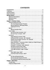
... The Main Menu ...3-2 Frequency/Voltage Control 3-3 v CONTENTS Copyright Notice ...iii Trademarks ...iii Technical Support ...iii Safety Instructions ...v Getting Started ...2-1 Mainboard Specifications 2-2 Mainboard Layout 2-4 Back Panel ...2-7 Chapter 2. Hardware Setup 2-1 Central Processing Unit: CPU 2-2 CPU Core Speed Derivation Procedure 2-3 Memory Speed/CPU FSB Support Matrix 2-3 Installing the CPU Fan 2-4 Memory ...2-5 Memory Population Rules 2-5 Power Supply ...2-6 ATX 20-Pin Power Connector: ATX1 2-6 ATX 12V Power Connector: JPW1 2-6 Connectors ...2-7 Floppy Disk Drive...
... The Main Menu ...3-2 Frequency/Voltage Control 3-3 v CONTENTS Copyright Notice ...iii Trademarks ...iii Technical Support ...iii Safety Instructions ...v Getting Started ...2-1 Mainboard Specifications 2-2 Mainboard Layout 2-4 Back Panel ...2-7 Chapter 2. Hardware Setup 2-1 Central Processing Unit: CPU 2-2 CPU Core Speed Derivation Procedure 2-3 Memory Speed/CPU FSB Support Matrix 2-3 Installing the CPU Fan 2-4 Memory ...2-5 Memory Population Rules 2-5 Power Supply ...2-6 ATX 20-Pin Power Connector: ATX1 2-6 ATX 12V Power Connector: JPW1 2-6 Connectors ...2-7 Floppy Disk Drive...

User Guide
Page 7
... Neo-V Main Memory h Supports six memory banks using three 184-pin DDR DIMMs h Supports dual-channel memory h Supports a maximum memory size up to 3GB h Supports 2.5v DDR SDRAM DIMM PT8 Neo-V/PX8 Neo-V Main Memory h Supports four memory banks using two 184-pin DDR DIMMs h Supports single-channel memory h Supports a maximum memory size up to 3.4GHz or higher speed (Please refer to 2GB h Supports 2.5v DDR SDRAM DIMM Slots h One AGP (Accelerated Graphics Port) slot supports 8x/4x (AGP 3.0) at http://www.msi.com.tw/program/products/mainboard/mbd...
... Neo-V Main Memory h Supports six memory banks using three 184-pin DDR DIMMs h Supports dual-channel memory h Supports a maximum memory size up to 3GB h Supports 2.5v DDR SDRAM DIMM PT8 Neo-V/PX8 Neo-V Main Memory h Supports four memory banks using two 184-pin DDR DIMMs h Supports single-channel memory h Supports a maximum memory size up to 3.4GHz or higher speed (Please refer to 2GB h Supports 2.5v DDR SDRAM DIMM Slots h One AGP (Accelerated Graphics Port) slot supports 8x/4x (AGP 3.0) at http://www.msi.com.tw/program/products/mainboard/mbd...

User Guide
Page 8
... mainboard specifications Dimension h ATX Form Factor: 30.5cm x 19.5cm Mounting h 6 standard mounting holes 1-3 Can connect up to four Ultra ATA drives Onboard Serial ATA (for PT880 Neo-V/PT8 Neo-V) h Serial ATA/150 controller integrated in VT8237 h VIA® VT1617 6-channel audio codec - Controlled by VT8237 southbridge - 4 ports in the VIA® VT8237 chipset - Supports IDE HDD/CD-ROM with PIO, Bus Master and Ultra DMA 66/100/133 operation modes - Getting Started Onboard IDE...
... mainboard specifications Dimension h ATX Form Factor: 30.5cm x 19.5cm Mounting h 6 standard mounting holes 1-3 Can connect up to four Ultra ATA drives Onboard Serial ATA (for PT880 Neo-V/PT8 Neo-V) h Serial ATA/150 controller integrated in VT8237 h VIA® VT1617 6-channel audio codec - Controlled by VT8237 southbridge - 4 ports in the VIA® VT8237 chipset - Supports IDE HDD/CD-ROM with PIO, Bus Master and Ultra DMA 66/100/133 operation modes - Getting Started Onboard IDE...
User Guide
Page 12
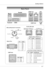
... Getting Started Back Panel Parallel SPDIF Out L-In (Optional) LAN Keyboard COMA Mouse/Keyboard Connector Pin6 NC Pin5 Mouse/KBD Clock USB Ports L-Out MIC RJ-45 LAN Jack Gigabit LAN (for PT880 Neo-V) 10/100Mbps LAN Activity Indicator Link Indicator Link Indicator Activity Indicator Pin4 VCC Pin3 GND Pin2 NC Pin1 Mouse/KBD DATA Serial Port 1 2 3 4 5 6 7 8 9 USB Ports PIN SIGNAL 1 DCD 2 SIN 3 SOUT 4 DTR 5 GND 6 DSR 7 RTS 8 CTS 9 RI 1 2 3 4 PIN...
... Getting Started Back Panel Parallel SPDIF Out L-In (Optional) LAN Keyboard COMA Mouse/Keyboard Connector Pin6 NC Pin5 Mouse/KBD Clock USB Ports L-Out MIC RJ-45 LAN Jack Gigabit LAN (for PT880 Neo-V) 10/100Mbps LAN Activity Indicator Link Indicator Link Indicator Activity Indicator Pin4 VCC Pin3 GND Pin2 NC Pin1 Mouse/KBD DATA Serial Port 1 2 3 4 5 6 7 8 9 USB Ports PIN SIGNAL 1 DCD 2 SIN 3 SOUT 4 DTR 5 GND 6 DSR 7 RTS 8 CTS 9 RI 1 2 3 4 PIN...
User Guide
Page 14
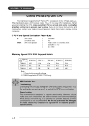
... attempt to prevent overheating. CPU Core Speed Derivation Procedure If then CPU Clock Core/Bus ratio CPU core speed = 200MHz = 12 = Host Clock x Core/Bus ratio = 200MHz x 12 = 2.4 GHz Memory Speed/CPU FSB Support Matrix Memory FSB DDR266 FSB400 OK DDR333 N/A DDR400 N/A FSB533 OK OK N/A FSB800 OK OK OK Note: 1. *: Overclocking specifications 2. However, please make sure the cooling fan can work properly to tolerate such abnormal settings while doing overclocking. When you do not...
... attempt to prevent overheating. CPU Core Speed Derivation Procedure If then CPU Clock Core/Bus ratio CPU core speed = 200MHz = 12 = Host Clock x Core/Bus ratio = 200MHz x 12 = 2.4 GHz Memory Speed/CPU FSB Support Matrix Memory FSB DDR266 FSB400 OK DDR333 N/A DDR400 N/A FSB533 OK OK N/A FSB800 OK OK OK Note: 1. *: Overclocking specifications 2. However, please make sure the cooling fan can work properly to tolerate such abnormal settings while doing overclocking. When you do not...
User Guide
Page 16
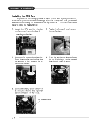
...-7043 ATX Mainboard Installing the CPU Fan As processor technology pushes to install the Heatsink/Fan: 1. To dissipate heat, you need to attach the CPU cooling fan and heatsink on the board. fan power cable 2-4 Follow the instructions below to faster speeds and higher performance, thermal management becomes increasingly important. Connect the fan power cable from the mounted fan to fasten the fan. Each lever can be pressed down to the 3-pin fan power connector on top of the heatsink.
...-7043 ATX Mainboard Installing the CPU Fan As processor technology pushes to install the Heatsink/Fan: 1. To dissipate heat, you need to attach the CPU cooling fan and heatsink on the board. fan power cable 2-4 Follow the instructions below to faster speeds and higher performance, thermal management becomes increasingly important. Connect the fan power cable from the mounted fan to fasten the fan. Each lever can be pressed down to the 3-pin fan power connector on top of the heatsink.

User Guide
Page 17
... S (for PT880 only) S: Single-Channel Mode D: Dual-Channel Mode Please refer to http://www.msi.com.tw/program/products/mainboard/ mbd/pro_mbd_trp_list.php for 184-pin, 2.5V DDR DIMM and supports up to 3GB memory size. Users may install memory modules of the same type and density on the slots. Under dual-channel mode, however, please make sure that DDR433/DDR466 are overclocking specs for PT880 Neo-V/PT8 Neo-V only. or double-sided...
... S (for PT880 only) S: Single-Channel Mode D: Dual-Channel Mode Please refer to http://www.msi.com.tw/program/products/mainboard/ mbd/pro_mbd_trp_list.php for 184-pin, 2.5V DDR DIMM and supports up to 3GB memory size. Users may install memory modules of the same type and density on the slots. Under dual-channel mode, however, please make sure that DDR433/DDR466 are overclocking specs for PT880 Neo-V/PT8 Neo-V only. or double-sided...
User Guide
Page 18
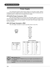
... power supplies. 2-6 Before inserting the power supply connector, always make sure the plug of 300watt (and up) are aligned. Power supplies of the power supply is used to provide power to ensure that no damage will be caused. Please refer to an ATX power supply. ATX 12V Power Connector: JPW1 This 12V power connector is inserted in the proper orientation and the pins are highly recommended for the power system. MS-7043 ATX Mainboard Power Supply The mainboard supports ATX power supply...
... power supplies. 2-6 Before inserting the power supply connector, always make sure the plug of 300watt (and up) are aligned. Power supplies of the power supply is used to provide power to ensure that no damage will be caused. Please refer to an ATX power supply. ATX 12V Power Connector: JPW1 This 12V power connector is inserted in the proper orientation and the pins are highly recommended for the power system. MS-7043 ATX Mainboard Power Supply The mainboard supports ATX power supply...
User Guide
Page 19
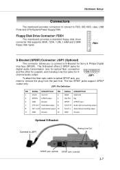
..., IDE HDD, case, USB Ports and CPU/System/Power Supply FAN. The S-Bracket offers 2 SPDIF jacks for digital audio transmission (one for optical fiber connection 2 12 and the other for coaxial), and 2 analog Line-Out jacks for Sony & Philips Digital Interface (SPDIF). The two SPDIF jacks support SPDIF output only. FDD1 S-Bracket (SPDIF) Connector: JSP1 (Optional) The connector allows you need to connect a S-Bracket for 4- 1 11 channel audio output. Hardware Setup Connectors The mainboard provides connectors to connect...
..., IDE HDD, case, USB Ports and CPU/System/Power Supply FAN. The S-Bracket offers 2 SPDIF jacks for digital audio transmission (one for optical fiber connection 2 12 and the other for coaxial), and 2 analog Line-Out jacks for Sony & Philips Digital Interface (SPDIF). The two SPDIF jacks support SPDIF output only. FDD1 S-Bracket (SPDIF) Connector: JSP1 (Optional) The connector allows you need to connect a S-Bracket for 4- 1 11 channel audio output. Hardware Setup Connectors The mainboard provides connectors to connect...
User Guide
Page 20
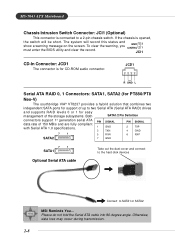
.../PT8 Neo-V) The southbridge VIA® VT8237 provides a hybrid solution that combines two independent SATA ports for support of 150 MB/s and are fully compliant with Serial ATA 1.0 specifications. 1 GND 3 TXN 7 1 5 RXN PIN SIGNAL 2 TXP 4 GND 6 RXP SATA2 7 GND 7 1 SATA1 Optional Serial ATA cable Take out the dust cover and connect to the hard disk devices Connect to a 2-pin chassis switch. MS-7043 ATX Mainboard Chassis Intrusion Switch Connector: JCI1 (Optional) This connector is connected to...
.../PT8 Neo-V) The southbridge VIA® VT8237 provides a hybrid solution that combines two independent SATA ports for support of 150 MB/s and are fully compliant with Serial ATA 1.0 specifications. 1 GND 3 TXN 7 1 5 RXN PIN SIGNAL 2 TXP 4 GND 6 RXP SATA2 7 GND 7 1 SATA1 Optional Serial ATA cable Take out the dust cover and connect to the hard disk devices Connect to a 2-pin chassis switch. MS-7043 ATX Mainboard Chassis Intrusion Switch Connector: JCI1 (Optional) This connector is connected to...

User Guide
Page 21
... Pin Definition Pin Signal combinations of the CPU fan control. It integrates four LEDs and allows users to GND. Always consult the vendors for you must use a specially designed fan with speed sensor to take note that supports both USB1.1 & 2.0 spec. If the mainboard has a System Hardware Monitor chipset onboard, you to connect to JUSB1/JUSB2 LEDs 2-9 D-Bracket™ 2 Connector: JDB1 (Optional) The mainboard comes with +12V. Hardware Setup Fan Power Connector: CPUFA1 The CPUFA1 (processor fan) supports...
... Pin Definition Pin Signal combinations of the CPU fan control. It integrates four LEDs and allows users to GND. Always consult the vendors for you must use a specially designed fan with speed sensor to take note that supports both USB1.1 & 2.0 spec. If the mainboard has a System Hardware Monitor chipset onboard, you to connect to JUSB1/JUSB2 LEDs 2-9 D-Bracket™ 2 Connector: JDB1 (Optional) The mainboard comes with +12V. Hardware Setup Fan Power Connector: CPUFA1 The CPUFA1 (processor fan) supports...
User Guide
Page 22
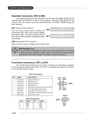
...; Front Panel I/ O Connectivity Design Guide. Do not use. IDE1 (Primary IDE Connector) The first hard drive should always be connected to GND Reserved. JFP2 Pin Definition PIN SIGNAL PIN SIGNAL 1 GND 2 SPK- 3 SLED 4 BUZ+ 5 PLED 6 BUZ- 7 NC 8 SPK+ 2-10 Power Power LED Switch 2 1 10 9 JFP1 HDD Reset LED Switch Speaker JFP2 2 1 8 7 Power LED MS-7043 ATX Mainboard Hard Disk Connectors: IDE1 & IDE2 The mainboard has a 32-bit Enhanced PCI IDE and Ultra DMA 33/66/100/133 controller that provides PIO mode 0~4, Bus Master, and...
...; Front Panel I/ O Connectivity Design Guide. Do not use. IDE1 (Primary IDE Connector) The first hard drive should always be connected to GND Reserved. JFP2 Pin Definition PIN SIGNAL PIN SIGNAL 1 GND 2 SPK- 3 SLED 4 BUZ+ 5 PLED 6 BUZ- 7 NC 8 SPK+ 2-10 Power Power LED Switch 2 1 10 9 JFP1 HDD Reset LED Switch Speaker JFP2 2 1 8 7 Power LED MS-7043 ATX Mainboard Hard Disk Connectors: IDE1 & IDE2 The mainboard has a 32-bit Enhanced PCI IDE and Ultra DMA 33/66/100/133 controller that provides PIO mode 0~4, Bus Master, and...
User Guide
Page 24
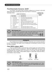
... is turned on the back panel will damage the mainboard. 2-12 If you don't want to the rear audio ports. Otherwise, the Line-Out 6 10 connector on . If you want to connect to the front audio header, pins 5 & 6, 9 & 10 have to be jumpered in order to have signal output directed to clear the system configuration, use of system configuration. Clear CMOS Jumper: JBAT1 There is on board that has a power supply...
... is turned on the back panel will damage the mainboard. 2-12 If you don't want to the rear audio ports. Otherwise, the Line-Out 6 10 connector on . If you want to connect to the front audio header, pins 5 & 6, 9 & 10 have to be jumpered in order to have signal output directed to clear the system configuration, use of system configuration. Clear CMOS Jumper: JBAT1 There is on board that has a power supply...

User Guide
Page 25
... software settings for the graphics controller to directly access main memory. PCI Slot PCI Interrupt Request Routing The IRQ, acronym of 3D graphics. AGP is an interface specification designed for the throughput demands of interrupt request line and pronounced I-R-Q, are typically connected to the microprocessor. The PCI IRQ pins are hardware lines over which devices can send interrupt signals to the PCI bus INT A# ~ INT D# pins as jumpers, switches or BIOS configuration. The slot supports...
... software settings for the graphics controller to directly access main memory. PCI Slot PCI Interrupt Request Routing The IRQ, acronym of 3D graphics. AGP is an interface specification designed for the throughput demands of interrupt request line and pronounced I-R-Q, are typically connected to the microprocessor. The PCI IRQ pins are hardware lines over which devices can send interrupt signals to the PCI bus INT A# ~ INT D# pins as jumpers, switches or BIOS configuration. The slot supports...

User Guide
Page 26
... the model number. 6th - 7th digit refers to change the default settings for optimum use. V1.0 refers to the BIOS version. 091096 refers to our website at: http://www.msi.com.tw. 3-1 Upon boot-up , and requests you to run the Setup program when: — An error message appears on the screen during the system boot- BIOS Setup BIOS Setup This chapter provides Frequency/Voltage Control information on the BIOS Setup program...
... the model number. 6th - 7th digit refers to change the default settings for optimum use. V1.0 refers to the BIOS version. 091096 refers to our website at: http://www.msi.com.tw. 3-1 Upon boot-up , and requests you to run the Setup program when: — An error message appears on the screen during the system boot- BIOS Setup BIOS Setup This chapter provides Frequency/Voltage Control information on the BIOS Setup program...

User Guide
Page 27
... your system supports PnP/PCI. Power Management Features Use this menu to load the BIOS values for power management. Load High Performance Defaults Use this menu to specify your settings for frequency/voltage control. Load Optimal Defaults Use this menu to setup the items of AMI® special enhanced features. Advanced Chipset Features Use this menu to load the factory default settings for basic system configurations, such as time, date etc. MS-7043 ATX Mainboard The Main Menu Standard CMOS Features Use this menu for optimal...
... your system supports PnP/PCI. Power Management Features Use this menu to load the BIOS values for power management. Load High Performance Defaults Use this menu to specify your settings for frequency/voltage control. Load Optimal Defaults Use this menu to setup the items of AMI® special enhanced features. Advanced Chipset Features Use this menu to load the factory default settings for basic system configurations, such as time, date etc. MS-7043 ATX Mainboard The Main Menu Standard CMOS Features Use this menu for optimal...

User Guide
Page 28
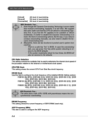
... EMI, set to [Enabled] for optimal system stability and performance. Remember to disable Spread Spectrum if you are overclocking because even a slight jitter can introduce a temporary boost in the low load balance, it will speed up to enhance the overall performance. When the CPU is designed to adjust the best CPU frequency automatically. BIOS Setup Frequency/Voltage Control Spread Spectrum When the motherboard's clock generator pulses...
... EMI, set to [Enabled] for optimal system stability and performance. Remember to disable Spread Spectrum if you are overclocking because even a slight jitter can introduce a temporary boost in the low load balance, it will speed up to enhance the overall performance. When the CPU is designed to adjust the best CPU frequency automatically. BIOS Setup Frequency/Voltage Control Spread Spectrum When the motherboard's clock generator pulses...
User Guide
Page 29
... the Dynamic Overclocking Technology is used to determine the internal clock speed of the processor relative to the defaults. MSI Reminds You... 1. If you find the PC appears to be restored to the external or motherboard clock speed. CPU FSB Clock This setting shows the current CPU Front Side Bus clock frequency. Meanwhile, there are two functions to configure the clock frequency of overclocking options. In case the overclocking fails, you also need to conduct overclocking manually, you...
... the Dynamic Overclocking Technology is used to determine the internal clock speed of the processor relative to the defaults. MSI Reminds You... 1. If you find the PC appears to be restored to the external or motherboard clock speed. CPU FSB Clock This setting shows the current CPU Front Side Bus clock frequency. Meanwhile, there are two functions to configure the clock frequency of overclocking options. In case the overclocking fails, you also need to conduct overclocking manually, you...

