User Guide
Page 2
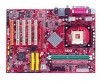
Notice 2 Shielded interface cables and A.C. ii power cord, if any interference received, including interference that may cause harmful interference to radio communications. Manual Rev: 1.0 Release Date: March 2004 FCC-A Radio Frequency Interference Statement This equipment has been tested and found to comply with the limits for compliance could void the user's authority to part 15 of the FCC Rules. These limits are designed to provide reasonable protection against harmful interference when the equipment is subject to the following two conditions: (1) this device may not ...
Notice 2 Shielded interface cables and A.C. ii power cord, if any interference received, including interference that may cause harmful interference to radio communications. Manual Rev: 1.0 Release Date: March 2004 FCC-A Radio Frequency Interference Statement This equipment has been tested and found to comply with the limits for compliance could void the user's authority to part 15 of the FCC Rules. These limits are designed to provide reasonable protection against harmful interference when the equipment is subject to the following two conditions: (1) this device may not ...

User Guide
Page 3
...help resources for FAQ, technical guide, BIOS updates, driver updates, and other information: http://www.msi.com.tw/program/service/faq/faq/esc_faq_list.php Contact our technical staff at: support@msi.com.tw iii We take every care in this document, but no solution can be obtained ...Date March 2004 Technical Support If a problem arises with your system and no guarantee is given as to make changes without notice. Visit the MSI website for further guidance. Our products are under continual improvement and we reserve the right to the correctness of its contents. Netware® is...
...help resources for FAQ, technical guide, BIOS updates, driver updates, and other information: http://www.msi.com.tw/program/service/faq/faq/esc_faq_list.php Contact our technical staff at: support@msi.com.tw iii We take every care in this document, but no solution can be obtained ...Date March 2004 Technical Support If a problem arises with your system and no guarantee is given as to make changes without notice. Visit the MSI website for further guidance. Our products are under continual improvement and we reserve the right to the correctness of its contents. Netware® is...

User Guide
Page 4
CAUTION: Danger of the power source and adjust properly 110/220V before setting it . Always read the safety instructions carefully. 2. Keep this equipment away from overheating. Lay this equipment on a reliable flat surface before connecting the equipment to the power inlet. 7. ment from humidity. 4. Make sure the voltage of explosion if battery is damaged. †† Liquid has penetrated into the opening that people can not get the equipment checked by the manufacturer. Never pour any liquid into the equipment. †† The equipment has been exposed ...
CAUTION: Danger of the power source and adjust properly 110/220V before setting it . Always read the safety instructions carefully. 2. Keep this equipment away from overheating. Lay this equipment on a reliable flat surface before connecting the equipment to the power inlet. 7. ment from humidity. 4. Make sure the voltage of explosion if battery is damaged. †† Liquid has penetrated into the opening that people can not get the equipment checked by the manufacturer. Never pour any liquid into the equipment. †† The equipment has been exposed ...
User Guide
Page 5
... Speed/CPU FSB Support Matrix 2-3 Installing the CPU Fan 2-4 Memory ...2-5 Memory Population Rules 2-5 Power Supply ...2-6 ATX 20-Pin Power Connector: ATX1 2-6 ATX 12V Power Connector: JPW1 2-6 Connectors ...2-7 Floppy Disk Drive Connector: FDD1 2-7 S-Bracket (SPDIF) Connector: JSP1 ...(Optional 2-7 Chassis Intrusion Switch Connector: JCI1 (Optional 2-8 CD-In Connector: JCD1 2-8 Serial ATA RAID 0, 1 Connectors: SATA1, SATA2 (for PT880/PT8 Neo-V) 2-8 ...
... Speed/CPU FSB Support Matrix 2-3 Installing the CPU Fan 2-4 Memory ...2-5 Memory Population Rules 2-5 Power Supply ...2-6 ATX 20-Pin Power Connector: ATX1 2-6 ATX 12V Power Connector: JPW1 2-6 Connectors ...2-7 Floppy Disk Drive Connector: FDD1 2-7 S-Bracket (SPDIF) Connector: JSP1 ...(Optional 2-7 Chassis Intrusion Switch Connector: JCI1 (Optional 2-8 CD-In Connector: JCD1 2-8 Serial ATA RAID 0, 1 Connectors: SATA1, SATA2 (for PT880/PT8 Neo-V) 2-8 ...

User Guide
Page 6
The MS-7043 series are superior computer mainboards based on VIA® PT880/PT800/P4X533 Northbridge & VT8237 Southbridge for choosing the MS-7043 (PT880 Neo-V/PT8 NeoV/PX8 Neo-V) v1.X ATX mainboards. Designed to fit the advanced Intel® Pentium® 4 processors in 478 pin package, the MS-7043 series deliver a high performance and professional desktop platform solution. 1-1 Getting Started Getting Started Thank you for optimal system efficiency.
The MS-7043 series are superior computer mainboards based on VIA® PT880/PT800/P4X533 Northbridge & VT8237 Southbridge for choosing the MS-7043 (PT880 Neo-V/PT8 NeoV/PX8 Neo-V) v1.X ATX mainboards. Designed to fit the advanced Intel® Pentium® 4 processors in 478 pin package, the MS-7043 series deliver a high performance and professional desktop platform solution. 1-1 Getting Started Getting Started Thank you for optimal system efficiency.

User Guide
Page 7
...184-pin DDR DIMMs h Supports dual-channel memory h Supports a maximum memory size up to 3GB h Supports 2.5v DDR SDRAM DIMM PT8 Neo-V/PX8 Neo-V Main Memory h Supports four memory banks using two 184-pin DDR DIMMs h Supports single-channel memory h Supports a maximum memory size up... slot supports 8x/4x (AGP 3.0) at http://www.msi.com.tw/program/products/mainboard/mbd/ pro_mbd_cpu_support.php) Chipset h VIA® PT880 chipset (for PT880 Neo-V) - Supports AGP 8X interface - High Bandwidth V-link Client controller - MS-7043 ATX Mainboard Mainboard Specifications CPU h Supports Intel® P4 ...
...184-pin DDR DIMMs h Supports dual-channel memory h Supports a maximum memory size up to 3GB h Supports 2.5v DDR SDRAM DIMM PT8 Neo-V/PX8 Neo-V Main Memory h Supports four memory banks using two 184-pin DDR DIMMs h Supports single-channel memory h Supports a maximum memory size up... slot supports 8x/4x (AGP 3.0) at http://www.msi.com.tw/program/products/mainboard/mbd/ pro_mbd_cpu_support.php) Chipset h VIA® PT880 chipset (for PT880 Neo-V) - Supports AGP 8X interface - High Bandwidth V-link Client controller - MS-7043 ATX Mainboard Mainboard Specifications CPU h Supports Intel® P4 ...

User Guide
Page 8
...the VIA® VT8237 chipset - Meets PC2001 audio performance requirement PT880 Neo-V LAN h VIA® VT8237 integrated MAC h VIA® VT6122 Gigabit LAN controller PT8 Neo-V/PX8 Neo-V LAN h VIA® VT8237 integrated MAC h VIA® VT6103L... 10/100 PHY BIOS h The mainboard BIOS provides "Plug & Play" BIOS which detects the peripheral devices and expansion cards of the board automatically h The mainboard provides a Desktop Management Interface (DMI) function which records your mainboard specifications Dimension h ATX...
...the VIA® VT8237 chipset - Meets PC2001 audio performance requirement PT880 Neo-V LAN h VIA® VT8237 integrated MAC h VIA® VT6122 Gigabit LAN controller PT8 Neo-V/PX8 Neo-V LAN h VIA® VT8237 integrated MAC h VIA® VT6103L... 10/100 PHY BIOS h The mainboard BIOS provides "Plug & Play" BIOS which detects the peripheral devices and expansion cards of the board automatically h The mainboard provides a Desktop Management Interface (DMI) function which records your mainboard specifications Dimension h ATX...
User Guide
Page 12
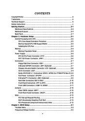
... 5 GND 6 DSR 7 RTS 8 CTS 9 RI 1 2 3 4 PIN SIGNAL 1 VCC 2 -Data 3 +Data 4 GND 8 1 8 1 Gigabit LAN (for PT880 Neo-V) PIN SIGNAL DESCRIPTION 1 D0P Differential Pair 0+ 2 D0N 3 D1P Differential Pair 0Differential Pair 1+ 4 D2P 5 D2N Differential Pair 2+ Differential Pair 2- 6 D1N 7 D3P Differential Pair... 1Differential Pair 3+ 8 D3N Differential Pair 3- 10/100 LAN (for PT8 Neo-V/PX8 Neo-V) PIN SIGNAL DESCRIPTION 1 TDP Transmit Differential Pair 2 TDN Transmit Differential Pair 3 RDP Receive Differential Pair 4 NC...
... 5 GND 6 DSR 7 RTS 8 CTS 9 RI 1 2 3 4 PIN SIGNAL 1 VCC 2 -Data 3 +Data 4 GND 8 1 8 1 Gigabit LAN (for PT880 Neo-V) PIN SIGNAL DESCRIPTION 1 D0P Differential Pair 0+ 2 D0N 3 D1P Differential Pair 0Differential Pair 1+ 4 D2P 5 D2N Differential Pair 2+ Differential Pair 2- 6 D1N 7 D3P Differential Pair... 1Differential Pair 3+ 8 D3N Differential Pair 3- 10/100 LAN (for PT8 Neo-V/PX8 Neo-V) PIN SIGNAL DESCRIPTION 1 TDP Transmit Differential Pair 2 TDN Transmit Differential Pair 3 RDP Receive Differential Pair 4 NC...

User Guide
Page 13
Hardware Setup Hardware Setup This chapter provides you install in holding the components and follow the installation procedures. For some components, if you with the information about hardware setup procedures. Static electricity may damage the components. 2-1 Use a grounded wrist strap before handling computer components. While doing the installation, be careful in the wrong orientation, the components will not work properly. Hardware Setup Chapter 2.
Hardware Setup Hardware Setup This chapter provides you install in holding the components and follow the installation procedures. For some components, if you with the information about hardware setup procedures. Static electricity may damage the components. 2-1 Use a grounded wrist strap before handling computer components. While doing the installation, be careful in the wrong orientation, the components will not work properly. Hardware Setup Chapter 2.
User Guide
Page 14
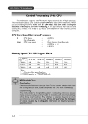
...PT880/PT800 only DDR433 N/A N/A OK* DDR466 N/A N/A OK* MSI Reminds You... Overheating Overheating will seriously damage the CPU and system,..., make sure the CPU has a heat sink and a cooling fan attached on the computer. Overclocking This motherboard is not recommended. CPU Core Speed Derivation Procedure If then CPU Clock Core/Bus ratio CPU core speed =...or risks caused by inadequate operation or beyond product specifications is designed to support overclocking. MS-7043 ATX Mainboard Central Processing Unit: CPU The mainboard supports Intel® Pentium® 4 processors in the...
...PT880/PT800 only DDR433 N/A N/A OK* DDR466 N/A N/A OK* MSI Reminds You... Overheating Overheating will seriously damage the CPU and system,..., make sure the CPU has a heat sink and a cooling fan attached on the computer. Overclocking This motherboard is not recommended. CPU Core Speed Derivation Procedure If then CPU Clock Core/Bus ratio CPU core speed =...or risks caused by inadequate operation or beyond product specifications is designed to support overclocking. MS-7043 ATX Mainboard Central Processing Unit: CPU The mainboard supports Intel® Pentium® 4 processors in the...
User Guide
Page 15
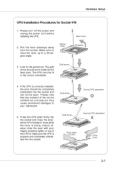
Make sure to raise the lever up to move while the lever is correctly installed, the pins should point towards the lever pivot. The CPU can not be seen. Please note that any violation of the CPU to your mainboard. Gold arrow Press down firmly into the socket and close the lever with your fingers pressing tightly on top of the correct installation procedures may cause permanent damages to make sure the CPU is properly and completely embedded into the socket and can only fit in the correct orientation. Hardware Setup CPU Installation Procedures for the gold arrow. Please turn off ...
Make sure to raise the lever up to move while the lever is correctly installed, the pins should point towards the lever pivot. The CPU can not be seen. Please note that any violation of the CPU to your mainboard. Gold arrow Press down firmly into the socket and close the lever with your fingers pressing tightly on top of the correct installation procedures may cause permanent damages to make sure the CPU is properly and completely embedded into the socket and can only fit in the correct orientation. Hardware Setup CPU Installation Procedures for the gold arrow. Please turn off ...
User Guide
Page 16
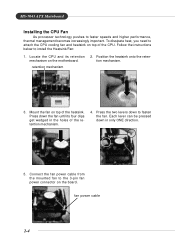
.... Each lever can be pressed down the fan until its retention mechanism on top of the retention mechanism. 4. retention mechanism 2. Mount the fan on the motherboard. MS-7043 ATX Mainboard Installing the CPU Fan As processor technology pushes to the 3-pin fan power connector on top of the CPU.
.... Each lever can be pressed down the fan until its retention mechanism on top of the retention mechanism. 4. retention mechanism 2. Mount the fan on the motherboard. MS-7043 ATX Mainboard Installing the CPU Fan As processor technology pushes to the 3-pin fan power connector on top of the CPU.

User Guide
Page 17
...msi.com.tw/program/products/mainboard/ mbd/pro_mbd_trp_list.php for PT880 Neo-V/PT8 Neo-V only. Memory modules can install DDR266 / DDR333 / DDR400 (for PT8 Neo-V only) / DDR433 (for PT8 Neo-V only)/DDR466 (for 184-pin, 2.5V DDR DIMM and supports up to ensure system stability. Users may install memory modules of 1GB. The PT8 Neo-V & PX8 Neo...-V provide 2 slots for PT880 only) Memory Population Rules Install at least one DIMM module on the slots. The PT880 Neo-V supports dual-channel mode and the PT8 Neo-V & PX8 NeoV support only single-channel...
...msi.com.tw/program/products/mainboard/ mbd/pro_mbd_trp_list.php for PT880 Neo-V/PT8 Neo-V only. Memory modules can install DDR266 / DDR333 / DDR400 (for PT8 Neo-V only) / DDR433 (for PT8 Neo-V only)/DDR466 (for 184-pin, 2.5V DDR DIMM and supports up to ensure system stability. Users may install memory modules of 1GB. The PT8 Neo-V & PX8 Neo...-V provide 2 slots for PT880 only) Memory Population Rules Install at least one DIMM module on the slots. The PT880 Neo-V supports dual-channel mode and the PT8 Neo-V & PX8 NeoV support only single-channel...
User Guide
Page 18
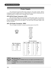
... 9 5V_SB 10 12V PIN SIGNAL 11 3.3V 12 -12V 13 GND 14 PS_ON 15 GND 16 GND 17 GND 18 -5V 19 5V 20 5V MSI Reminds You... 1. Power supplies of the power supply is used to provide power to ensure that no damage will be caused. Please refer to an... ATX power supply. Then push down the power supply firmly into the connector. ATX 12V Power Connector: JPW1 This 12V power connector is inserted in the proper orientation and the pins are highly...
... 9 5V_SB 10 12V PIN SIGNAL 11 3.3V 12 -12V 13 GND 14 PS_ON 15 GND 16 GND 17 GND 18 -5V 19 5V 20 5V MSI Reminds You... 1. Power supplies of the power supply is used to provide power to ensure that no damage will be caused. Please refer to an... ATX power supply. Then push down the power supply firmly into the connector. ATX 12V Power Connector: JPW1 This 12V power connector is inserted in the proper orientation and the pins are highly...
User Guide
Page 19
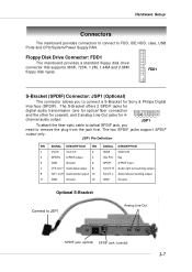
JSP1 Pin Definition PIN SIGNAL DESCRIPTION PIN SIGNAL DESCRIPTION 1 VCC5 VCC 5V 2 VDD3 VDD 3.3V 3 SPDFO S/PDIF output 4 (No Pin) Key 5 GND Ground 6 SPDFI S/PDIF input 7 LFE-OUT Audio bass output 8 SOUT-R Audio right surrounding output 9 CET-OUT Audio center output 10 SOUT-L Audio left surrounding output 11 GND Ground 12 GND Ground Optional S-Bracket Connect to FDD, IDE HDD, case, USB Ports and CPU/System/Power Supply FAN. The two SPDIF jacks support SPDIF output only. The S-Bracket offers 2 SPDIF jacks for digital audio transmission (one for optical ...
JSP1 Pin Definition PIN SIGNAL DESCRIPTION PIN SIGNAL DESCRIPTION 1 VCC5 VCC 5V 2 VDD3 VDD 3.3V 3 SPDFO S/PDIF output 4 (No Pin) Key 5 GND Ground 6 SPDFI S/PDIF input 7 LFE-OUT Audio bass output 8 SOUT-R Audio right surrounding output 9 CET-OUT Audio center output 10 SOUT-L Audio left surrounding output 11 GND Ground 12 GND Ground Optional S-Bracket Connect to FDD, IDE HDD, case, USB Ports and CPU/System/Power Supply FAN. The two SPDIF jacks support SPDIF output only. The S-Bracket offers 2 SPDIF jacks for digital audio transmission (one for optical ...
User Guide
Page 20
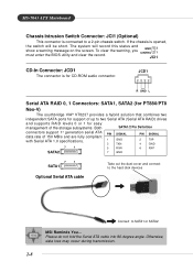
...Serial ATA cable into 90-degree angle. Otherwise, data loss may occur during transmission. 2-8 JCD1 R GND L Serial ATA RAID 0, 1 Connectors: SATA1, SATA2 (for PT880/PT8 Neo-V) The southbridge VIA® VT8237 provides a hybrid solution that combines two independent SATA ports for support of up to two Serial ATA (Serial ATA RAID...) drives and supports RAID levels 0 or 1 for CD-ROM audio connector. MS-7043 ATX Mainboard Chassis Intrusion Switch Connector: JCI1 (Optional) This connector is connected to SATA1 or SATA2...
...Serial ATA cable into 90-degree angle. Otherwise, data loss may occur during transmission. 2-8 JCD1 R GND L Serial ATA RAID 0, 1 Connectors: SATA1, SATA2 (for PT880/PT8 Neo-V) The southbridge VIA® VT8237 provides a hybrid solution that combines two independent SATA ports for support of up to two Serial ATA (Serial ATA RAID...) drives and supports RAID levels 0 or 1 for CD-ROM audio connector. MS-7043 ATX Mainboard Chassis Intrusion Switch Connector: JCI1 (Optional) This connector is connected to SATA1 or SATA2...

User Guide
Page 21
... and allows users to identify system problems through 16 various JDB1 Pin Definition Pin Signal combinations of the CPU fan control. GND +12V Sensor CPUFA1 MSI Reminds You... When connecting the wire to the connectors, always take advantage of LED signals. 1 DBG1 (high for green color) 2 DBR1 (high for red color...
... and allows users to identify system problems through 16 various JDB1 Pin Definition Pin Signal combinations of the CPU fan control. GND +12V Sensor CPUFA1 MSI Reminds You... When connecting the wire to the connectors, always take advantage of LED signals. 1 DBG1 (high for green color) 2 DBR1 (high for red color...
User Guide
Page 22
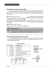
MSI Reminds You... Refer to the hard disk documentation supplied by hard disk vendors for electrical connection to GND Reserved. Do not use. You can connect ... 1 GND 2 SPK- 3 SLED 4 BUZ+ 5 PLED 6 BUZ- 7 NC 8 SPK+ 2-10 Power Power LED Switch 2 1 10 9 JFP1 HDD Reset LED Switch Speaker JFP2 2 1 8 7 Power LED MS-7043 ATX Mainboard Hard Disk Connectors: IDE1 & IDE2 The mainboard has a 32-bit Enhanced PCI IDE and Ultra DMA 33/66/100/133 controller that provides PIO...
MSI Reminds You... Refer to the hard disk documentation supplied by hard disk vendors for electrical connection to GND Reserved. Do not use. You can connect ... 1 GND 2 SPK- 3 SLED 4 BUZ+ 5 PLED 6 BUZ- 7 NC 8 SPK+ 2-10 Power Power LED Switch 2 1 10 9 JFP1 HDD Reset LED Switch Speaker JFP2 2 1 8 7 Power LED MS-7043 ATX Mainboard Hard Disk Connectors: IDE1 & IDE2 The mainboard has a 32-bit Enhanced PCI IDE and Ultra DMA 33/66/100/133 controller that provides PIO...
User Guide
Page 23
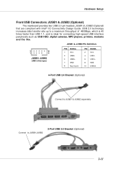
JUSB1 & JUSB2 Pin Definition 2 10 1 9 JUSB1/ JUSB2 (USB 2.0/Intel spec) PIN SIGNAL 1 VCC 3 USB0- 5 USB0+ 7 GND 9 Key (no pin) PIN SIGNAL 2 VCC 4 USB1- 6 USB1+ 8 GND 10 USBOC 4-Port USB 2.0 Bracket (Optional) Connect to JUSB1 & JUSB2 separately Connect to a maximum throughput of 480Mbps, which is 40 times faster than USB 1.1, and is ideal for connecting high-speed USB interface peripherals such as USB HDD, digital cameras, MP3 players, printers, modems and the like. Hardware Setup Front USB Connectors: JUSB1 & JUSB2 (Optional) The mainboard provides two USB 2.0...
JUSB1 & JUSB2 Pin Definition 2 10 1 9 JUSB1/ JUSB2 (USB 2.0/Intel spec) PIN SIGNAL 1 VCC 3 USB0- 5 USB0+ 7 GND 9 Key (no pin) PIN SIGNAL 2 VCC 4 USB1- 6 USB1+ 8 GND 10 USBOC 4-Port USB 2.0 Bracket (Optional) Connect to JUSB1 & JUSB2 separately Connect to a maximum throughput of 480Mbps, which is 40 times faster than USB 1.1, and is ideal for connecting high-speed USB interface peripherals such as USB HDD, digital cameras, MP3 players, printers, modems and the like. Hardware Setup Front USB Connectors: JUSB1 & JUSB2 (Optional) The mainboard provides two USB 2.0...
User Guide
Page 24
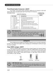
...to the front panel audio and is compliant with Intel® Front Panel I/O Connectiv- This section will damage the mainboard. 2-12 MS-7043 ATX Mainboard Front Panel Audio Connector: JAUD1 The JAUD1 front panel audio connector allows you want to connect to the front audio header, pins 5 &...to clear the data: 1 1 1 JBAT1 3 Keep Data 3 Clear Data MSI Reminds You... Clear CMOS Jumper: JBAT1 There is off. You can automatically boot OS every time it will explain how to change your motherboard's function through the use the JBAT1 (Clear CMOS Jumper ) to clear data. ...
...to the front panel audio and is compliant with Intel® Front Panel I/O Connectiv- This section will damage the mainboard. 2-12 MS-7043 ATX Mainboard Front Panel Audio Connector: JAUD1 The JAUD1 front panel audio connector allows you want to connect to the front audio header, pins 5 &...to clear the data: 1 1 1 JBAT1 3 Keep Data 3 Clear Data MSI Reminds You... Clear CMOS Jumper: JBAT1 There is off. You can automatically boot OS every time it will explain how to change your motherboard's function through the use the JBAT1 (Clear CMOS Jumper ) to clear data. ...