User Guide
Page 2
Our products are registered trademarks of NVIDIA Corporation in the United States and/or other information: http://global.msi.com.tw/index.php? NVIDIA, the NVIDIA logo, DualNet, and nForce are registered trademarks or trademarks of AMD Corporation. Netware... registered trademark of M ICRO-STAR INTERNATIONAL. Alternatively, please try the following help resources for FAQ, technical guide, BIOS updates, driver updates, and other countries. Visit the MSI website for further guidance. Copyright Notice The material in this document, but no solution can be obtained from the user...
Our products are registered trademarks of NVIDIA Corporation in the United States and/or other information: http://global.msi.com.tw/index.php? NVIDIA, the NVIDIA logo, DualNet, and nForce are registered trademarks or trademarks of AMD Corporation. Netware... registered trademark of M ICRO-STAR INTERNATIONAL. Alternatively, please try the following help resources for FAQ, technical guide, BIOS updates, driver updates, and other countries. Visit the MSI website for further guidance. Copyright Notice The material in this document, but no solution can be obtained from the user...
User Guide
Page 8
... v English ...En-1 Specifications ...En-2 Central Processing Unit: CPU En-5 Memory ...En-7 Connectors, Jumpers, Slots En-9 Back Panel ...En-18 BIOS Setup ...En-21 Software Information En-25 Deutsch ...De-1 Spezifikationen De-2 Hauptprozessor: CPU De-5 Speicher ...De-7 Anschlüsse, Steckbrücken... und Slots De-9 Hinteres Anschlusspaneel De-18 BIOS Setup ...De-21 Software-Information De-25 Français ...Fr-1 Spécificités ...Fr-2 Central Processing Unit: CPU Fr-5...
... v English ...En-1 Specifications ...En-2 Central Processing Unit: CPU En-5 Memory ...En-7 Connectors, Jumpers, Slots En-9 Back Panel ...En-18 BIOS Setup ...En-21 Software Information En-25 Deutsch ...De-1 Spezifikationen De-2 Hauptprozessor: CPU De-5 Speicher ...De-7 Anschlüsse, Steckbrücken... und Slots De-9 Hinteres Anschlusspaneel De-18 BIOS Setup ...De-21 Software-Information De-25 Français ...Fr-1 Spécificités ...Fr-2 Central Processing Unit: CPU Fr-5...
User Guide
Page 14
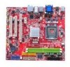
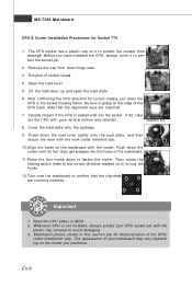
... the cooler. Remove the cap from damage. Note that the clip-ends are m atched. 7. Cover the load plate onto the package. 9. Mainboard photos shown in BIOS. 2. Be sure to grasp on it to protect the contact from lever hinge side. 3. The appearance of the mainboard. 11.Press the four hooks down...
... the cooler. Remove the cap from damage. Note that the clip-ends are m atched. 7. Cover the load plate onto the package. 9. Mainboard photos shown in BIOS. 2. Be sure to grasp on it to protect the contact from lever hinge side. 3. The appearance of the mainboard. 11.Press the four hooks down...

User Guide
Page 20
... on the screen. L GND R 15 Chassis Intrusion Connector This connector connects to the chassis intrusion switch cable. To clear the warning, you must enter the BIOS utility and clear the record. 1 CINTRU 2 GND En-12 The system will record this status and show a warning message on the back panel will be...
... on the screen. L GND R 15 Chassis Intrusion Connector This connector connects to the chassis intrusion switch cable. To clear the warning, you must enter the BIOS utility and clear the record. 1 CINTRU 2 GND En-12 The system will record this status and show a warning message on the back panel will be...

User Guide
Page 21
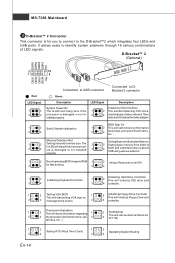
... Connector This connector allows you to attach an optional TV-Out bracket that sends/receives 16 bytes FIFOs. You must configure the setting through the BIOS setup to use the infrared function. 12 NC NC VCC5 Ground IRTX IRRX 56 17 Serial Port Connector This connector is compliant with Intel®...
... Connector This connector allows you to attach an optional TV-Out bracket that sends/receives 16 bytes FIFOs. You must configure the setting through the BIOS setup to use the infrared function. 12 NC NC VCC5 Ground IRTX IRRX 56 17 Serial Port Connector This connector is compliant with Intel®...
User Guide
Page 22
...Bracket™2 which integrates four LEDs and USB ports. Then, detect and initializethe video adapter. 1 2 EarlyChipset Initialization 3 4 BIOS Sign On 1 2 This will start writing VGA sign-on 4 message to the screen. 3 2 Processor Initialization This will ...Keyboard Controller. 1 2 Initializing Hard Drive Controller This will initialize IDE drive and 3 4 3 4 controller. 1 3 1 3 1 3 En-14 2 Testing VGA BIOS 1 This will start showing information 3 4 about logo, processor brand name, etc... 1 3 Memory Detection Test 2 Testing onboard memory size. MS-7366 Mainboard 20 ...
...Bracket™2 which integrates four LEDs and USB ports. Then, detect and initializethe video adapter. 1 2 EarlyChipset Initialization 3 4 BIOS Sign On 1 2 This will start writing VGA sign-on 4 message to the screen. 3 2 Processor Initialization This will ...Keyboard Controller. 1 2 Initializing Hard Drive Controller This will initialize IDE drive and 3 4 3 4 controller. 1 3 1 3 1 3 En-14 2 Testing VGA BIOS 1 This will start showing information 3 4 about logo, processor brand name, etc... 1 3 Memory Detection Test 2 Testing onboard memory size. MS-7366 Mainboard 20 ...

User Guide
Page 25
...). Meanwhile, read the documentation for the expansion card to configure any necessary hardware or software settings for the expansion card, such as jumpers, switches or BIOS configuration. 30 TPM Module Connector This connector connects to the TPM security platform manual for more details and usages.
...). Meanwhile, read the documentation for the expansion card to configure any necessary hardware or software settings for the expansion card, such as jumpers, switches or BIOS configuration. 30 TPM Module Connector This connector connects to the TPM security platform manual for more details and usages.

User Guide
Page 29
...vender as A = AMD, I = Intel, V = VIA, N = Nvidia, U = ULi. 7th - 8th digit refers to the customer as MS = all standard customers. It is the BIOS version. V1.0 refers to the BIOS version. 101007 refers to change the default settings for customized features. En-21 Therefore, the description may need to run...the screen during the system booting up , the 1st line appearing after the memory count is usually in this BIOS was released. You may be slightly different from the latest BIOS and should be held for reference only. 2.Upon boot-up , and requests you to configure the system ...
...vender as A = AMD, I = Intel, V = VIA, N = Nvidia, U = ULi. 7th - 8th digit refers to the customer as MS = all standard customers. It is the BIOS version. V1.0 refers to the BIOS version. 101007 refers to change the default settings for customized features. En-21 Therefore, the description may need to run...the screen during the system booting up , the 1st line appearing after the memory count is usually in this BIOS was released. You may be slightly different from the latest BIOS and should be held for reference only. 2.Upon boot-up , and requests you to configure the system ...

User Guide
Page 30
... system by turning it OFF and On or pressing the RESET button. Then you will start POST (Power On Self Test) process. General Help The BIOS setup program provides a General Help screen. The Help screen lists the appropriate keys to exit the Help screen. The on-line description of the highlighted...
... system by turning it OFF and On or pressing the RESET button. Then you will start POST (Power On Self Test) process. General Help The BIOS setup program provides a General Help screen. The Help screen lists the appropriate keys to exit the Help screen. The on-line description of the highlighted...

User Guide
Page 31
... Saving Abandon all changes and exit setup. The Main Menu allows you enter AMI® or AW ARD® BIOS CMOS Setup Utility, the Main Menu will appear on the screen. BIOS Setting Password Use this menu to select from ten setup functions and two exit choices. Standard CMOS Features Use this... for fequency/voltage control and overclocking. PNP/PCI Configurations This entry appears if your PC health status. Advanced BIOS Features Use this menu for optim al perform ance of special enhanced features. Use arrow keys to select among the items and press to CMOS ...
... Saving Abandon all changes and exit setup. The Main Menu allows you enter AMI® or AW ARD® BIOS CMOS Setup Utility, the Main Menu will appear on the screen. BIOS Setting Password Use this menu to select from ten setup functions and two exit choices. Standard CMOS Features Use this... for fequency/voltage control and overclocking. PNP/PCI Configurations This entry appears if your PC health status. Advanced BIOS Features Use this menu for optim al perform ance of special enhanced features. Use arrow keys to select among the items and press to CMOS ...
User Guide
Page 32
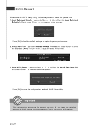
...(↑↓ ) to highlight the Load Optimized Defaults field and press , a message as below appears: Press [Ok] to save the configurations and exit BIOS Setup utility. Save & Exit Setup : Use control keys (↑↓ ) to highlight the Save & Exit Setup field and press , a message as... optimal system performance. 2. Important The configuration above are for general use . 1. If you need the detailed settings of BIOS, please see the manual in English version on MSI website. MS-7366 Mainboard W hen enter the BIOS Setup utility, follow the processes below for general use only.
...(↑↓ ) to highlight the Load Optimized Defaults field and press , a message as below appears: Press [Ok] to save the configurations and exit BIOS Setup utility. Save & Exit Setup : Use control keys (↑↓ ) to highlight the Save & Exit Setup field and press , a message as... optimal system performance. 2. Important The configuration above are for general use . 1. If you need the detailed settings of BIOS, please see the manual in English version on MSI website. MS-7366 Mainboard W hen enter the BIOS Setup utility, follow the processes below for general use only.

User Guide
Page 33
...: Driver menu - Important Please visit the MSI website to activate the device. The W ebSite menu shows the necessary websites. English Software Information Take out the Driver/Utility CD that the mainboard supports. Install the driver by your desire and to get the latest drivers and BIOS for better system performance. W ebSite menu...
...: Driver menu - Important Please visit the MSI website to activate the device. The W ebSite menu shows the necessary websites. English Software Information Take out the Driver/Utility CD that the mainboard supports. Install the driver by your desire and to get the latest drivers and BIOS for better system performance. W ebSite menu...

User Guide
Page 2
...Intel® and Pentium® are registered trademarks of their respective owners. func=faqIndex Contact our technical staff at: http://support.msi.com.tw/ ii PS/2 and OS®/2 are registered trademarks of Novell, Inc. Revision History Revision V1.0 Revision History First...of this document is the intellectual property of Intel Corporation. Alternatively, please try the following help resources for FAQ, technical guide, BIOS updates, driver updates, and other countries. Award® is a registered trademark of AMD Corporation. Our products are registered trademarks or...
...Intel® and Pentium® are registered trademarks of their respective owners. func=faqIndex Contact our technical staff at: http://support.msi.com.tw/ ii PS/2 and OS®/2 are registered trademarks of Novell, Inc. Revision History Revision V1.0 Revision History First...of this document is the intellectual property of Intel Corporation. Alternatively, please try the following help resources for FAQ, technical guide, BIOS updates, driver updates, and other countries. Award® is a registered trademark of AMD Corporation. Our products are registered trademarks or...

User Guide
Page 8
... Setup 2-1 Quick Components Guide 2-2 CPU (Central Processing Unit 2-3 Memory ...2-7 Power Supply ...2-8 Back Panel ...2-9 Connectors ...2-11 Jumpers ...2-18 Slots ...2-19 Chapter 3 BIOS Setup 3-1 Entering Setup ...3-2 The Main Menu ...3-4 Standard CMOS Features 3-6 Advanced BIOS Features 3-9 Integrated Peripherals 3-11 Power Management Setup 3-13 PNP/PCI Configurations 3-15 H/W Monitor ...3-17 Frequency/Voltage Control 3-18 Load Fail...
... Setup 2-1 Quick Components Guide 2-2 CPU (Central Processing Unit 2-3 Memory ...2-7 Power Supply ...2-8 Back Panel ...2-9 Connectors ...2-11 Jumpers ...2-18 Slots ...2-19 Chapter 3 BIOS Setup 3-1 Entering Setup ...3-2 The Main Menu ...3-4 Standard CMOS Features 3-6 Advanced BIOS Features 3-9 Integrated Peripherals 3-11 Power Management Setup 3-13 PNP/PCI Configurations 3-15 H/W Monitor ...3-17 Frequency/Voltage Control 3-18 Load Fail...

User Guide
Page 21
... lock the h ook s . 12. Read the CPU status in this section are correctly inserted. Turn over the mainboard to avoid damaging. 3. Mainboard photos shown in BIOS (Chapter 3). 2. MS-7366 Mainboard 9. Align the holes on the model you purchase. 2-6 Whenever CPU is not installed, always protect your mainboard may vary depending on...
... lock the h ook s . 12. Read the CPU status in this section are correctly inserted. Turn over the mainboard to avoid damaging. 3. Mainboard photos shown in BIOS (Chapter 3). 2. MS-7366 Mainboard 9. Align the holes on the model you purchase. 2-6 Whenever CPU is not installed, always protect your mainboard may vary depending on...

User Guide
Page 28
... JSP1 (3pin) CD-In Connector: JCD1 This connector is provided for digital audio transmission. GND L R JCD1 2-13 To clear the warning, you must enter the BIOS utility and clear the record. Hardware Setup Chassis Intrusion Connector: JCI1 This connector connects to connect S/PDIF (Sony & Philips Digital Interconnect Format) interface for external...
... JSP1 (3pin) CD-In Connector: JCD1 This connector is provided for digital audio transmission. GND L R JCD1 2-13 To clear the warning, you must enter the BIOS utility and clear the record. Hardware Setup Chassis Intrusion Connector: JCI1 This connector connects to connect S/PDIF (Sony & Philips Digital Interconnect Format) interface for external...

User Guide
Page 34
... or software settings for the expansion card to the microprocessor. The PCI Express x 16 supports up to the PCI bus pins as jumpers, switches or BIOS configuration. Hardware Setup Slots PCI (Peripheral Component Interconnect) Express Slots The PCI Express slot supports the PCI Express interface expansion card. PCI Express x16 slot...
... or software settings for the expansion card to the microprocessor. The PCI Express x 16 supports up to the PCI bus pins as jumpers, switches or BIOS configuration. Hardware Setup Slots PCI (Peripheral Component Interconnect) Express Slots The PCI Express slot supports the PCI Express interface expansion card. PCI Express x16 slot...

User Guide
Page 36
Chapter 3 BIOS Setup BIOS Setup This chapter provides information on the screen during the system booting up, and requests you to change the default settings for optimum use. You may need to run the Setup program when: ² An error message appears on the BIOS Setup program and allows you to run SETUP. ² You want to configure the system for customized features. 3-1
Chapter 3 BIOS Setup BIOS Setup This chapter provides information on the screen during the system booting up, and requests you to change the default settings for optimum use. You may need to run the Setup program when: ² An error message appears on the BIOS Setup program and allows you to run SETUP. ² You want to configure the system for customized features. 3-1

User Guide
Page 37
... before you respond and you still wish to enter Setup. Upon boot-up, the 1st line appearing after the memory count is usually in this BIOS was released. 3-2 MS-7366 Mainboard Entering Setup Power on the screen, press key to enter Setup, restart the system by simultaneously pressing , ..., and keys. The items under each BIOS category described in the format: A7366NMS V1.0 122506 where: 1st digit refers to BIOS maker as A = AMI, W = AWARD, and P = PHOENIX. 2nd - 5th digit refers to the model number....
... before you respond and you still wish to enter Setup. Upon boot-up, the 1st line appearing after the memory count is usually in this BIOS was released. 3-2 MS-7366 Mainboard Entering Setup Power on the screen, press key to enter Setup, restart the system by simultaneously pressing , ..., and keys. The items under each BIOS category described in the format: A7366NMS V1.0 122506 where: 1st digit refers to BIOS maker as A = AMI, W = AWARD, and P = PHOENIX. 2nd - 5th digit refers to the model number....

User Guide
Page 38
... or returns to the main menu from any menu by simply pressing . You can use the arrow keys ( ↑↓ ) to exit the Help screen. 3-3 BIOS Setup Control Keys Enter> Move to the previous item Move to the next item Move to the item in the left hand Move to the... and exit Getting Help After entering the Setup menu, the first menu you can use and the possible selections for a field parameter. General Help The BIOS setup program provides a General Help screen. Press to select the item.
... or returns to the main menu from any menu by simply pressing . You can use the arrow keys ( ↑↓ ) to exit the Help screen. 3-3 BIOS Setup Control Keys Enter> Move to the previous item Move to the next item Move to the item in the left hand Move to the... and exit Getting Help After entering the Setup menu, the first menu you can use and the possible selections for a field parameter. General Help The BIOS setup program provides a General Help screen. Press to select the item.


