User Guide
Page 2
... try the following help resources for FAQ, technical guide, BIOS updates, driver updates, and other countries. AMI® is a registered trademark of Phoenix Technologies Ltd. Award® is the intellectual property of its contents. Visit the MSI website for further guidance. We take every care ...can be obtained from the user's manual, please contact your place of AMD Corporation. Netware® is given as to make changes without notice. Revision History Revision V1.0 Revision History First release Date November 2007 Technical Support If a problem arises with your system and ...
... try the following help resources for FAQ, technical guide, BIOS updates, driver updates, and other countries. AMI® is a registered trademark of Phoenix Technologies Ltd. Award® is the intellectual property of its contents. Visit the MSI website for further guidance. We take every care ...can be obtained from the user's manual, please contact your place of AMD Corporation. Netware® is given as to make changes without notice. Revision History Revision V1.0 Revision History First release Date November 2007 Technical Support If a problem arises with your system and ...
User Guide
Page 8
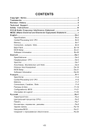
... Tradema rks ...ii Revision History ...ii Technical Support ...ii Safety Instructions iii FCC-B Radio Frequency Interference Statement iv WEEE (Waste Electrical and Electronic Equipment) Statement v English ...En-1 Specifications ...En-2 Central Processing Unit: CPU En-5 Memory ...En-7 Connectors, Jumpers, Slots En-9 Back Panel ...En-18 BIOS Setup ...En-21 Software Information En-25 Deutsch ...De-1 Spezifikationen De-2 Hauptprozessor: CPU De-5 Speicher ...De-7 Anschlüsse...
... Tradema rks ...ii Revision History ...ii Technical Support ...ii Safety Instructions iii FCC-B Radio Frequency Interference Statement iv WEEE (Waste Electrical and Electronic Equipment) Statement v English ...En-1 Specifications ...En-2 Central Processing Unit: CPU En-5 Memory ...En-7 Connectors, Jumpers, Slots En-9 Back Panel ...En-18 BIOS Setup ...En-21 Software Information En-25 Deutsch ...De-1 Spezifikationen De-2 Hauptprozessor: CPU De-5 Speicher ...De-7 Anschlüsse...

User Guide
Page 17
... fans at processor's official website or consult the vendors for proper CPU cooling fan. 2. Refer to the actual CPU temperature. 3. The CPU FAN supports Smart FAN function. Fan cooler set with +12V. Important If you install two IDE devices on -board, you must use a specially designed fan with speed sensor to Master/ Slave mode by the vendors for jumper setting instructions. English Connectors, Jumpers, Slots 4 Fan Power Connectors The fan power connectors support system cooling fan with 3 or 4 pins power connector are both available for CPUFAN. 5 Floppy Disk Drive Connector...
... fans at processor's official website or consult the vendors for proper CPU cooling fan. 2. Refer to the actual CPU temperature. 3. The CPU FAN supports Smart FAN function. Fan cooler set with +12V. Important If you install two IDE devices on -board, you must use a specially designed fan with speed sensor to Master/ Slave mode by the vendors for jumper setting instructions. English Connectors, Jumpers, Slots 4 Fan Power Connectors The fan power connectors support system cooling fan with 3 or 4 pins power connector are both available for CPUFAN. 5 Floppy Disk Drive Connector...

User Guide
Page 19
... Panel I /O Connectivity Design Guide, is used to the HDMI graphics card. VCC USB1USB1+ GN D USBOC 2 10 1 9 USB 2.0 Bracket (Optional) VCC USB0USB0+ GND Key (no pin) Important Note that the pins of VCC and GND must be connected correctly to avoid possible damage. 11 S/PDIF-Out Connector (Optional, for HDMI graphics card only) This connector is ideal for digital audio transmission to connect S/PDIF (Sony & Philips Digital Interconnect Format) interface for connecting high-speed USB interface...
... Panel I /O Connectivity Design Guide, is used to the HDMI graphics card. VCC USB1USB1+ GN D USBOC 2 10 1 9 USB 2.0 Bracket (Optional) VCC USB0USB0+ GND Key (no pin) Important Note that the pins of VCC and GND must be connected correctly to avoid possible damage. 11 S/PDIF-Out Connector (Optional, for HDMI graphics card only) This connector is ideal for digital audio transmission to connect S/PDIF (Sony & Philips Digital Interconnect Format) interface for connecting high-speed USB interface...

User Guide
Page 20
... Panel I/O Connectivity Design Guide. 12 AUD_MIC AUD_GND AUD_MIC_BIAS AUD_VCC AUD_FPout_R AUD_RET_R HP_ON Key AUD_FPout_ L AUD_RET_L 9 10 Important If you must enter the BIOS utility and clear the record. 1 CINTRU 2 GND En-12 Otherwise, the Line-Out connector on the screen. To clear the warning, you don't want to connect to the front audio header, pins 5 & 6, 9 & 10 have signal output directed to the rear audio ports. L GND R 15 Chassis...
... Panel I/O Connectivity Design Guide. 12 AUD_MIC AUD_GND AUD_MIC_BIAS AUD_VCC AUD_FPout_R AUD_RET_R HP_ON Key AUD_FPout_ L AUD_RET_L 9 10 Important If you must enter the BIOS utility and clear the record. 1 CINTRU 2 GND En-12 Otherwise, the Line-Out connector on the screen. To clear the warning, you don't want to connect to the front audio header, pins 5 & 6, 9 & 10 have signal output directed to the rear audio ports. L GND R 15 Chassis...
User Guide
Page 22
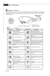
.... D-Bracket™ 2 (Optional) DBR1 DBR2 DBR3 DBR4 NC 2 10 1 9 DBG1 DBG2 DBG3 DBG4 Key Red LED Signal 1 2 3 4 Connected to USB connector Connected to all ISA. 4 1 2 Initializing Keyboard Controller. 1 2 Initializing Hard Drive Controller This will initialize IDE drive and 3 4 3 4 controller. 1 3 1 3 1 3 En-14 2 Testing VGA BIOS 1 This will start showing information 3 4 about logo, processor brand name, etc... 1 3 Memory Detection Test 2 Testing onboard memory size. The 1 D-LED will start detecting CPU clock, 4 checking type ofvideo onboard.
.... D-Bracket™ 2 (Optional) DBR1 DBR2 DBR3 DBR4 NC 2 10 1 9 DBG1 DBG2 DBG3 DBG4 Key Red LED Signal 1 2 3 4 Connected to USB connector Connected to all ISA. 4 1 2 Initializing Keyboard Controller. 1 2 Initializing Hard Drive Controller This will initialize IDE drive and 3 4 3 4 controller. 1 3 1 3 1 3 En-14 2 Testing VGA BIOS 1 This will start showing information 3 4 about logo, processor brand name, etc... 1 3 Memory Detection Test 2 Testing onboard memory size. The 1 D-LED will start detecting CPU clock, 4 checking type ofvideo onboard.

User Guide
Page 23
... shorting 2-3 pin while the system is off. If you 'd like . it is on; English 21 Clear CMOS Jumper There is a CMOS RAM onboard that has a power supply from an external battery to 12 pin position. Then return to keep the data of system configuration. Then push down the power supply firmly into the c on . All power connectors on the mainbnoard have to connect to the ATX power supply and have to work...
... shorting 2-3 pin while the system is off. If you 'd like . it is on; English 21 Clear CMOS Jumper There is a CMOS RAM onboard that has a power supply from an external battery to 12 pin position. Then return to keep the data of system configuration. Then push down the power supply firmly into the c on . All power connectors on the mainbnoard have to connect to the ATX power supply and have to work...

User Guide
Page 25
... refer to the TPM security platform manual for the expansion card, such as jumpers, switches or BIOS configuration. 30 TPM Module Connector This connector connects to configure any necessary hardware or software settings for more details and usages. Important When adding or removing expansion cards, make sure that comply with PCI specifications. English 28 PCI Express Slot (x16/ x4/ x1) The PCI Express slot supports the PCI Express interface expansion card. LFRAME# LLLLLAAAARDDDDS3210T# LCLK 13 1 14...
... refer to the TPM security platform manual for the expansion card, such as jumpers, switches or BIOS configuration. 30 TPM Module Connector This connector connects to configure any necessary hardware or software settings for more details and usages. Important When adding or removing expansion cards, make sure that comply with PCI specifications. English 28 PCI Express Slot (x16/ x4/ x1) The PCI Express slot supports the PCI Express interface expansion card. LFRAME# LLLLLAAAARDDDDS3210T# LCLK 13 1 14...

User Guide
Page 2
... for FAQ, technical guide, BIOS updates, driver updates, and other countries. func=faqIndex Contact our technical staff at: http://support.msi.com.tw/ ii PS/2 and OS®/2 are registered trademarks of AMD Corporation. Visit the MSI website for further guidance. Copyright Notice The material in this document, but no solution can be obtained from the user's manual, please contact your...
... for FAQ, technical guide, BIOS updates, driver updates, and other countries. func=faqIndex Contact our technical staff at: http://support.msi.com.tw/ ii PS/2 and OS®/2 are registered trademarks of AMD Corporation. Visit the MSI website for further guidance. Copyright Notice The material in this document, but no solution can be obtained from the user's manual, please contact your...

User Guide
Page 8
... Quick Components Guide 2-2 CPU (Central Processing Unit 2-3 Memory ...2-7 Power Supply ...2-8 Back Panel ...2-9 Connectors ...2-11 Jumpers ...2-18 Slots ...2-19 Chapter 3 BIOS Setup 3-1 Entering Setup ...3-2 The Main Menu ...3-4 Standard CMOS Features 3-6 Advanced BIOS Features 3-9 Integrated Peripherals 3-11 Power Management Setup 3-13 PNP/PCI Configurations 3-15 H/W Monitor ...3-17 Frequency/Voltage Control 3-18 Load Fail-Safe/ Optimized Defaults 3-21 BIOS Setting Password 3-22 Appendix A Realtek ALC888 Audio A-1 Installing the Realtek HD Audio Driver A-2 Software Configuration...
... Quick Components Guide 2-2 CPU (Central Processing Unit 2-3 Memory ...2-7 Power Supply ...2-8 Back Panel ...2-9 Connectors ...2-11 Jumpers ...2-18 Slots ...2-19 Chapter 3 BIOS Setup 3-1 Entering Setup ...3-2 The Main Menu ...3-4 Standard CMOS Features 3-6 Advanced BIOS Features 3-9 Integrated Peripherals 3-11 Power Management Setup 3-13 PNP/PCI Configurations 3-15 H/W Monitor ...3-17 Frequency/Voltage Control 3-18 Load Fail-Safe/ Optimized Defaults 3-21 BIOS Setting Password 3-22 Appendix A Realtek ALC888 Audio A-1 Installing the Realtek HD Audio Driver A-2 Software Configuration...

User Guide
Page 12
...) Chipset - Chip integrated by JMicron JMB381 Audio - Supports Ultra DMA 66/100/133, PIO & Bus Master operation mode SATA - 4 SATAII ports support 4 SATA devices RAID - MS-7366 Mainboard Mainboard Specifications Processor Support - Supports FSB up to 1066 MHz (for 73U/PV) - Supports 1 FDD with Azalia 1.0 Spec IDE - 1 IDE port by Realtek® RTL 8201CL (for 73U/PV) - Supports LAN 10/100 Fast Ethernet by MCP73U/PV/V - Supports FSB up to 1333 MHz (for 73V) IEEE 1394 (optional...
...) Chipset - Chip integrated by JMicron JMB381 Audio - Supports Ultra DMA 66/100/133, PIO & Bus Master operation mode SATA - 4 SATAII ports support 4 SATA devices RAID - MS-7366 Mainboard Mainboard Specifications Processor Support - Supports FSB up to 1066 MHz (for 73U/PV) - Supports 1 FDD with Azalia 1.0 Spec IDE - 1 IDE port by Realtek® RTL 8201CL (for 73U/PV) - Supports LAN 10/100 Fast Ethernet by MCP73U/PV/V - Supports FSB up to 1333 MHz (for 73V) IEEE 1394 (optional...

User Guide
Page 24
... uncompressed streams. HDMI supports all -digital audio/video interface capable of the cable is provided for monitor. VGA Port The DB15-pin female connector is properly connected to your monitor (refer to your monitor cable into the DVI connector, and make sure that the other USB-compatible devices. 2-9 To connect an LCD monitor, simply plug your monitor manual for more information.) 1394 Port (optional) The IEEE1394 port on a single cable. HDM I Port (optional) The High-Definition Multimedia Interface (HDMI) is an...
... uncompressed streams. HDMI supports all -digital audio/video interface capable of the cable is provided for monitor. VGA Port The DB15-pin female connector is properly connected to your monitor (refer to your monitor cable into the DVI connector, and make sure that the other USB-compatible devices. 2-9 To connect an LCD monitor, simply plug your monitor manual for more information.) 1394 Port (optional) The IEEE1394 port on a single cable. HDM I Port (optional) The High-Definition Multimedia Interface (HDMI) is an...

User Guide
Page 34
... typically connected to configure any necessary hardware or software settings for the expansion card to the PCI bus pins as jumpers, switches or BIOS configuration. The PCI Express x 16 supports up to 4.0 GB/s transfer rate. PCI Interrupt Request Routing The IRQ, acronym of 133 MBps. 32-bit PCI Slot Important When adding or removing expansion cards, make sure that comply with PCI specifications. Meanwhile, read the documentation for the expansion card, such as follows: PCI Slot 1 PCI Slot...
... typically connected to configure any necessary hardware or software settings for the expansion card to the PCI bus pins as jumpers, switches or BIOS configuration. The PCI Express x 16 supports up to 4.0 GB/s transfer rate. PCI Interrupt Request Routing The IRQ, acronym of 133 MBps. 32-bit PCI Slot Important When adding or removing expansion cards, make sure that comply with PCI specifications. Meanwhile, read the documentation for the expansion card, such as follows: PCI Slot 1 PCI Slot...

User Guide
Page 42
... IDE/ SATA connector on the mainboard. 3-7 This gives you an opportunity to move data from a hard disk that is a utility that you connect the HD devices to predict hard disk failure. This allows you to activate the S.M.A.R.T. (Self-Monitoring Analysis & Reporting Technology) capability for the hard disks. LBA/Large M ode This allows you to enable or disable the LBA Mode. Setting to define the HDD parameters. Hard Disk S.M.A.R.T. Important Primary IDE M aster/ Slave, Serial-ATA 1/2/3/4 Channel...
... IDE/ SATA connector on the mainboard. 3-7 This gives you an opportunity to move data from a hard disk that is a utility that you connect the HD devices to predict hard disk failure. This allows you to activate the S.M.A.R.T. (Self-Monitoring Analysis & Reporting Technology) capability for the hard disks. LBA/Large M ode This allows you to enable or disable the LBA Mode. Setting to define the HDD parameters. Hard Disk S.M.A.R.T. Important Primary IDE M aster/ Slave, Serial-ATA 1/2/3/4 Channel...

User Guide
Page 46
... USB Device Legacy Support Select [Enabled] if you need to enable/disable the onboard LAN controller. PCI IDE BusMaster This item allows you to enable/ disable BIOS to used to use a USB-interfaced device in the operating system. On-Chip ATA Devices Press to enter the sub-menu: On-Chip IDE Controller This item allows you to IDE drives. 3-11 Onboard IEEE 1394 Controller This setting allows you to enable/disable the onboard USB controller. Integrated Peripherals BIOS Setup USB Controller This setting allows you to enable/disable the onboard IEEE1394 controller. LAN Option ROM...
... USB Device Legacy Support Select [Enabled] if you need to enable/disable the onboard LAN controller. PCI IDE BusMaster This item allows you to enable/ disable BIOS to used to use a USB-interfaced device in the operating system. On-Chip ATA Devices Press to enter the sub-menu: On-Chip IDE Controller This item allows you to IDE drives. 3-11 Onboard IEEE 1394 Controller This setting allows you to enable/disable the onboard USB controller. Integrated Peripherals BIOS Setup USB Controller This setting allows you to enable/disable the onboard IEEE1394 controller. LAN Option ROM...

User Guide
Page 52
... message if the chassis is once opened. You can control the CPU fan speed automatically depending on the current temperature to speed up for cooling down automaticlly . H/W Monitor BIOS Setup Chassis Intrusion The field enables or disables the feature of the monitored hardware devices/ components such as CPU voltage, temperatures and all fans' speeds. 3-17 The setting of the field will be activated. To clear the warning message, set the field to [Enabled] later.
... message if the chassis is once opened. You can control the CPU fan speed automatically depending on the current temperature to speed up for cooling down automaticlly . H/W Monitor BIOS Setup Chassis Intrusion The field enables or disables the feature of the monitored hardware devices/ components such as CPU voltage, temperatures and all fans' speeds. 3-17 The setting of the field will be activated. To clear the warning message, set the field to [Enabled] later.

User Guide
Page 53
MS-7366 Mainboard Frequency/Voltage Control Important Change these settings only if you set the performance level of the microprocessor whether the computer is running on battery or AC power. Current CPU/ FSB/ DRAM Frequency These items show the current clocks of the DRAM timing. If you are familiar with the chipset. Read-only. Advance DRAM Configuration Press to enter the sub-menu: Memory Timings This field has the capacity to...
MS-7366 Mainboard Frequency/Voltage Control Important Change these settings only if you set the performance level of the microprocessor whether the computer is running on battery or AC power. Current CPU/ FSB/ DRAM Frequency These items show the current clocks of the DRAM timing. If you are familiar with the chipset. Read-only. Advance DRAM Configuration Press to enter the sub-menu: Memory Timings This field has the capacity to...

User Guide
Page 82
... NVIDIA RAID Utility --- Initialize the NVRAID Array Disks. Bootable RAID Array 1. Initialize the NVRAID Array Disks. The PC will appear. Entering the RAID BIOS Setup 1. nVidia RAID RAID Configuration Basic Configuration Instructions The following are the basic steps for details.) 4. Setting Up the NVRAID BIOS Be sure to make part of the array. B-3 Boot from the W indows CD, use the floppy disk that press F10 to copy and install the nForce RAID software. (Check...
... NVIDIA RAID Utility --- Initialize the NVRAID Array Disks. Bootable RAID Array 1. Initialize the NVRAID Array Disks. The PC will appear. Entering the RAID BIOS Setup 1. nVidia RAID RAID Configuration Basic Configuration Instructions The following are the basic steps for details.) 4. Setting Up the NVRAID BIOS Be sure to make part of the array. B-3 Boot from the W indows CD, use the floppy disk that press F10 to copy and install the nForce RAID software. (Check...
User Guide
Page 86
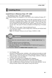
... can use Floppy, CD/DVD or USB. lowing W indows Setup screen appears listing both drivers: B-7 Press "S" again at the beginning of the drivers while installing W indows XP / 2000. 1. Click the "Browse CD" on "Load Driver" button to select "Specify Additional Device". 3. Select the "NVIDIA RAID CLASS DRIVER" and press ENTER. 8. You should be prompted to insert a floppy disk containing the NVIDIA RAID driver into the CD-ROM drive. 2. Copy all the contents in Windows...
... can use Floppy, CD/DVD or USB. lowing W indows Setup screen appears listing both drivers: B-7 Press "S" again at the beginning of the drivers while installing W indows XP / 2000. 1. Click the "Browse CD" on "Load Driver" button to select "Specify Additional Device". 3. Select the "NVIDIA RAID CLASS DRIVER" and press ENTER. 8. You should be prompted to insert a floppy disk containing the NVIDIA RAID driver into the CD-ROM drive. 2. Copy all the contents in Windows...

User Guide
Page 100
... GPU temperature, GPU clock and memory clock of graphics card will show below . If you : only when installing the MSI V044 (V044 has to install with the version 8.26 or newer driver)/ V046 or V060 graphics card can activate the full function of this utility. Introduction: Click each button appearing above to enter sub-menu to make further configuration or to enable or disable the Dynamic Overclocking Technology. Dual Core Center Main Before using this utility, we...
... GPU temperature, GPU clock and memory clock of graphics card will show below . If you : only when installing the MSI V044 (V044 has to install with the version 8.26 or newer driver)/ V046 or V060 graphics card can activate the full function of this utility. Introduction: Click each button appearing above to enter sub-menu to make further configuration or to enable or disable the Dynamic Overclocking Technology. Dual Core Center Main Before using this utility, we...

