
User Guide
Page 3
... not work according to the power inlet. ■ Place the power cord such a way that could damage or cause electrical shock. ■ If any - iii MS-7581 Safety Instructions ■ Always read the safety instructions carefully. ■ Keep this User's Manual for future reference. ■ Keep this equipment away from humidity. ■...
... not work according to the power inlet. ■ Place the power cord such a way that could damage or cause electrical shock. ■ If any - iii MS-7581 Safety Instructions ■ Always read the safety instructions carefully. ■ Keep this User's Manual for future reference. ■ Keep this equipment away from humidity. ■...

User Guide
Page 4
... the dealer or an experienced radio/television technician for compliance could void the user's authority to Part 15 of the FCC Rules. Micro-Star International MS-7581 This device complies with Part 15 of the FCC Rules. Operation is subject to the following two conditions: 1) this device may not cause harmful interference...
... the dealer or an experienced radio/television technician for compliance could void the user's authority to Part 15 of the FCC Rules. Micro-Star International MS-7581 This device complies with Part 15 of the FCC Rules. Operation is subject to the following two conditions: 1) this device may not cause harmful interference...

User Guide
Page 5
... électroniques ne peuvent être déposés dans les décharges ou tout simplement mis à la poubelle. DEUTSCH Hinweis von MSI zur Erhaltung und Schutz unserer Umwelt Gemäß der Richtlinie 2002/96/EG über Elektro- FRANÇAIS En tant qu'écologiste... à rappeler ceci... MSI prendra en compte cette exigence relative au retour des produits en fin de vie au sein de la communauté européenne. Par conséquent vous pouvez retourner localement ces matériels dans les points de collecte. MS-7581 WEEE (Waste Electrical and Electronic ...
... électroniques ne peuvent être déposés dans les décharges ou tout simplement mis à la poubelle. DEUTSCH Hinweis von MSI zur Erhaltung und Schutz unserer Umwelt Gemäß der Richtlinie 2002/96/EG über Elektro- FRANÇAIS En tant qu'écologiste... à rappeler ceci... MSI prendra en compte cette exigence relative au retour des produits en fin de vie au sein de la communauté européenne. Par conséquent vous pouvez retourner localement ces matériels dans les points de collecte. MS-7581 WEEE (Waste Electrical and Electronic ...
User Guide
Page 9
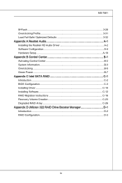
MS-7581 M-Flash 3-28 Overclocking Profile 3-31 Load Fail-Safe/ Optimized Defaults 3-32 Appendix A Realtek Audio A-1 Installing the Realtek HD Audio Driver A-2 Software Configuration A-4 Hardware Setup A-19 ...
MS-7581 M-Flash 3-28 Overclocking Profile 3-31 Load Fail-Safe/ Optimized Defaults 3-32 Appendix A Realtek Audio A-1 Installing the Realtek HD Audio Driver A-2 Software Configuration A-4 Hardware Setup A-19 ...

User Guide
Page 11
Chapter 1 Getting Started Thank you for optimal system efficiency. The P55-GD80 Series mainboards are based on Intel® P55 chipsets for choosing the P55-GD80 Series (MS-7581 v1.X) ATX mainboard. Designed to fit the advanced Intel® i5/ i7 LGA1156 processor, the P55-GD80 Series deliver a high performance and professional desktop platform solution. 1-1-1
Chapter 1 Getting Started Thank you for optimal system efficiency. The P55-GD80 Series mainboards are based on Intel® P55 chipsets for choosing the P55-GD80 Series (MS-7581 v1.X) ATX mainboard. Designed to fit the advanced Intel® i5/ i7 LGA1156 processor, the P55-GD80 Series deliver a high performance and professional desktop platform solution. 1-1-1
User Guide
Page 13
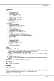
...will unavailable when an expansion card was installed into PCI_ E5 slot. ■ 2 PCI slots, support 3.3V/ 5V PCI bus Interface Form Factor ■ ATX (30.5cm X 24.4 cm) Mounting ■ 9 mounting holes If you need to purchase accessories and request the part numbers, you intend to install ... you could search the product web page and find details on our web address below http://www.msi.com/index.php 1-3 all PCIE x1 slots will auto arrange from x16/ x0 to PCIE 2.0 x4 speed - MS-7581 Connectors ■ Back panel - 1 PS/2 keyboard port - 1 PS/2 mouse port - 1 Coaxial S/PDIF-out port - 1...
...will unavailable when an expansion card was installed into PCI_ E5 slot. ■ 2 PCI slots, support 3.3V/ 5V PCI bus Interface Form Factor ■ ATX (30.5cm X 24.4 cm) Mounting ■ 9 mounting holes If you need to purchase accessories and request the part numbers, you intend to install ... you could search the product web page and find details on our web address below http://www.msi.com/index.php 1-3 all PCIE x1 slots will auto arrange from x16/ x0 to PCIE 2.0 x4 speed - MS-7581 Connectors ■ Back panel - 1 PS/2 keyboard port - 1 PS/2 mouse port - 1 Coaxial S/PDIF-out port - 1...

User Guide
Page 14
▍ Getting Started Mainboard Layout P55-GD80 Series (MS-7581 v1.X) ATX Mainboard 1-4
▍ Getting Started Mainboard Layout P55-GD80 Series (MS-7581 v1.X) ATX Mainboard 1-4

User Guide
Page 15
Packing Checklist MS-7581 MSI mainboard MSI Driver/Utility DVD SATA Cable Power Cable USB Bracket (Optional) Standard Cable for IDE Devices V-Check Cable CrossFireX Video Link Cable SLI Video Link Card Back IO Shield User's Guide * The pictures are for reference only and may vary from the packing contents of the product you purchased. 1-5
Packing Checklist MS-7581 MSI mainboard MSI Driver/Utility DVD SATA Cable Power Cable USB Bracket (Optional) Standard Cable for IDE Devices V-Check Cable CrossFireX Video Link Cable SLI Video Link Card Back IO Shield User's Guide * The pictures are for reference only and may vary from the packing contents of the product you purchased. 1-5
User Guide
Page 19
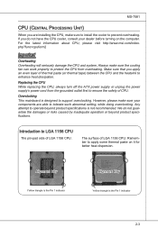
...1156 CPU The pin-pad side of CPU. For the latest information about CPU, please visit http://www.msi.com/index. Replacing the CPU While replacing the CPU, always turn off the ATX power supply or unplug the power supply's power cord from overheating. The surface of thermal paste (or ...1156 CPU. Alignment Key Yellow triangle is the Pin 1 indicator Alignment Key Yellow triangle is designed to tolerate such abnormal setting, while doing overclocking. MS-7581 CPU (Central Processing Unit) When you apply an even layer of LGA 1156 CPU. If you do not guarantee the damages or risks caused ...
...1156 CPU The pin-pad side of CPU. For the latest information about CPU, please visit http://www.msi.com/index. Replacing the CPU While replacing the CPU, always turn off the ATX power supply or unplug the power supply's power cord from overheating. The surface of thermal paste (or ...1156 CPU. Alignment Key Yellow triangle is the Pin 1 indicator Alignment Key Yellow triangle is designed to tolerate such abnormal setting, while doing overclocking. MS-7581 CPU (Central Processing Unit) When you apply an even layer of LGA 1156 CPU. If you do not guarantee the damages or risks caused ...

User Guide
Page 21
Secure the lever near the hook end under the retention tab. 8. Important • Confirm if your system. • Do not touch the CPU socket pins to avoid damaging. 2-5 If not, take out the CPU with pure vertical motion and reinstall. 6. Make sure the four hooks are in porper position before turning on your CPU cooler is seated well into the socket. Visually inspect if the CPU is firmly installed before you install the cooler. Engage the load lever while pressing down lightly onto the load plate. Alignment Key 7. MS-7581 5.
Secure the lever near the hook end under the retention tab. 8. Important • Confirm if your system. • Do not touch the CPU socket pins to avoid damaging. 2-5 If not, take out the CPU with pure vertical motion and reinstall. 6. Make sure the four hooks are in porper position before turning on your CPU cooler is seated well into the socket. Visually inspect if the CPU is firmly installed before you install the cooler. Engage the load lever while pressing down lightly onto the load plate. Alignment Key 7. MS-7581 5.

User Guide
Page 23
...be detected up to the following illustrations explain the population rules for installing memory modules. The following illustrations for memory population rules. MS-7581 Memory These DIMM slots are used for Dual-Channel mode. 1 DIMM2 DIMM1 DIMM4 DIMM3 2 DIMM2 DIMM1 DIMM4 DIMM3 Installed Empty ... mode can transmit and receive data with a 4GB memory module. 2-7 For more information on compatible components, please visit http://www.msi.com/index.php?func=testreport DDR3 240-pin, 1.5V 48x2=96 pin 72x2=144 pin Memory Population Rule Please refer to 15...
...be detected up to the following illustrations explain the population rules for installing memory modules. The following illustrations for memory population rules. MS-7581 Memory These DIMM slots are used for Dual-Channel mode. 1 DIMM2 DIMM1 DIMM4 DIMM3 2 DIMM2 DIMM1 DIMM4 DIMM3 Installed Empty ... mode can transmit and receive data with a 4GB memory module. 2-7 For more information on compatible components, please visit http://www.msi.com/index.php?func=testreport DDR3 240-pin, 1.5V 48x2=96 pin 72x2=144 pin Memory Population Rule Please refer to 15...

User Guide
Page 25
MS-7581 Power Supply ATX 24-pin Power Connector: JPWR1 This connector allows you to ensure stable operation of the mainboard. • Power supply of the power supply is inserted in the proper orientation and the pins are connected to proper ATX power supplies to connect an ATX 24-pin power supply. You may use... the 20-pin ATX power supply, please plug your power supply along with pin 1 & pin 13. 1.+23.+3.33.G4V.3.r+...
MS-7581 Power Supply ATX 24-pin Power Connector: JPWR1 This connector allows you to ensure stable operation of the mainboard. • Power supply of the power supply is inserted in the proper orientation and the pins are connected to proper ATX power supplies to connect an ATX 24-pin power supply. You may use... the 20-pin ATX power supply, please plug your power supply along with pin 1 & pin 13. 1.+23.+3.33.G4V.3.r+...

User Guide
Page 27
...-Out (Green) - Line Out, is a connector for connection to Yellow the Local Area Network (LAN). Rear-Surround Out in 5.1/ 7.1 channel mode. ■ SS-Out (Gray) - MS-7581 ▶ LAN The standard RJ-45 LAN jack is for speakers or headphones. ■ Mic (Pink) - Center/ Subwoofer Out in 4/ 5.1/ 7.1 channel mode. ■ CS-Out...
...-Out (Green) - Line Out, is a connector for connection to Yellow the Local Area Network (LAN). Rear-Surround Out in 5.1/ 7.1 channel mode. ■ SS-Out (Gray) - MS-7581 ▶ LAN The standard RJ-45 LAN jack is for speakers or headphones. ■ Mic (Pink) - Center/ Subwoofer Out in 4/ 5.1/ 7.1 channel mode. ■ CS-Out...
User Guide
Page 29
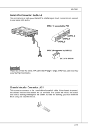
... opMpySDIFlopMpySDI Kdkldkddfkkakfskkdskkdakaddfdddffdfka-ddkdffdldkddjdafdsdddjfdddffkadadsfdddffdfadasfadfsddsddadasdsaddsdafsddadsdddfdsadddfffaffsfsdasfdfffdf K dk ldkddf kkakfskkdskkdakaddfdddffdfka-ddkdffdldkddj adfdsdddjdfddf kadfadsf dddfafdfdasfsadfddsddadasdsaddsdafsddadsdddfdsadddffffafsfsdafsdf f fdf SATA1~6 supported by P55 SATA1_2 SATA3_4 SATA5_6 SATA7/8 supported by JMB322 SATA7 & SATA8 Important Please do not fold the Serial ATA cable into 90-degree angle. MS-7581 Serial ATA Connector: SATA1~8 This connector is opened, the chassis intrusion mechanism will record...
... opMpySDIFlopMpySDI Kdkldkddfkkakfskkdskkdakaddfdddffdfka-ddkdffdldkddjdafdsdddjfdddffkadadsfdddffdfadasfadfsddsddadasdsaddsdafsddadsdddfdsadddfffaffsfsdasfdfffdf K dk ldkddf kkakfskkdskkdakaddfdddffdfka-ddkdffdldkddj adfdsdddjdfddf kadfadsf dddfafdfdasfsadfddsddadasdsaddsdafsddadsdddfdsadddffffafsfsdafsdf f fdf SATA1~6 supported by P55 SATA1_2 SATA3_4 SATA5_6 SATA7/8 supported by JMB322 SATA7 & SATA8 Important Please do not fold the Serial ATA cable into 90-degree angle. MS-7581 Serial ATA Connector: SATA1~8 This connector is opened, the chassis intrusion mechanism will record...

User Guide
Page 31
... JFP1 1.+3.-5.-7.H+9D.RDReLseEesDrevteSdwitch SpeakeBr2uz.z-e4r.+6.-8.+ JFP2 1.G3.rSo5uu.Psn7opd.NweonedrPLLinEEDD IEEE1394 Connector: J1394_1 (Optional) This connector allows you to the front panel switches and LEDs. MS-7581 Front Panel Connectors: JFP1, JFP2 These connectors are for electrical connection to connect the IEEE1394 device via an optional IEEE1394 bracket. 2.T4P.GA6-.rTo8Pu1.+nB01d...
... JFP1 1.+3.-5.-7.H+9D.RDReLseEesDrevteSdwitch SpeakeBr2uz.z-e4r.+6.-8.+ JFP2 1.G3.rSo5uu.Psn7opd.NweonedrPLLinEEDD IEEE1394 Connector: J1394_1 (Optional) This connector allows you to the front panel switches and LEDs. MS-7581 Front Panel Connectors: JFP1, JFP2 These connectors are for electrical connection to connect the IEEE1394 device via an optional IEEE1394 bracket. 2.T4P.GA6-.rTo8Pu1.+nB01d...

User Guide
Page 33
MS-7581 S/PDIF-Out Connector: JSP1 This connector is used to connect S/PDIF (Sony & Philips Digital Interconnect Format) interface for digital audio transmission. 1.V2C.S3C.PGDrIoFund S/PDIF Bracket (Optional) Front Panel Audio Connector: JAUD1 This connector allows you to connect the front panel audio and is compliant with Intel® Front Panel I/O Connectivity Design Guide. 2.G4r.oP6uR.Mn8Ed.1INSC0Eo.DHNPeeCitnaeEdc#tPiohnone Detection 1.M3.IMC5.ILHC7e.RS9a.EdHNPeShaEodn_PeShERoNneDL 2-17
MS-7581 S/PDIF-Out Connector: JSP1 This connector is used to connect S/PDIF (Sony & Philips Digital Interconnect Format) interface for digital audio transmission. 1.V2C.S3C.PGDrIoFund S/PDIF Bracket (Optional) Front Panel Audio Connector: JAUD1 This connector allows you to connect the front panel audio and is compliant with Intel® Front Panel I/O Connectivity Design Guide. 2.G4r.oP6uR.Mn8Ed.1INSC0Eo.DHNPeeCitnaeEdc#tPiohnone Detection 1.M3.IMC5.ILHC7e.RS9a.EdHNPeShaEodn_PeShERoNneDL 2-17

User Guide
Page 35
GreenPower Genie Connector: JSMB1 (optional) This connector connects to GreenPower Genie (optional). 2.4S.MNBo PDianta 1.S3M.GBroCulnodck 2-19 Please refer to the D-LED2 quick guide (optional) for you and identify the current status or mode of the connected system. MS-7581 D-LED2 Panel Connector: JDLED2 (optional) This connector connects to a D-LED2 (Debug-LED2) panel (optional), which shows information on the panel for more details and usages.
GreenPower Genie Connector: JSMB1 (optional) This connector connects to GreenPower Genie (optional). 2.4S.MNBo PDianta 1.S3M.GBroCulnodck 2-19 Please refer to the D-LED2 quick guide (optional) for you and identify the current status or mode of the connected system. MS-7581 D-LED2 Panel Connector: JDLED2 (optional) This connector connects to a D-LED2 (Debug-LED2) panel (optional), which shows information on the panel for more details and usages.

User Guide
Page 37
...press this button to reset the system, the system will switch the LED between on or turn -off mode. Plus button Minus button 2-21 MS-7581 Power On Button: POWER This button is used to switch LED function of system. Green Power Button: Green Power This button is used to ...reset the system. This limitation derives from the P55 internal function. Important If you press the button, the system will be forced shutdown about 4 seconds and restarted. Base Clock Control Buttons: Plus,...
...press this button to reset the system, the system will switch the LED between on or turn -off mode. Plus button Minus button 2-21 MS-7581 Power On Button: POWER This button is used to switch LED function of system. Green Power Button: Green Power This button is used to ...reset the system. This limitation derives from the P55 internal function. Important If you press the button, the system will be forced shutdown about 4 seconds and restarted. Base Clock Control Buttons: Plus,...

User Guide
Page 39
... CPU_VTT GND point by using a multimeter. CPU GND CPU_VTT voltage: measure the current CPU_ VTT voltage with CPU point and GND point by using a mul- MS-7581 Voltage Check Point: V_Check Point This voltage check point set is used to measure the current CPU/ CPU_VTT/ DDR/ PCH voltage. timeter. PCH GND 2-23...
... CPU_VTT GND point by using a multimeter. CPU GND CPU_VTT voltage: measure the current CPU_ VTT voltage with CPU point and GND point by using a mul- MS-7581 Voltage Check Point: V_Check Point This voltage check point set is used to measure the current CPU/ CPU_VTT/ DDR/ PCH voltage. timeter. PCH GND 2-23...
User Guide
Page 41
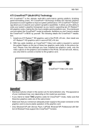
...'s graphics capabilities. CrossFireXTM Video Link cable Important • Mainboard photos shown in this graphics card. The mainboard can auto detect the CrossFireXTM mode by yourself. MS-7581 ATI CrossFireXTM (Multi-GPU) Technology ATI CrossFireXTM is required to connect the golden fingers on the top of these two graphics cards are for CrossFireXTM...
...'s graphics capabilities. CrossFireXTM Video Link cable Important • Mainboard photos shown in this graphics card. The mainboard can auto detect the CrossFireXTM mode by yourself. MS-7581 ATI CrossFireXTM (Multi-GPU) Technology ATI CrossFireXTM is required to connect the golden fingers on the top of these two graphics cards are for CrossFireXTM...


