User Guide
Page 2
... trademark of MICRO-STAR INTERNATIONAL. We take every care in this document, but no solution can be obtained from the user's manual, please contact your place of its contents. Revision History Revision V1.0 Revision History First release for FAQ, technical guide, BIOS updates, driver updates, and other information: http://www.msi.com/index.php?func=service ◙ Contact our technical...
... trademark of MICRO-STAR INTERNATIONAL. We take every care in this document, but no solution can be obtained from the user's manual, please contact your place of its contents. Revision History Revision V1.0 Revision History First release for FAQ, technical guide, BIOS updates, driver updates, and other information: http://www.msi.com/index.php?func=service ◙ Contact our technical...
User Guide
Page 8
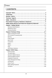
... History ii Technical Support ii Safety Instructions iii FCC-B Radio Frequency Interference Statement iv WEEE (Waste Electrical and Electronic Equipment) Statement v Chapter 1 Getting Started 1-1 Mainboard Specifications 1-2 Mainboard Layout 1-4 Packing Checklist 1-5 Chapter 2 Hardware Setup 2-1 Quick Components Guide 2-2 CPU (Central Processing Unit 2-3 Memory 2-7 Power Supply 2-9 Back Panel 2-10 Connectors 2-12 Button 2-20 Switch 2-22 Slots 2-24 LED Status Indicators 2-30 Chapter 3 BIOS Setup 3-1 Entering Setup 3-2 The Main Menu 3-4 Standard CMOS Features 3-6 Advanced...
... History ii Technical Support ii Safety Instructions iii FCC-B Radio Frequency Interference Statement iv WEEE (Waste Electrical and Electronic Equipment) Statement v Chapter 1 Getting Started 1-1 Mainboard Specifications 1-2 Mainboard Layout 1-4 Packing Checklist 1-5 Chapter 2 Hardware Setup 2-1 Quick Components Guide 2-2 CPU (Central Processing Unit 2-3 Memory 2-7 Power Supply 2-9 Back Panel 2-10 Connectors 2-12 Button 2-20 Switch 2-22 Slots 2-24 LED Status Indicators 2-30 Chapter 3 BIOS Setup 3-1 Entering Setup 3-2 The Main Menu 3-4 Standard CMOS Features 3-6 Advanced...

User Guide
Page 12
... 1.0 Spec IDE ■ 1 IDE port by JMicron® JMB363 ■ Supports Ultra DMA 66/100/133 mode ■ Supports PIO, Bus Master operation mode SATA ■ 6 SATAII (SATA1~6) ports by Intel® P55 ■ 2 SATAII (SATA7, SATA8) ports by JMicron® JMB322 ■ 1 ESATA/ USB Combo port (back panel) by JMicron® JMB363 ■ Supports storage and data transfers at up to 3 Gb/s RAID ■ SATA1~6 support Intel® Matrix Storage Technology (AHCI/ RAID...
... 1.0 Spec IDE ■ 1 IDE port by JMicron® JMB363 ■ Supports Ultra DMA 66/100/133 mode ■ Supports PIO, Bus Master operation mode SATA ■ 6 SATAII (SATA1~6) ports by Intel® P55 ■ 2 SATAII (SATA7, SATA8) ports by JMicron® JMB322 ■ 1 ESATA/ USB Combo port (back panel) by JMicron® JMB363 ■ Supports storage and data transfers at up to 3 Gb/s RAID ■ SATA1~6 support Intel® Matrix Storage Technology (AHCI/ RAID...
User Guide
Page 13
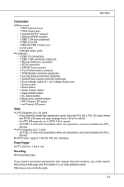
... Combo port - 2 LAN ports - 6 flexible audio ports ■ On-Board - 3 USB 2.0 connectors - 1 IEEE 1394 connector (optional) - 1 Chassis Intrusion connector - 1 CD-In connector - 1 S/PDIF-Out connector - 1 Front Panel Audio connector - 1 TPM Module connector (optional) - 1 D-LED2 panel connector (optional) - 1 GreenPower Genie connector (optional) - 1 Over-Voltage switch & 1 set voltage check point - 1 Power button - 1 Reset button - 1 Green Power button - 1 Clear CMOS button - 1 OC Genie button - 2 Base clock control buttons - 1 CPU Phase LED panel - 1 set Debug LED panel Slots ■ 3 PCI...
... Combo port - 2 LAN ports - 6 flexible audio ports ■ On-Board - 3 USB 2.0 connectors - 1 IEEE 1394 connector (optional) - 1 Chassis Intrusion connector - 1 CD-In connector - 1 S/PDIF-Out connector - 1 Front Panel Audio connector - 1 TPM Module connector (optional) - 1 D-LED2 panel connector (optional) - 1 GreenPower Genie connector (optional) - 1 Over-Voltage switch & 1 set voltage check point - 1 Power button - 1 Reset button - 1 Green Power button - 1 Clear CMOS button - 1 OC Genie button - 2 Base clock control buttons - 1 CPU Phase LED panel - 1 set Debug LED panel Slots ■ 3 PCI...

User Guide
Page 36
... configuration to set the computer's function. OC Genie Button: OC Genie This button is in power off the system before clearing CMOS data. Important Please install the DDR3 1333 and up memory and equip better heat sink/ cooler with OC Genie function. ▍ Hardware Setup Button The motherboard provides the following buttons for you to overclocking profile in BIOS for future using. 2-20 This section will boot...
... configuration to set the computer's function. OC Genie Button: OC Genie This button is in power off the system before clearing CMOS data. Important Please install the DDR3 1333 and up memory and equip better heat sink/ cooler with OC Genie function. ▍ Hardware Setup Button The motherboard provides the following buttons for you to overclocking profile in BIOS for future using. 2-20 This section will boot...

User Guide
Page 40
Meanwhile, read the documentation for the expansion card to configure any necessary hardware or software settings for the expansion card, such as jumpers, switches or BIOS configuration. ▍ Hardware Setup Slots PCIE (Peripheral Component Interconnect Express) Slot The PCI Express slot supports the PCI Express interface expansion card. The PCI Express x1 slots will unavailable when an expansion card was installed into PCI_E5 slot. 2-24 PCI Express x16 Slot PCI Express x1 Slot Important When adding or removing expansion cards, make sure that you unplug the power supply first.
Meanwhile, read the documentation for the expansion card to configure any necessary hardware or software settings for the expansion card, such as jumpers, switches or BIOS configuration. ▍ Hardware Setup Slots PCIE (Peripheral Component Interconnect Express) Slot The PCI Express slot supports the PCI Express interface expansion card. The PCI Express x1 slots will unavailable when an expansion card was installed into PCI_E5 slot. 2-24 PCI Express x16 Slot PCI Express x1 Slot Important When adding or removing expansion cards, make sure that you unplug the power supply first.
User Guide
Page 41
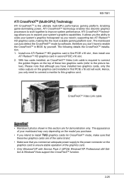
... CrossFireXTM installation. 1. Hence, you need to connect a monitor to this graphics card. Enabling game-dominating power, ATI CrossFireXTM technology enables two discrete graphics processors to work . With two cards installed, an CrossFireXTM Video Link cable is the ultimate multi-GPU performance gaming platform. The appearance of your mainboard may vary depending on the graphics card to ensure stable operation of the graphics card. • Only Windows®XP with Service Pack 2 (SP2)& Windows®...
... CrossFireXTM installation. 1. Hence, you need to connect a monitor to this graphics card. Enabling game-dominating power, ATI CrossFireXTM technology enables two discrete graphics processors to work . With two cards installed, an CrossFireXTM Video Link cable is the ultimate multi-GPU performance gaming platform. The appearance of your mainboard may vary depending on the graphics card to ensure stable operation of the graphics card. • Only Windows®XP with Service Pack 2 (SP2)& Windows®...
User Guide
Page 45
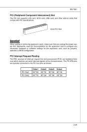
... interrupt signals to the PCI bus pins as jumpers, switches or BIOS configuration. MS-7581 PCI (Peripheral Component Interconnect) Slot The PCI slot supports LAN card, SCSI card, USB card, and other add-on cards that comply with PCI specifications. 32-bit PCI Slot Important When adding or removing expansion cards, make sure that you unplug the power supply first. PCI Interrupt Request Routing The IRQ, acronym of interrupt request line and pronounced I-R-Q, are typically connected to the microprocessor.
... interrupt signals to the PCI bus pins as jumpers, switches or BIOS configuration. MS-7581 PCI (Peripheral Component Interconnect) Slot The PCI slot supports LAN card, SCSI card, USB card, and other add-on cards that comply with PCI specifications. 32-bit PCI Slot Important When adding or removing expansion cards, make sure that you unplug the power supply first. PCI Interrupt Request Routing The IRQ, acronym of interrupt request line and pronounced I-R-Q, are typically connected to the microprocessor.

User Guide
Page 48
... chipset registers. Display the system configuration screen if enabled. Enter OS (Vista or Windows® XP). 2-32 Initialize chipset. Initialize USB device and different devices. BIOS setup if needed . Post FF C0, C1, C2 C4, C6 D4, D5 08 2A, 31 37 38 3C 75, 78 87 A4 A7 B1 00 AA Status Power on message, CPU information, setup key message and any OEM specific information. Initialize keyboard. Load Option ROM (VGA and RAID option ROM) form BIOS...
... chipset registers. Display the system configuration screen if enabled. Enter OS (Vista or Windows® XP). 2-32 Initialize chipset. Initialize USB device and different devices. BIOS setup if needed . Post FF C0, C1, C2 C4, C6 D4, D5 08 2A, 31 37 38 3C 75, 78 87 A4 A7 B1 00 AA Status Power on message, CPU information, setup key message and any OEM specific information. Initialize keyboard. Load Option ROM (VGA and RAID option ROM) form BIOS...

User Guide
Page 56
... viruses. ▶ Full Screen Logo Display This item enables this function at boot. 3-8 The only time when you to set the first/ second/ third boot device where BIOS attempts to load the disk operating system. ▶ Boot From Other Device Setting the option to [Yes] allows the system to try to boot from other device, if the system fails to update the BIOS with a Flash utility. Settings are: [Enabled] Shows a still image...
... viruses. ▶ Full Screen Logo Display This item enables this function at boot. 3-8 The only time when you to set the first/ second/ third boot device where BIOS attempts to load the disk operating system. ▶ Boot From Other Device Setting the option to [Yes] allows the system to try to boot from other device, if the system fails to update the BIOS with a Flash utility. Settings are: [Enabled] Shows a still image...

User Guide
Page 57
... the system is part of your operating system. ▶ Primary Graphic's Adapter This setting specifies which MPS (Multi-Processor Specification) version to be used to enable or disable the APIC (Advanced Programmable Interrupt Controller). Setting to [Off] will skip some check items. ▶ Boot Up Num-Lock LED This setting is to set the item to higher values. ▶ HPET The HPET (High Precision Event Timers...
... the system is part of your operating system. ▶ Primary Graphic's Adapter This setting specifies which MPS (Multi-Processor Specification) version to be used to enable or disable the APIC (Advanced Programmable Interrupt Controller). Setting to [Off] will skip some check items. ▶ Boot Up Num-Lock LED This setting is to set the item to higher values. ▶ HPET The HPET (High Precision Event Timers...
User Guide
Page 58
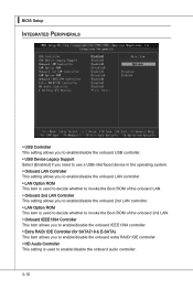
... the Boot ROM of the onboard LAN. ▶ Onboard 2nd LAN Controller This setting allows you to enable/disable the onboard 2nd LAN controller. ▶ LAN Option ROM This item is used to decide whether to invoke the Boot ROM of the onboard 2nd LAN. ▶ Onboard IEEE1394 Controller This item allows you to enable/disable the onboard IEEE1394 controller. ▶ Extra RAID/ IDE Controller (for SATA7/ 8 & E-SATA) This item allows you to enable/disable the onboard extra RAID/ IDE controller. ▶ HD Audio Controller This setting is used to enable/disable the onboard audio controller...
... the Boot ROM of the onboard LAN. ▶ Onboard 2nd LAN Controller This setting allows you to enable/disable the onboard 2nd LAN controller. ▶ LAN Option ROM This item is used to decide whether to invoke the Boot ROM of the onboard 2nd LAN. ▶ Onboard IEEE1394 Controller This item allows you to enable/disable the onboard IEEE1394 controller. ▶ Extra RAID/ IDE Controller (for SATA7/ 8 & E-SATA) This item allows you to enable/disable the onboard extra RAID/ IDE controller. ▶ HD Audio Controller This setting is used to enable/disable the onboard audio controller...

User Guide
Page 60
... your operating system supports ACPI, such as Windows 98SE/ 2000/ ME/ XP, select [Enabled]. ▶ ACPI Standby State This item specifies the power saving modes for ACPI function. The information stored in memory will be used to enter the Standby mode in S1(POS) or S3(STR) fashion through the setting of system configuration and open applications/files is ACPI-aware, such as Windows 2000/ XP, you...
... your operating system supports ACPI, such as Windows 98SE/ 2000/ ME/ XP, select [Enabled]. ▶ ACPI Standby State This item specifies the power saving modes for ACPI function. The information stored in memory will be used to enter the Standby mode in S1(POS) or S3(STR) fashion through the setting of system configuration and open applications/files is ACPI-aware, such as Windows 2000/ XP, you...

User Guide
Page 61
... S3 By PS/2 Keyboard / Mouse These items determine whether the system will be awakened from what power saving modes when input signal of the USB device to wake up events. This item configures how the system uses power LED on PME (Power Management Event). 3-13 MS-7581 ▶ Power LED When ACPI Standby State is detected. ▶ Resume By PCI Device (PME#) When set to [S3], this...
... S3 By PS/2 Keyboard / Mouse These items determine whether the system will be awakened from what power saving modes when input signal of the USB device to wake up events. This item configures how the system uses power LED on PME (Power Management Event). 3-13 MS-7581 ▶ Power LED When ACPI Standby State is detected. ▶ Resume By PCI Device (PME#) When set to [S3], this...

User Guide
Page 63
... return to [Enabled] later. ▶ CPU Smart FAN Target The mainboard provides the Smart Fan function which can enable a fan target value here. You can control the CPU fan speed automatically depending on the current temperature to [Reset]. It provides several sections to speed up for cooling down automatically. ▶ CPU Min.FAN Speed(%) This item allows users to select the percentage of speed for the SYSFAN1/ 2. 3-15 To clear the warning...
... return to [Enabled] later. ▶ CPU Smart FAN Target The mainboard provides the Smart Fan function which can enable a fan target value here. You can control the CPU fan speed automatically depending on the current temperature to [Reset]. It provides several sections to speed up for cooling down automatically. ▶ CPU Min.FAN Speed(%) This item allows users to select the percentage of speed for the SYSFAN1/ 2. 3-15 To clear the warning...
User Guide
Page 73
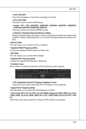
Setting to [Manual] allows you to set the following screen appears. ▶ CPU Amplitude Control/ PCI Express Amplitude Control These items are used to select the CPU/ PCI Express clock amplitude. ▶ Adjust PCI-E Frequency (MHz) This field allows you to select the PCIE frequency (in MHz). ▶ CPU VCore/ CPU VTT (V)/ PCH 1.8V (V)/ DRAM Voltage (V)/ DDR_VREF_CA_A (V)/ / DDR_VREF_CA_B (V)/ DDR_VREF_DA_A (V)/ / DDR_VREF_DA_B (V)/ PCH 1.05V (V) These items are used to set the tFAW timing. ▶ Current CH1/ CH2...
Setting to [Manual] allows you to set the following screen appears. ▶ CPU Amplitude Control/ PCI Express Amplitude Control These items are used to select the CPU/ PCI Express clock amplitude. ▶ Adjust PCI-E Frequency (MHz) This field allows you to select the PCIE frequency (in MHz). ▶ CPU VCore/ CPU VTT (V)/ PCH 1.8V (V)/ DRAM Voltage (V)/ DDR_VREF_CA_A (V)/ / DDR_VREF_CA_B (V)/ DDR_VREF_DA_A (V)/ / DDR_VREF_DA_B (V)/ PCH 1.05V (V) These items are used to set the tFAW timing. ▶ Current CH1/ CH2...

User Guide
Page 78
... only supports FAT/ FAT32 file system drive. ▶ Save File Name as sets to [Boot] or [BIOS Update], this item is selectable. Note: we suggest you using [ROM] as Please setup a specific extend name for the BIOS file, which will be saved into the USB drive/ storage drive. Note: we suggest you using the official name as the default name. ▶ Save Extend File name as default name. ▶ Start to save the onboard ROM chip...
... only supports FAT/ FAT32 file system drive. ▶ Save File Name as sets to [Boot] or [BIOS Update], this item is selectable. Note: we suggest you using [ROM] as Please setup a specific extend name for the BIOS file, which will be saved into the USB drive/ storage drive. Note: we suggest you using the official name as the default name. ▶ Save Extend File name as default name. ▶ Start to save the onboard ROM chip...

User Guide
Page 114
... uses long, thin cables, making it easier to connect your drive and improving the airflow inside your system might differ from a designated Master drive to separate hard drives. And the least number of Mirrors) , Intel® Martix Storage Technology and Intel® Rapid Recover Technology. The most popular implementations of the Recovery drive. ▍ Intel SATA RAID Introduction The mainboard comes with CRC error checking. 2. Intel® RAID controller...
... uses long, thin cables, making it easier to connect your drive and improving the airflow inside your system might differ from a designated Master drive to separate hard drives. And the least number of Mirrors) , Intel® Martix Storage Technology and Intel® Rapid Recover Technology. The most popular implementations of the Recovery drive. ▍ Intel SATA RAID Introduction The mainboard comes with CRC error checking. 2. Intel® RAID controller...

User Guide
Page 115
... DOS disk services. Please use + keys to enter the "Intel® RAID for a few seconds: Important The "Drvice Model", "Serial #" and "Size" in BIOS to create, delete and reset RAID volumes. MS-7581 BIOS Configuration The Intel Matrix Storage Manager Option ROM should not be used to migrate an existing system to RAID. Important The following example might be configured using the RAID Configuration utility stored within the Intel RAID Option ROM. The Intel Matrix Stroage Manager Option ROM...
... DOS disk services. Please use + keys to enter the "Intel® RAID for a few seconds: Important The "Drvice Model", "Serial #" and "Size" in BIOS to create, delete and reset RAID volumes. MS-7581 BIOS Configuration The Intel Matrix Storage Manager Option ROM should not be used to migrate an existing system to RAID. Important The following example might be configured using the RAID Configuration utility stored within the Intel RAID Option ROM. The Intel Matrix Stroage Manager Option ROM...
User Guide
Page 122
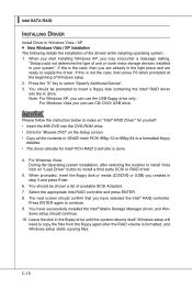
... press Enter. 6. Press the "S" key to continue. 9. Note: For Windows XP, you can use CD/ DVD/ USB drive. Windows setup will need to supply the driver. For Windows Vista you can use the USB floppy drive only. You should be shown a list of Windows setup. 2. When you start installing Windows XP, you are already in the right place and are ready to copy the files from the floppy again after selecting the location to install Vista...
... press Enter. 6. Press the "S" key to continue. 9. Note: For Windows XP, you can use CD/ DVD/ USB drive. Windows setup will need to supply the driver. For Windows Vista you can use the USB floppy drive only. You should be shown a list of Windows setup. 2. When you start installing Windows XP, you are already in the right place and are ready to copy the files from the floppy again after selecting the location to install Vista...


