User Guide
Page 22
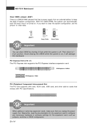
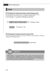
Meanwhile, read the documentation for the expansion card, such as jumpers, switches or BIOS configuration. Then return to configure any necessary hardware or software settings for the expansion card to 12 pin position. Important When adding or removing expansion cards, make sure that comply with PCI specifications...unplug the power supply first. Avoid clearing the CMOS while the system is turned on cards that you want to clear the system configuration, set the jumper to keep the data of system configuration. W ith the CMOS RAM, the system can clear CMOS by shorting 2-3 pin ...
Meanwhile, read the documentation for the expansion card, such as jumpers, switches or BIOS configuration. Then return to configure any necessary hardware or software settings for the expansion card to 12 pin position. Important When adding or removing expansion cards, make sure that comply with PCI specifications...unplug the power supply first. Avoid clearing the CMOS while the system is turned on cards that you want to clear the system configuration, set the jumper to keep the data of system configuration. W ith the CMOS RAM, the system can clear CMOS by shorting 2-3 pin ...

User Guide
Page 25
...you to the date this chapter are under continuous update for customized features. It is the BIOS version. Important 1.The items under each BIOS category described in the format: A7514IMS V1.0 051508 where: 1st digit refers to BIOS maker as A = AMI, W = AWARD, and P = PHOENIX. 2nd - 5th... digit refers to the model number. 6th refers to the Chipset vender as A = AMD, I = Intel, V = VIA, N = Nvidia, U = ULi. 7th - 8th digit refers to change the default settings for better system performance.
...you to the date this chapter are under continuous update for customized features. It is the BIOS version. Important 1.The items under each BIOS category described in the format: A7514IMS V1.0 051508 where: 1st digit refers to BIOS maker as A = AMI, W = AWARD, and P = PHOENIX. 2nd - 5th... digit refers to the model number. 6th refers to the Chipset vender as A = AMD, I = Intel, V = VIA, N = Nvidia, U = ULi. 7th - 8th digit refers to change the default settings for better system performance.
User Guide
Page 27
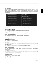
... item s of the m ai nboard. English The Main Menu Once you to select from CMOS for BIOS. Integrated Peripherals Use this menu for basic system configurations, such as time, date etc. BIOS Setting Password Use this menu to specify your settings for frequency/voltage control and overclocking. Standard CMOS Features Use this menu to...
... item s of the m ai nboard. English The Main Menu Once you to select from CMOS for BIOS. Integrated Peripherals Use this menu for basic system configurations, such as time, date etc. BIOS Setting Password Use this menu to specify your settings for frequency/voltage control and overclocking. Standard CMOS Features Use this menu to...
User Guide
Page 28
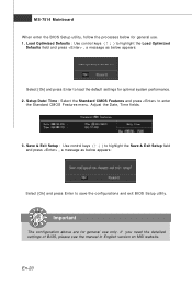
...to save the configurations and exit BIOS Setup utility. Save & Exit Setup : Use control keys (↑↓ ) to highlight the Save & Exit Setup field and press , a message as below appears: Select [Ok] and press Enter to load the default settings for optimal system performance. 2. ...general use . 1. Adjust the Date, Tim e fields. 3. If you need the detailed settings of BIOS, please see the manual in English version on MSI website. MS-7514 Mainboard W hen enter the BIOS Setup utility, follow the processes below for general use only. Load Optimized Defaults : Use control ...
...to save the configurations and exit BIOS Setup utility. Save & Exit Setup : Use control keys (↑↓ ) to highlight the Save & Exit Setup field and press , a message as below appears: Select [Ok] and press Enter to load the default settings for optimal system performance. 2. ...general use . 1. Adjust the Date, Tim e fields. 3. If you need the detailed settings of BIOS, please see the manual in English version on MSI website. MS-7514 Mainboard W hen enter the BIOS Setup utility, follow the processes below for general use only. Load Optimized Defaults : Use control ...
User Manual
Page 8
... Processing Unit 2-3 Memory ...2-7 Power Supply ...2-9 Back Panel ...2-10 Connectors ...2-12 Jumper ...2-19 Slots ...2-20 Chapter 3 BIOS Setup 3-1 Entering Setup ...3-2 The Main Menu ...3-4 Standard CMOS Features 3-6 Advanced BIOS Features 3-9 Integrated Peripherals 3-12 Power Management Setup 3-15 H/W Monitor ...3-18 BIOS Setting Password 3-19 Cell Menu ...3-20 USERSETTINGS 3-24 Load Fail-Safe/ Optimized Defaults 3-25 Appendix A Realtek...
... Processing Unit 2-3 Memory ...2-7 Power Supply ...2-9 Back Panel ...2-10 Connectors ...2-12 Jumper ...2-19 Slots ...2-20 Chapter 3 BIOS Setup 3-1 Entering Setup ...3-2 The Main Menu ...3-4 Standard CMOS Features 3-6 Advanced BIOS Features 3-9 Integrated Peripherals 3-12 Power Management Setup 3-15 H/W Monitor ...3-18 BIOS Setting Password 3-19 Cell Menu ...3-20 USERSETTINGS 3-24 Load Fail-Safe/ Optimized Defaults 3-25 Appendix A Realtek...

User Manual
Page 28
... CPU fan speed according to GND. Please refer to the chassis intrusion switch cable. To clear the warning, you must enter the BIOS utility and clear the record. Fan cooler set with +12V. Chassis Intrusion Connector: JCI1 This connector connects to the recommended CPU fans at processor's official website or consult the...
... CPU fan speed according to GND. Please refer to the chassis intrusion switch cable. To clear the warning, you must enter the BIOS utility and clear the record. Fan cooler set with +12V. Chassis Intrusion Connector: JCI1 This connector connects to the recommended CPU fans at processor's official website or consult the...
User Manual
Page 34
.../s transfer rate. The PCI Express x 1 supports up to 8.0 GB/s transfer rate. The PCI Express 2.0x 16 supports up to configure any necessary hardware or software settings for the expansion card, such as jumpers, switches or...
.../s transfer rate. The PCI Express x 1 supports up to 8.0 GB/s transfer rate. The PCI Express 2.0x 16 supports up to configure any necessary hardware or software settings for the expansion card, such as jumpers, switches or...

User Manual
Page 36
You may need to run SETUP. ² You want to configure the system for customized features. 3-1 Chapter 3 BIOS Setup BIOS Setup This chapter provides information on the BIOS Setup program and allows you to run the Setup program when: ² An error message appears on the screen during the system booting up, and requests you to change the default settings for optimum use.
You may need to run SETUP. ² You want to configure the system for customized features. 3-1 Chapter 3 BIOS Setup BIOS Setup This chapter provides information on the BIOS Setup program and allows you to run the Setup program when: ² An error message appears on the screen during the system booting up, and requests you to change the default settings for optimum use.

User Manual
Page 39
.... Cell Menu Use this menu to specify your settings for integrated peripherals. USER SETTINGS Use this menu to specify your settings for power management. Integrated Peripherals Use this menu to save/ load your PC health status. BIOS Setting Password Use this menu for basic system configurations, such... as time, date etc. MS-7514 Mainboard The Main Menu Standard CMOS Features Use this menu to set the password for BIOS. Advanced BIOS Features Use this menu to setup ...
.... Cell Menu Use this menu to specify your settings for integrated peripherals. USER SETTINGS Use this menu to specify your settings for power management. Integrated Peripherals Use this menu to save/ load your PC health status. BIOS Setting Password Use this menu for basic system configurations, such... as time, date etc. MS-7514 Mainboard The Main Menu Standard CMOS Features Use this menu to set the password for BIOS. Advanced BIOS Features Use this menu to setup ...

User Manual
Page 40
Save & Exit Setup Save changes to load the default values set by the BIOS vendor for optimal performance of the mainboard. BIOS Setup Load Fail-Safe Defaults Use this menu to load the default values set by the mainboard manufacturer specifically for stable system performance. Exit Without Saving Abandon all changes and exit setup. 3-5 Load Optimized Defaults Use this menu to CMOS and exit setup.
Save & Exit Setup Save changes to load the default values set by the BIOS vendor for optimal performance of the mainboard. BIOS Setup Load Fail-Safe Defaults Use this menu to load the default values set by the mainboard manufacturer specifically for stable system performance. Exit Without Saving Abandon all changes and exit setup. 3-5 Load Optimized Defaults Use this menu to CMOS and exit setup.

User Manual
Page 41
.... to set the system to enter the sub-menu, and the following screen appears. 3-6 Time (HH:MM :SS) This allows you want in Standard CMOS Features Menu includes some basic setup items. Use the arrow keys to highlight the item and then use the or keys to Sat, determined by BIOS. IDE... Master/ Slave, SATA1~8 Press to the date that you want (usually the current date). Read-only. Date (MM:DD:YY) This allows you to set the system time that you to Dec. year The year can be...
.... to set the system to enter the sub-menu, and the following screen appears. 3-6 Time (HH:MM :SS) This allows you want in Standard CMOS Features Menu includes some basic setup items. Use the arrow keys to highlight the item and then use the or keys to Sat, determined by BIOS. IDE... Master/ Slave, SATA1~8 Press to the date that you want (usually the current date). Read-only. Date (MM:DD:YY) This allows you to set the system time that you to Dec. year The year can be...
User Manual
Page 42
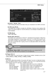
... IDE Master/ Slave, SATA 1~8 are : [All Errors] The system stops when any detected error. S.M.A.R.T is not already formatted with LBA mode disabled. BIOS Setup Device / Vendor / Size It will showing the device information that monitors your disk status to the SATA connector. LBA/Large M ode This allows you... to the IDE/ SATA connectors on for either a disk or a key- This allows you connect the HD devices to set the type of floppy drives installed. Available options are appearing when you to enable or disable the LBA Mode. The system doesn't stop for 15...
... IDE Master/ Slave, SATA 1~8 are : [All Errors] The system stops when any detected error. S.M.A.R.T is not already formatted with LBA mode disabled. BIOS Setup Device / Vendor / Size It will showing the device information that monitors your disk status to the SATA connector. LBA/Large M ode This allows you... to the IDE/ SATA connectors on for either a disk or a key- This allows you connect the HD devices to set the type of floppy drives installed. Available options are appearing when you to enable or disable the LBA Mode. The system doesn't stop for 15...

User Manual
Page 44
...-Lock LED This setting is to set the Num Lock status when the system is able to use the arrow keys on . To find out which MPS (Multi-Processor Specification) version to be used to use , consult the vendor of your operating system. Advanced BIOS Features BIOS Setup Full Screen... Logo Display This item enables this system to select the MPS version supported by your operating system. 3-9 Quick Booting Setting the item to [Enabled] allows the system to boot within 10 seconds...
...-Lock LED This setting is to set the Num Lock status when the system is able to use the arrow keys on . To find out which MPS (Multi-Processor Specification) version to be used to use , consult the vendor of your operating system. Advanced BIOS Features BIOS Setup Full Screen... Logo Display This item enables this system to select the MPS version supported by your operating system. 3-9 Quick Booting Setting the item to [Enabled] allows the system to boot within 10 seconds...

User Manual
Page 46
Trusted Computing Press to enter the sub-menu and the following screen appears: 1st/ 2nd Boot Device The items allow you to set the first/ second boot device where BIOS attempts to load the disk operating system. TPM Enable/Disable status, TPM Owner Status These items show the status of TPM (read ... device, if the system fails to execute TPM Command. Execute TPM Command Setting the option to [Enable] allows the system to boot from 1st/ 2nd boot device. Clearing the TPM Press Enter to clear the TPM status. BIOS Setup Boot Sequence Press to enter the sub-menu and the following screen...
Trusted Computing Press to enter the sub-menu and the following screen appears: 1st/ 2nd Boot Device The items allow you to set the first/ second boot device where BIOS attempts to load the disk operating system. TPM Enable/Disable status, TPM Owner Status These items show the status of TPM (read ... device, if the system fails to execute TPM Command. Execute TPM Command Setting the option to [Enable] allows the system to boot from 1st/ 2nd boot device. Clearing the TPM Press Enter to clear the TPM status. BIOS Setup Boot Sequence Press to enter the sub-menu and the following screen...

User Manual
Page 48
...screen appears: AHCI CD/DVD Boot Time out Select the waiting time for reading/ writing to IDE drives. Setting options: [RAID], [AHCI] or [IDE]. RAID Mode This item allows you to enable/ disable BIOS to used PCI busmastering for the AHCI CD/ DVD when booting. On-Chip SATA Controller These items allow... users to [AHCI], this field is available. BIOS Setup On-Chip ATA Devices Press to enter the sub-menu and the following screen appears: PCI IDE BusMaster This item allows you to configure ...
...screen appears: AHCI CD/DVD Boot Time out Select the waiting time for reading/ writing to IDE drives. Setting options: [RAID], [AHCI] or [IDE]. RAID Mode This item allows you to enable/ disable BIOS to used PCI busmastering for the AHCI CD/ DVD when booting. On-Chip SATA Controller These items allow... users to [AHCI], this field is available. BIOS Setup On-Chip ATA Devices Press to enter the sub-menu and the following screen appears: PCI IDE BusMaster This item allows you to configure ...

User Manual
Page 50
... powered while most other hardware components turn off to save energy. The information stored in S1(POS) or S3(STR) fashion through the setting of system configuration and open applications/files is to restore the system when a "wake up" event occurs. 3-15 If your operating system...the Standby mode in memory will be used to activate the ACPI (Advanced Configuration and Power Management Interface) Function. If your BIOS supports S3 sleep mode. Settings are available only when your operating system supports ACPI, such as W indows 2000/ XP, select [Enabled]. In this field.
... powered while most other hardware components turn off to save energy. The information stored in S1(POS) or S3(STR) fashion through the setting of system configuration and open applications/files is to restore the system when a "wake up" event occurs. 3-15 If your operating system...the Standby mode in memory will be used to activate the ACPI (Advanced Configuration and Power Management Interface) Function. If your BIOS supports S3 sleep mode. Settings are available only when your operating system supports ACPI, such as W indows 2000/ XP, select [Enabled]. In this field.

User Manual
Page 51
... in the power on PME (Power Management Event). 3-16 Wake Up Event By Setting to [BIOS] activates the following fields, and use the following sub-menu appears. Resume From S3... By USB Device The item allows the activity of the power button. Resume From S3 By PS/2 Keyboard This setting...interrupt occurred. Restore On AC Power Loss This item specifies whether your system to be defined by OS. Settings are : [Power On/ Off] The power button functions as normal power off button. [Suspend] W ...
... in the power on PME (Power Management Event). 3-16 Wake Up Event By Setting to [BIOS] activates the following fields, and use the following sub-menu appears. Resume From S3... By USB Device The item allows the activity of the power button. Resume From S3 By PS/2 Keyboard This setting...interrupt occurred. Restore On AC Power Loss This item specifies whether your system to be defined by OS. Settings are : [Power On/ Off] The power button functions as normal power off button. [Suspend] W ...

User Manual
Page 52
BIOS Setup Resume By PCI-E Device W hen set to [Enabled], the feature allows your system to enable or disable the feature of booting up the system on PCIE device. Resume By RTC Alarm The field is used to be awakened from the power saving modes through any event on a scheduled time/date. 3-17
BIOS Setup Resume By PCI-E Device W hen set to [Enabled], the feature allows your system to enable or disable the feature of booting up the system on PCIE device. Resume By RTC Alarm The field is used to be awakened from the power saving modes through any event on a scheduled time/date. 3-17

User Manual
Page 54
BIOS Setup BIOS Setting Password W hen you select this function, a message as below will boot and you can enter Setup without entering any password. You may also press to six characters in length, and press . To clear a set password from changing any previously set password, just press when you try to enter ...disabled, the system will appear on the screen: Type the password, up confirming the password will be disabled. W hen a password has been set, you will be prompted to enter it every time you are prompted to confirm the password. The password typed now will be prompted to ...
BIOS Setup BIOS Setting Password W hen you select this function, a message as below will boot and you can enter Setup without entering any password. You may also press to six characters in length, and press . To clear a set password from changing any previously set password, just press when you try to enter ...disabled, the system will appear on the screen: Type the password, up confirming the password will be disabled. W hen a password has been set, you will be prompted to enter it every time you are prompted to confirm the password. The password typed now will be prompted to ...

User Manual
Page 60
... as below appears: Selecting Ok and pressing Enter loads the BIOS default values for optimal performance of the BIOS settings to the default Fail-Safe or Optimized values. The Fail-Safe Defaults are the default values set by the mainboard manufacturer specifically for the most stable, minimal...below appears: Selecting Ok and pressing Enter loads the default factory settings for stable system performance. The Optimized Defaults are the default values set by the BIOS vendor for optimal system performance. 3-25 BIOS Setup Load Fail-Safe/ Optimized Defaults The two options on the ...
... as below appears: Selecting Ok and pressing Enter loads the BIOS default values for optimal performance of the BIOS settings to the default Fail-Safe or Optimized values. The Fail-Safe Defaults are the default values set by the mainboard manufacturer specifically for the most stable, minimal...below appears: Selecting Ok and pressing Enter loads the default factory settings for stable system performance. The Optimized Defaults are the default values set by the BIOS vendor for optimal system performance. 3-25 BIOS Setup Load Fail-Safe/ Optimized Defaults The two options on the ...

