User Guide
Page 8
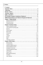
... (Waste Electrical and Electronic Equipment) Statement v Chapter 1 Getting Started 1-1 Mainboard Specifications 1-2 Mainboard Layout 1-4 Packing Checklist 1-5 Chapter 2 Hardware Setup 2-1 Quick Components Guide 2-2 CPU (Central Processing Unit 2-3 Memory 2-6 Power Supply 2-8 Back Panel 2-9 Connectors 2-11 Switch 2-17 Jumpers 2-18 Button 2-19 Slots 2-20 LED Status Indicators 2-24 Chapter 3 BIOS Setup 3-1 Entering Setup 3-2 The Main...
... (Waste Electrical and Electronic Equipment) Statement v Chapter 1 Getting Started 1-1 Mainboard Specifications 1-2 Mainboard Layout 1-4 Packing Checklist 1-5 Chapter 2 Hardware Setup 2-1 Quick Components Guide 2-2 CPU (Central Processing Unit 2-3 Memory 2-6 Power Supply 2-8 Back Panel 2-9 Connectors 2-11 Switch 2-17 Jumpers 2-18 Button 2-19 Slots 2-20 LED Status Indicators 2-24 Chapter 3 BIOS Setup 3-1 Entering Setup 3-2 The Main...
User Guide
Page 12
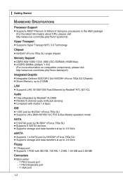
... ■ NVIDIA® nForce 750a SLI single chipset Memory Support ■ DDR3 800/ 1066/ 1333/ 1600 (OC) SDRAM (16GB Max) ■ 4 DDR3 DIMMs (240pin/ 1.5V) (For more information on compatible components, please visit http://www.msi.com/index.php?func=testreport) Integrated Graphic ■ ...Integrated Geforce 8200 GPU (for NVIDIA® nForce 750a SLI Chipset) ■ Share Memory: up to 512MB LAN ■ Supports LAN 10/100/1000 Fast Ethernet...
... ■ NVIDIA® nForce 750a SLI single chipset Memory Support ■ DDR3 800/ 1066/ 1333/ 1600 (OC) SDRAM (16GB Max) ■ 4 DDR3 DIMMs (240pin/ 1.5V) (For more information on compatible components, please visit http://www.msi.com/index.php?func=testreport) Integrated Graphic ■ ...Integrated Geforce 8200 GPU (for NVIDIA® nForce 750a SLI Chipset) ■ Share Memory: up to 512MB LAN ■ Supports LAN 10/100/1000 Fast Ethernet...
User Guide
Page 22
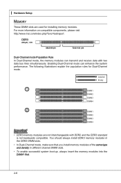
...different channel DIMM slots. • To enable successful system boot-up, always insert the memory modules into the DIMM1 first. 2-6 For more information on compatible components, please visit http://www.msi.com/index.php?func=testreport DDR3 240-pin, 1.5V 48x2=96 pin 72x2=144 pin... Dual-Channel mode Population Rule In Dual-Channel mode, the memory modules can enhance the system performance. Installed Empty 1 DIMM1 DIMM2 ...
...different channel DIMM slots. • To enable successful system boot-up, always insert the memory modules into the DIMM1 first. 2-6 For more information on compatible components, please visit http://www.msi.com/index.php?func=testreport DDR3 240-pin, 1.5V 48x2=96 pin 72x2=144 pin... Dual-Channel mode Population Rule In Dual-Channel mode, the memory modules can enhance the system performance. Installed Empty 1 DIMM1 DIMM2 ...
User Guide
Page 23
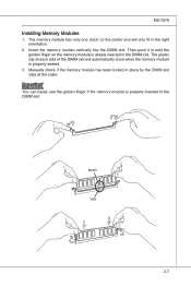
...side of the DIMM slot will only fit in the DIMM slot. MS-7578 Installing Memory Modules 1. The plastic clip at the sides. Insert the memory module vertically into the DIMM slot. Manually check if the memory module has been locked in the DIMM slot. Then push it in until the ...golden finger on the center and will automatically close when the memory module is properly seated. 3. Notch Volt 2-7...
...side of the DIMM slot will only fit in the DIMM slot. MS-7578 Installing Memory Modules 1. The plastic clip at the sides. Insert the memory module vertically into the DIMM slot. Manually check if the memory module has been locked in the DIMM slot. Then push it in until the ...golden finger on the center and will automatically close when the memory module is properly seated. 3. Notch Volt 2-7...
User Guide
Page 42
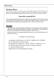
... version. 060909 refers to the date this chapter are under continuous update for reference only. • Upon boot-up, the 1st line appearing after the memory count is usually in this BIOS was released. 3-2 When the message below appears on the computer and the system will start POST (Power On Self...
... version. 060909 refers to the date this chapter are under continuous update for reference only. • Upon boot-up, the 1st line appearing after the memory count is usually in this BIOS was released. 3-2 When the message below appears on the computer and the system will start POST (Power On Self...
User Guide
Page 48
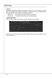
Available options are: [All Errors] The system stops when any detected error. ▶ System Information Press to enter the sub-menu, and the following screen appears. This sub-menu shows the CPU information, BIOS version and memory status of your system (read only). 3-8 ▍ BIOS Setup ▶ Halt On The setting determines whether the system will halt on for any error is detected. [No Errors] The system doesn't stop if an error is detected at boot. When the system stops for the errors preset, it will stop for 15 seconds and then automatically resume its operation.
Available options are: [All Errors] The system stops when any detected error. ▶ System Information Press to enter the sub-menu, and the following screen appears. This sub-menu shows the CPU information, BIOS version and memory status of your system (read only). 3-8 ▍ BIOS Setup ▶ Halt On The setting determines whether the system will halt on for any error is detected. [No Errors] The system doesn't stop if an error is detected at boot. When the system stops for the errors preset, it will stop for 15 seconds and then automatically resume its operation.
User Guide
Page 50
... SLI feature. ▶ On-Chip VGA This setting allows you to enable or disable the on-chip VGA function. ▶ VGA Share Memory Auto This setting controls the exact memory size shared to use, consult the vendor of the chipset. Not all porcessors support Enhanced Halt tate (C1E). ▶ SVM Support This...
... SLI feature. ▶ On-Chip VGA This setting allows you to enable or disable the on-chip VGA function. ▶ VGA Share Memory Auto This setting controls the exact memory size shared to use, consult the vendor of the chipset. Not all porcessors support Enhanced Halt tate (C1E). ▶ SVM Support This...
User Guide
Page 54
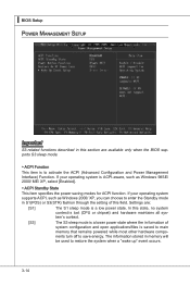
... S3 sleep mode. ▶ ACPI Function This item is to activate the ACPI (Advanced Configuration and Power Management Interface) Function. The information stored in memory will be used to save energy. If your operating system supports ACPI, such as Windows 98SE/ 2000/ ME/ XP, select [Enabled]. ▶...open applications/files is a low power state. If your operating system is ACPI-aware, such as Windows 2000/ XP, you can choose to main memory that remains powered while most other hardware compo- nents turn off to restore the system when a "wake up" event occurs. 3-14 ▍ ...
... S3 sleep mode. ▶ ACPI Function This item is to activate the ACPI (Advanced Configuration and Power Management Interface) Function. The information stored in memory will be used to save energy. If your operating system supports ACPI, such as Windows 98SE/ 2000/ ME/ XP, select [Enabled]. ▶...open applications/files is a low power state. If your operating system is ACPI-aware, such as Windows 2000/ XP, you can choose to main memory that remains powered while most other hardware compo- nents turn off to restore the system when a "wake up" event occurs. 3-14 ▍ ...
User Guide
Page 58
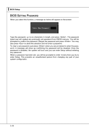
... the password, up confirming the password will replace any previously set , you are prompted to enter the password. This prevents an unauthorized person from CMOS memory. You may also press to abort the selection and not enter a password. A message will show up to six characters in length, and press . You will...
... the password, up confirming the password will replace any previously set , you are prompted to enter the password. This prevents an unauthorized person from CMOS memory. You may also press to abort the selection and not enter a password. A message will show up to six characters in length, and press . You will...
User Guide
Page 59
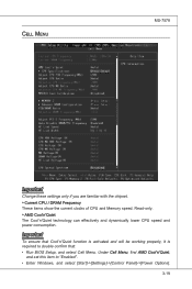
... Change these settings only if you are familiar with the chipset. ▶ Current CPU / DRAM Frequency These items show the current clocks of CPU and Memory speed. Read-only. ▶ AMD Cool'n'Quiet The Cool'n'Quiet technology can effectively and dynamically lower CPU speed and power consumption. Important To ensure that...
... Change these settings only if you are familiar with the chipset. ▶ Current CPU / DRAM Frequency These items show the current clocks of CPU and Memory speed. Read-only. ▶ AMD Cool'n'Quiet The Cool'n'Quiet technology can effectively and dynamically lower CPU speed and power consumption. Important To ensure that...
User Guide
Page 61
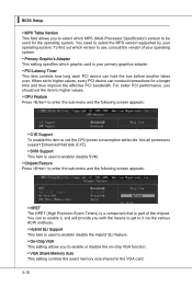
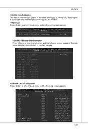
Setting to [Enabled] allows you to enter the sub-menu and the following screen appears. 3-21 This submenu displays the information of installed memory. ▶ Advance DRAM Configuration Press to enter the sub-menu and the following screen appears. It is for overclock. MS-7578 ▶ NVIDIA Core Calibration This item is available only when the processor supports this function. ▶ Memory-Z Press to enter the sub-menu and the following screen appears. ▶ DIMM1~4 Memory SPD Information Press to set the CPU Ratio higher.
Setting to [Enabled] allows you to enter the sub-menu and the following screen appears. 3-21 This submenu displays the information of installed memory. ▶ Advance DRAM Configuration Press to enter the sub-menu and the following screen appears. It is for overclock. MS-7578 ▶ NVIDIA Core Calibration This item is available only when the processor supports this function. ▶ Memory-Z Press to enter the sub-menu and the following screen appears. ▶ DIMM1~4 Memory SPD Information Press to set the CPU Ratio higher.
User Guide
Page 62
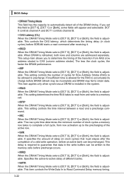
... clock cycles) before SDRAM starts a read command after the completion of a valid write operation, before an active bank can be written to the memory cells before DRAM refresh may be incomplete and DRAM may fail to retain data. This setting controls the number of different banks. ▶ tWTR ...If insufficient time is allowed for Row Address Strobe (RAS) to be precharged. This setting controls the time interval between a read from and write to a memory cell. ▶ tRTP When the DRAM Timing Mode sets to [DCT 0], [DCT1] or [Both], the field is adjustable. This delay is required to ...
... clock cycles) before SDRAM starts a read command after the completion of a valid write operation, before an active bank can be written to the memory cells before DRAM refresh may be incomplete and DRAM may fail to retain data. This setting controls the number of different banks. ▶ tWTR ...If insufficient time is allowed for Row Address Strobe (RAS) to be precharged. This setting controls the time interval between a read from and write to a memory cell. ▶ tRTP When the DRAM Timing Mode sets to [DCT 0], [DCT1] or [Both], the field is adjustable. This delay is required to ...
User Guide
Page 63
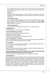
... up. 3-23 Remember to disable Spread Spectrum if you to select the ratio of FSB/ DRAM. ▶ Adjusted DRAM Frequency (MHz) It shows the adjusted Memory frequency. These settings determine the time RFC take to read command to the same internal bank of the DDR device. ▶ tRFC0~3 When the DRAM...fields are adjustable. This field controls the SDRAM command rate. Setting to [Auto], the system will remove (turn off) clocks from and write to memory cells. ▶ 1T/2T Memory Timing When the DRAM Timing Mode sets to [DCT 0], [DCT1] or [Both], the field is used to adjust the voltage of CPU...
... up. 3-23 Remember to disable Spread Spectrum if you to select the ratio of FSB/ DRAM. ▶ Adjusted DRAM Frequency (MHz) It shows the adjusted Memory frequency. These settings determine the time RFC take to read command to the same internal bank of the DDR device. ▶ tRFC0~3 When the DRAM...fields are adjustable. This field controls the SDRAM command rate. Setting to [Auto], the system will remove (turn off) clocks from and write to memory cells. ▶ 1T/2T Memory Timing When the DRAM Timing Mode sets to [DCT 0], [DCT1] or [Both], the field is used to adjust the voltage of CPU...
User Guide
Page 109
Before you install the Overclocking Center, please make sure the system has meet the following requirements: 1. 256MB system memory. 2. DVD-ROM drive for software installation. 3. DotNet Frame Work 2.0 B-C-1 Operation system: Windows XP or up. 4. Appendix C Overclocking Center Overclocking Center, the most useful and powerful utility that MSI has spent much research and efforts to develop, helps users to monitor or configure the hardware status of MSI Mainboard in windows, such as CPU clock, voltage, fan speed and temperature.
Before you install the Overclocking Center, please make sure the system has meet the following requirements: 1. 256MB system memory. 2. DVD-ROM drive for software installation. 3. DotNet Frame Work 2.0 B-C-1 Operation system: Windows XP or up. 4. Appendix C Overclocking Center Overclocking Center, the most useful and powerful utility that MSI has spent much research and efforts to develop, helps users to monitor or configure the hardware status of MSI Mainboard in windows, such as CPU clock, voltage, fan speed and temperature.


