User Guide
Page 2
... help resources for further guidance. ◙ Visit the MSI website for NF750-G55 Date July 2009 Technical Support If a problem arises with your place of MICRO-STAR INTERNATIONAL. Revision History Revision V1.0 Revision History First release for FAQ, technical guide, BIOS updates, driver updates, and other information: http://www.msi.com/index.php?func=service ◙ Contact our technical staff at: http://ocss...
... help resources for further guidance. ◙ Visit the MSI website for NF750-G55 Date July 2009 Technical Support If a problem arises with your place of MICRO-STAR INTERNATIONAL. Revision History Revision V1.0 Revision History First release for FAQ, technical guide, BIOS updates, driver updates, and other information: http://www.msi.com/index.php?func=service ◙ Contact our technical staff at: http://ocss...
User Guide
Page 8
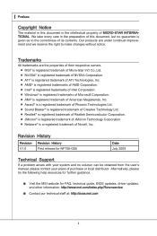
... Started 1-1 Mainboard Specifications 1-2 Mainboard Layout 1-4 Packing Checklist 1-5 Chapter 2 Hardware Setup 2-1 Quick Components Guide 2-2 CPU (Central Processing Unit 2-3 Memory 2-6 Power Supply 2-8 Back Panel 2-9 Connectors 2-11 Switch 2-17 Jumpers 2-18 Button 2-19 Slots 2-20 LED Status Indicators 2-24 Chapter 3 BIOS Setup 3-1 Entering Setup 3-2 The Main Menu 3-4 Standard CMOS Features 3-6 Advanced BIOS Features 3-9 Integrated Peripherals 3-12 Power Management Setup 3-14 H/W Monitor 3-16 Green Power 3-17 BIOS Setting Password 3-18 Cell Menu 3-19 User Settings...
... Started 1-1 Mainboard Specifications 1-2 Mainboard Layout 1-4 Packing Checklist 1-5 Chapter 2 Hardware Setup 2-1 Quick Components Guide 2-2 CPU (Central Processing Unit 2-3 Memory 2-6 Power Supply 2-8 Back Panel 2-9 Connectors 2-11 Switch 2-17 Jumpers 2-18 Button 2-19 Slots 2-20 LED Status Indicators 2-24 Chapter 3 BIOS Setup 3-1 Entering Setup 3-2 The Main Menu 3-4 Standard CMOS Features 3-6 Advanced BIOS Features 3-9 Integrated Peripherals 3-12 Power Management Setup 3-14 H/W Monitor 3-16 Green Power 3-17 BIOS Setting Password 3-18 Cell Menu 3-19 User Settings...
User Guide
Page 22
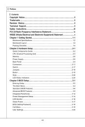
... compatible. Installed Empty 1 DIMM1 DIMM2 DIMM3 DIMM4 2 DIMM1 DIMM2 DIMM3 DIMM4 Important • DDR3 memory modules are used for Dual-Channel mode. For more information on compatible components, please visit http://www.msi.com/index.php?func=testreport DDR3 240-pin, 1.5V 48x2=96 pin 72x2=144 pin Dual-Channel mode Population Rule In Dual-Channel mode, the memory modules can enhance the system performance. ▍ Hardware Setup Memory These DIMM slots...
... compatible. Installed Empty 1 DIMM1 DIMM2 DIMM3 DIMM4 2 DIMM1 DIMM2 DIMM3 DIMM4 Important • DDR3 memory modules are used for Dual-Channel mode. For more information on compatible components, please visit http://www.msi.com/index.php?func=testreport DDR3 240-pin, 1.5V 48x2=96 pin 72x2=144 pin Dual-Channel mode Population Rule In Dual-Channel mode, the memory modules can enhance the system performance. ▍ Hardware Setup Memory These DIMM slots...
User Guide
Page 24
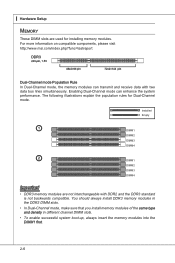
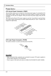
... power supply firmly into the connector. ▍ Hardware Setup Power Supply ATX 24-pin Power Connector: JPWR1 This connector allows you to ensure stable operation of the mainboard. • Power supply of the power supply is inserted in the proper orientation and the pins are connected to proper ATX power supplies to connect an ATX 24-pin power supply. If you like to use the 20-pin ATX power supply as you 'd like . You may use the 20-pin ATX power supply, please plug your power supply along with pin 1 & pin...
... power supply firmly into the connector. ▍ Hardware Setup Power Supply ATX 24-pin Power Connector: JPWR1 This connector allows you to ensure stable operation of the mainboard. • Power supply of the power supply is inserted in the proper orientation and the pins are connected to proper ATX power supplies to connect an ATX 24-pin power supply. If you like to use the 20-pin ATX power supply as you 'd like . You may use the 20-pin ATX power supply, please plug your power supply along with pin 1 & pin...
User Guide
Page 25
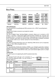
... Interface-Digital) connector allows you to your monitor manual for more information.) ▶ USB Ports The USB (Universal Serial Bus) port is for attaching USB devices such as keyboard, mouse, or other USB-compatible devices. ▶ HDMI Port The High-Definition Multimedia Interface (HDMI) is an all-digital audio/video interface capable of transmitting uncompressed streams. HDMI supports all TV format, including standard, enhanced, or high-definition video, plus multi-channel digital audio on the LAN. 10 Mbits...
... Interface-Digital) connector allows you to your monitor manual for more information.) ▶ USB Ports The USB (Universal Serial Bus) port is for attaching USB devices such as keyboard, mouse, or other USB-compatible devices. ▶ HDMI Port The High-Definition Multimedia Interface (HDMI) is an all-digital audio/video interface capable of transmitting uncompressed streams. HDMI supports all TV format, including standard, enhanced, or high-definition video, plus multi-channel digital audio on the LAN. 10 Mbits...
User Guide
Page 27
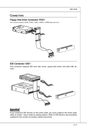
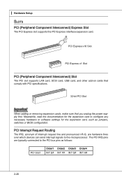
...or 3 1/2" F l oppy D i sk D r i ve Connector 3 1/2" F l oppy D i sk D ri ve Connector MS-7578 IDE Connector: IDE1 This connector supports IDE hard disk drives, optical disk drives and other IDE devices. Refer to master / slave mode by the vendors for jumper setting instructions. 2-11 Connectors Floppy Disk Drive Connector: FDD1 This connector supports 360KB, 720KB, 1.2MB, 1.44MB or 2.88MB floppy disk drive. Fl opMpySDI FlopMpySDIFlopMpySDI Kdkldkddfkkakfskkdskkdakaddfdddffdfkad-dkdffdlkdddjdafddsddjfdddfkadfasdfdddffdfadasfsadfddsddadasdasddsdafsddadsdddfdsadddfffaffsfsdasfdfffdf...
...or 3 1/2" F l oppy D i sk D r i ve Connector 3 1/2" F l oppy D i sk D ri ve Connector MS-7578 IDE Connector: IDE1 This connector supports IDE hard disk drives, optical disk drives and other IDE devices. Refer to master / slave mode by the vendors for jumper setting instructions. 2-11 Connectors Floppy Disk Drive Connector: FDD1 This connector supports 360KB, 720KB, 1.2MB, 1.44MB or 2.88MB floppy disk drive. Fl opMpySDI FlopMpySDIFlopMpySDI Kdkldkddfkkakfskkdskkdakaddfdddffdfkad-dkdffdlkdddjdafddsddjfdddfkadfasdfdddffdfadasfsadfddsddadasdasddsdafsddadsdddfdsadddfffaffsfsdasfdfffdf...
User Guide
Page 29
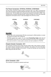
... mainboard has a System Hardware Monitor chipset on the screen. You can install Overclocking Center utility that the red wire is opened, the chassis intrusion mechanism will be connected to take advantage of the CPU fan control. The system will automatically control the CPU fan speed according to the actual CPU temperature. • Fan cooler set with speed sensor to GND. MS-7578 Fan Power Connectors: CPUFAN, SYSFAN1, SYSFAN2/3 The fan power connectors support system cooling fan with +12V. When connecting the wire...
... mainboard has a System Hardware Monitor chipset on the screen. You can install Overclocking Center utility that the red wire is opened, the chassis intrusion mechanism will be connected to take advantage of the CPU fan control. The system will automatically control the CPU fan speed according to the actual CPU temperature. • Fan cooler set with speed sensor to GND. MS-7578 Fan Power Connectors: CPUFAN, SYSFAN1, SYSFAN2/3 The fan power connectors support system cooling fan with +12V. When connecting the wire...

User Guide
Page 34
▍ Hardware Setup Jumpers Clear CMOS Jumper: JBAT1 There is on . Avoid clearing the CMOS while the system is a CMOS RAM onboard that has a power supply from an external battery to keep the data of system configuration. If you want to clear the system configuration, set the jumper to 1-2 pin position. With the CMOS RAM, the system can clear CMOS by shorting 2-3 pin while the system is turned on ; it is off. Then return to clear data. 1 JBAT1 1 Keep Data 1 Clear Data Important You can automatically boot OS every time it will damage the mainboard. 2-18
▍ Hardware Setup Jumpers Clear CMOS Jumper: JBAT1 There is on . Avoid clearing the CMOS while the system is a CMOS RAM onboard that has a power supply from an external battery to keep the data of system configuration. If you want to clear the system configuration, set the jumper to 1-2 pin position. With the CMOS RAM, the system can clear CMOS by shorting 2-3 pin while the system is turned on ; it is off. Then return to clear data. 1 JBAT1 1 Keep Data 1 Clear Data Important You can automatically boot OS every time it will damage the mainboard. 2-18
User Guide
Page 36
The PCI IRQ pins are hardware lines over which devices can send interrupt signals to the microprocessor. ▍ Hardware Setup Slots PCI (Peripheral Component Interconnect) Express Slot The PCI Express slot supports the PCI Express interface expansion card. PCI Express x16 Slot PCI Express x1 Slot PCI (Peripheral Component Interconnect) Slot The PCI slot supports LAN card, SCSI card, USB card, and other add-on cards that comply with PCI specifications. 32-bit PCI Slot Important When adding or removing expansion cards, make sure that you unplug the power supply first. PCI ...
The PCI IRQ pins are hardware lines over which devices can send interrupt signals to the microprocessor. ▍ Hardware Setup Slots PCI (Peripheral Component Interconnect) Express Slot The PCI Express slot supports the PCI Express interface expansion card. PCI Express x16 Slot PCI Express x1 Slot PCI (Peripheral Component Interconnect) Slot The PCI slot supports LAN card, SCSI card, USB card, and other add-on cards that comply with PCI specifications. 32-bit PCI Slot Important When adding or removing expansion cards, make sure that you unplug the power supply first. PCI ...
User Guide
Page 37
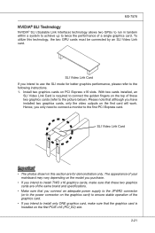
... to use the SLI mode for demonstration only. MS-7578 NVIDIA® SLI Technology NVIDIA® SLI (Scalable Link Interface) technology allows two GPUs to run in this technology, the two GPU cards must be connected by an SLI Video Link card. Please note that the graphics card is required to connect the golden fingers on the first PCIE x16 (PCI_E2) slot. 2-21 Install two graphics cards on the first card will work.
... to use the SLI mode for demonstration only. MS-7578 NVIDIA® SLI Technology NVIDIA® SLI (Scalable Link Interface) technology allows two GPUs to run in this technology, the two GPU cards must be connected by an SLI Video Link card. Please note that the graphics card is required to connect the golden fingers on the first PCIE x16 (PCI_E2) slot. 2-21 Install two graphics cards on the first card will work.
User Guide
Page 39
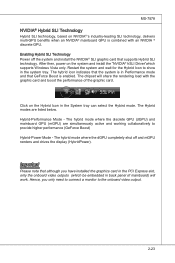
... have installed the graphics card in the PCI Express slot, only the onboard video outputs (which supports Windows Vista only. Important Please note that although you only need to connect a monitor to provide higher performance (GeForce Boost) Hybrid-Power Mode - MS-7578 NVIDIA® Hybrid SLI Technology Hybrid SLI technology, based on NVIDIA®'s industry-leading SLI technology, delivers multi-GPU benefits when an NVIDIA® mainboard GPU is enabled. The chipset will work...
... have installed the graphics card in the PCI Express slot, only the onboard video outputs (which supports Windows Vista only. Important Please note that although you only need to connect a monitor to provide higher performance (GeForce Boost) Hybrid-Power Mode - MS-7578 NVIDIA® Hybrid SLI Technology Hybrid SLI technology, based on NVIDIA®'s industry-leading SLI technology, delivers multi-GPU benefits when an NVIDIA® mainboard GPU is enabled. The chipset will work...
User Guide
Page 47
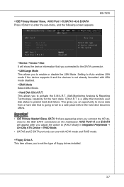
... Auto enables LBA mode if the device supports it and the devices is a utility that monitors your disk status to predict hard disk failure. S.M.A.R.T is not already formatted with ACHI mode and RAID mode. ▶ Floppy Drive A This item allows you to enable or disable the LBA Mode. This gives you an opportunity to move data from a hard disk that you connected to the SATA connector. ▶ LBA/Large Mode This allows you to set the type of floppy drives installed...
... Auto enables LBA mode if the device supports it and the devices is a utility that monitors your disk status to predict hard disk failure. S.M.A.R.T is not already formatted with ACHI mode and RAID mode. ▶ Floppy Drive A This item allows you to enable or disable the LBA Mode. This gives you an opportunity to move data from a hard disk that you connected to the SATA connector. ▶ LBA/Large Mode This allows you to set the type of floppy drives installed...
User Guide
Page 49
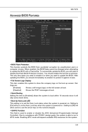
... to disable it is powered on the boot-up screen. Enabling APIC mode will skip some check items. ▶ Boot Up Num-Lock LED This setting is to enable or disable the APIC (Advanced Programmable Interrupt Controller). Advanced BIOS Features MS-7578 ▶ BIOS Flash Protection This function protects the BIOS from accidental corruption by unauthorized users or computer viruses. Setting to [On] will turn on the Num Lock key...
... to disable it is powered on the boot-up screen. Enabling APIC mode will skip some check items. ▶ Boot Up Num-Lock LED This setting is to enable or disable the APIC (Advanced Programmable Interrupt Controller). Advanced BIOS Features MS-7578 ▶ BIOS Flash Protection This function protects the BIOS from accidental corruption by unauthorized users or computer viruses. Setting to [On] will turn on the Num Lock key...
User Guide
Page 50
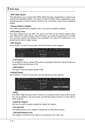
...; Hybrid SLI Support This item is part of your operating system. ▶ Primary Graphic's Adapter This setting specifies which MPS (Multi-Processor Specification) version to be used to enable/ disable the Hybrid SLI feature. ▶ On-Chip VGA This setting allows you to enable or disable the on-chip VGA function. ▶ VGA Share Memory Auto This setting controls the exact memory size shared to the VGA card. 3-10 For better PCI performance, you should set to red the CPU power consumption...
...; Hybrid SLI Support This item is part of your operating system. ▶ Primary Graphic's Adapter This setting specifies which MPS (Multi-Processor Specification) version to be used to enable/ disable the Hybrid SLI feature. ▶ On-Chip VGA This setting allows you to enable or disable the on-chip VGA function. ▶ VGA Share Memory Auto This setting controls the exact memory size shared to the VGA card. 3-10 For better PCI performance, you should set to red the CPU power consumption...
User Guide
Page 52
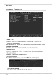
...; BIOS Setup Integrated Peripherals ▶ USB Controller This setting allows you to enable/disable the onboard USB 1.1/ 2.0 controller. ▶ USB Device Legacy Support Select [Enabled] if you need to use a USB-interfaced device in the operating system. ▶ Onboard LAN Controller This setting allows you to enable/disable the onboard LAN controller. ▶ LAN Option ROM This item is used to decide whether to invoke the Boot ROM of the onboard LAN. ▶ HD Audio Controller This setting is used to select the audio codec. ▶ On-Chip ATA Devices Press to enter...
...; BIOS Setup Integrated Peripherals ▶ USB Controller This setting allows you to enable/disable the onboard USB 1.1/ 2.0 controller. ▶ USB Device Legacy Support Select [Enabled] if you need to use a USB-interfaced device in the operating system. ▶ Onboard LAN Controller This setting allows you to enable/disable the onboard LAN controller. ▶ LAN Option ROM This item is used to decide whether to invoke the Boot ROM of the onboard LAN. ▶ HD Audio Controller This setting is used to select the audio codec. ▶ On-Chip ATA Devices Press to enter...
User Guide
Page 54
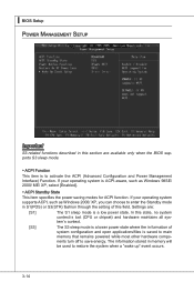
... formation of this section are : [S1] The S1 sleep mode is saved to main memory that remains powered while most other hardware compo- Settings are available only when the BIOS supports S3 sleep mode. ▶ ACPI Function This item is ACPI-aware, such as Windows 2000/ XP, you can choose to activate the ACPI (Advanced Configuration and Power Management Interface) Function. The information stored in S1...
... formation of this section are : [S1] The S1 sleep mode is saved to main memory that remains powered while most other hardware compo- Settings are available only when the BIOS supports S3 sleep mode. ▶ ACPI Function This item is ACPI-aware, such as Windows 2000/ XP, you can choose to activate the ACPI (Advanced Configuration and Power Management Interface) Function. The information stored in S1...
User Guide
Page 55
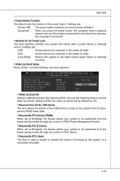
... Setup Press and the following sub-menu appears. ▶ Wake Up Event By Setting to [BIOS] activates the following fields, and use the following fields to set to [Enabled], the feature allows your system to be awakened from the power saving modes through any event on PCIE device. ▶ Resume By RTC Alarm The field is used to enable or disable the feature of the power button...
... Setup Press and the following sub-menu appears. ▶ Wake Up Event By Setting to [BIOS] activates the following fields, and use the following fields to set to [Enabled], the feature allows your system to be awakened from the power saving modes through any event on PCIE device. ▶ Resume By RTC Alarm The field is used to enable or disable the feature of the power button...
User Guide
Page 56
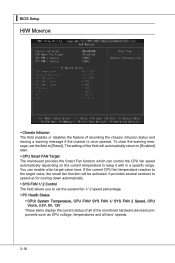
... FAN 2 Speed, CPU Vcore, 3.3V, 5V, 12V These items display the current status of all of the monitored hardware devices/components such as CPU voltage, temperatures and all fans' speeds. 3-16 The setting of recording the chassis intrusion status and issuing a warning message if the chassis is once opened. You can control the CPU fan speed automatically depending on the current temperature to [Reset]. ▍ BIOS Setup H/W Monitor ▶ Chassis Intrusion The field enables or disables...
... FAN 2 Speed, CPU Vcore, 3.3V, 5V, 12V These items display the current status of all of the monitored hardware devices/components such as CPU voltage, temperatures and all fans' speeds. 3-16 The setting of recording the chassis intrusion status and issuing a warning message if the chassis is once opened. You can control the CPU fan speed automatically depending on the current temperature to [Reset]. ▍ BIOS Setup H/W Monitor ▶ Chassis Intrusion The field enables or disables...
User Guide
Page 93
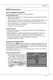
.... Boot from the Windows CD, use the floppy disk that are to copy and install the nForce RAID software. (Check p.B-7 for details.) 2. Initialize the NVRAID Array Disks. NVRAID BIOS setup lets you choose the RAID array type and which hard drives you to loading the OS. 2. Entering the RAID BIOS Setup 1. After rebooting your PC, wait until you see the RAID software prompting you want to set to enable the RAID function in BIOS before configuring the...
.... Boot from the Windows CD, use the floppy disk that are to copy and install the nForce RAID software. (Check p.B-7 for details.) 2. Initialize the NVRAID Array Disks. NVRAID BIOS setup lets you choose the RAID array type and which hard drives you to loading the OS. 2. Entering the RAID BIOS Setup 1. After rebooting your PC, wait until you see the RAID software prompting you want to set to enable the RAID function in BIOS before configuring the...
User Guide
Page 97
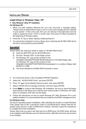
... Windows once for NVIDIA RAID Controller is recommended that hard drive. a] Insert the MSI DVD into the A: drive,and then press ENTER. Be sure to supply the driver. And then, follow the instruction below to insert a floppy disk containing the NVIDIA RAID driver into the DVD-ROM drive. Follow the instructions on the Setup screen. If this is not the case, then press F6 when prompted at the Specify Devices screen, then press ENTER. 7. When you start installing Windows...
... Windows once for NVIDIA RAID Controller is recommended that hard drive. a] Insert the MSI DVD into the A: drive,and then press ENTER. Be sure to supply the driver. And then, follow the instruction below to insert a floppy disk containing the NVIDIA RAID driver into the DVD-ROM drive. Follow the instructions on the Setup screen. If this is not the case, then press F6 when prompted at the Specify Devices screen, then press ENTER. 7. When you start installing Windows...


