User Guide
Page 3
... has been exposed to moisture. ◯ The equipment does not work well or you can not step on the enclosure are for recycleing special disposal. MS-7578 Safety Instructions ■ Always read the safety instructions carefully. ■ Keep this User's Manual for future reference. ■ Keep this equipment on a reliable flat surface...
... has been exposed to moisture. ◯ The equipment does not work well or you can not step on the enclosure are for recycleing special disposal. MS-7578 Safety Instructions ■ Always read the safety instructions carefully. ■ Keep this User's Manual for future reference. ■ Keep this equipment on a reliable flat surface...
User Guide
Page 4
... , the user is no guarantee that to which can radiate radio frequency energy and, if not installed and used in a particular installation. Micro-Star International MS-7578 This device complies with Part 15 of the FCC Rules.
... , the user is no guarantee that to which can radiate radio frequency energy and, if not installed and used in a particular installation. Micro-Star International MS-7578 This device complies with Part 15 of the FCC Rules.
User Guide
Page 5
...certains produits en fin de vie. und Elektronik-Altgeräte nicht mehr als kommunale Abfälle entsorgt werden. MSI hat europaweit verschiedene Sammel- Bitte entsorgen Sie dieses Produkt zum gegebenen Zeitpunkt ausschliesslich an einer lokalen Altgerätesammelstelle in Verkehr... takes effect on August 13, 2005, products of "electrical and electronic equipment" cannot be obligated to local collection points. MS-7578 WEEE (Waste Electrical and Electronic Equipment) Statement ENGLISH To protect the global environment and as municipal waste anymore and manufacturers of...
...certains produits en fin de vie. und Elektronik-Altgeräte nicht mehr als kommunale Abfälle entsorgt werden. MSI hat europaweit verschiedene Sammel- Bitte entsorgen Sie dieses Produkt zum gegebenen Zeitpunkt ausschliesslich an einer lokalen Altgerätesammelstelle in Verkehr... takes effect on August 13, 2005, products of "electrical and electronic equipment" cannot be obligated to local collection points. MS-7578 WEEE (Waste Electrical and Electronic Equipment) Statement ENGLISH To protect the global environment and as municipal waste anymore and manufacturers of...
User Guide
Page 9
MS-7578 Load Fail-Safe/ Optimized Defaults 3-27 Appendix A Realtek Audio A-1 Installing the Realtek HD Audio Driver A-2 Software Configuration A-4 Hardware Setup A-19 Appendix B NVIDIA RAID B-1 Introduction B-2 RAID Configuration B-3 Installing Driver B-7 NVIDIA RAID Utility Installation B-8 Using the NVMediaShield Software B-11 Appendix C Overclocking Center C-1 Activating Overclocking Center C-2 System Info C-3 DOT C-5 ix
MS-7578 Load Fail-Safe/ Optimized Defaults 3-27 Appendix A Realtek Audio A-1 Installing the Realtek HD Audio Driver A-2 Software Configuration A-4 Hardware Setup A-19 Appendix B NVIDIA RAID B-1 Introduction B-2 RAID Configuration B-3 Installing Driver B-7 NVIDIA RAID Utility Installation B-8 Using the NVMediaShield Software B-11 Appendix C Overclocking Center C-1 Activating Overclocking Center C-2 System Info C-3 DOT C-5 ix
User Guide
Page 11
Chapter 1 Getting Started Thank you for optimal system efficiency. Designed to fit the advanced AMD® processor in AM3 package processor, the NF750-G55 Series deliver a high performance and professional desktop platform solution. 1-1-1 The NF750-G55 Series mainboards are based on NVIDIA® nForce 750a SLI single chipset for choosing the NF750-G55 Series (MS-7578 v1.X) ATX mainboard.
Chapter 1 Getting Started Thank you for optimal system efficiency. Designed to fit the advanced AMD® processor in AM3 package processor, the NF750-G55 Series deliver a high performance and professional desktop platform solution. 1-1-1 The NF750-G55 Series mainboards are based on NVIDIA® nForce 750a SLI single chipset for choosing the NF750-G55 Series (MS-7578 v1.X) ATX mainboard.
User Guide
Page 13
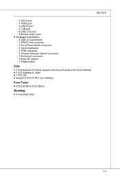
MS-7578 - 1 DVI-D port - 1 HDMI port - 1 eSATA port - 1 LAN jack - 6 USB 2.0 ports - 6 flexible audio jacks ■ On-Board Connectors - 3 USB 2.0 connectors - 1 SPDIF-Out connector - 1 Front Panel Audio ... (support into two x 8 ports when SLI Enabled) ■ 2 PCI Express x1 slots ■ 1 PCI slot ■ Support 3.3V/ 5V PCI bus Interface Form Factor ■ ATX (30.48cm X 22.38cm) Mounting ■ 6 mounting holes 1-3
MS-7578 - 1 DVI-D port - 1 HDMI port - 1 eSATA port - 1 LAN jack - 6 USB 2.0 ports - 6 flexible audio jacks ■ On-Board Connectors - 3 USB 2.0 connectors - 1 SPDIF-Out connector - 1 Front Panel Audio ... (support into two x 8 ports when SLI Enabled) ■ 2 PCI Express x1 slots ■ 1 PCI slot ■ Support 3.3V/ 5V PCI bus Interface Form Factor ■ ATX (30.48cm X 22.38cm) Mounting ■ 6 mounting holes 1-3
User Guide
Page 14
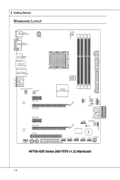
▍ Getting Started Mainboard Layout Top : mouse Bottom:keyboard Top: VGA port Bottom:DVI port JPWR2 CPUFAN JPWR1 Top: USB ports Bottom:HDMI T:USB ports B:eSATA port Top:LAN Jack Bottom: USB ports T:Line-In M:Line-Out B:Mic T:RS-Out M:CS-Out B:SS-Out EZ_OC_SWITCH1 ON SYSFAN1 12 PCI_E1 PCI_E2 NVIDIA nForce 750a SLI SOCKET AM3 DIMM1 DIMM2 DIMM3 DIMM4 JSPI1 SYSFAN2 JBAT1 IDE 1 SATA1_2 SATA3_4 PCI_E3 PCI_E4 PCI1 JAUD1 JCD1 JSP1 JTPM1 SYSFAN3 JCI1 JCOM1 JUSB1 JUSB2 JUSB3 JFP1 POWER1 FDD 1 NF750-G55 Series (MS-7578 v1.X) Mainboard SATA5 BATT + JFP2 1-4
▍ Getting Started Mainboard Layout Top : mouse Bottom:keyboard Top: VGA port Bottom:DVI port JPWR2 CPUFAN JPWR1 Top: USB ports Bottom:HDMI T:USB ports B:eSATA port Top:LAN Jack Bottom: USB ports T:Line-In M:Line-Out B:Mic T:RS-Out M:CS-Out B:SS-Out EZ_OC_SWITCH1 ON SYSFAN1 12 PCI_E1 PCI_E2 NVIDIA nForce 750a SLI SOCKET AM3 DIMM1 DIMM2 DIMM3 DIMM4 JSPI1 SYSFAN2 JBAT1 IDE 1 SATA1_2 SATA3_4 PCI_E3 PCI_E4 PCI1 JAUD1 JCD1 JSP1 JTPM1 SYSFAN3 JCI1 JCOM1 JUSB1 JUSB2 JUSB3 JFP1 POWER1 FDD 1 NF750-G55 Series (MS-7578 v1.X) Mainboard SATA5 BATT + JFP2 1-4
User Guide
Page 15
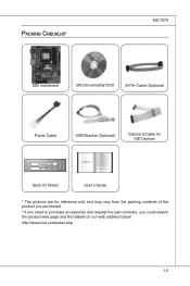
Packing Checklist MS-7578 MSI mainboard MSI Driver/Utility DVD SATA Cable (Optional) Power Cable USB Bracket (Optional) Standard Cable for IDE Devices Back IO Shield User's Guide * The pictures are for reference only and may vary from the packing contents of the product you purchased. * If you need to purchase accessories and request the part numbers, you could search the product web page and find details on our web address below http://www.msi.com/index.php 1-5
Packing Checklist MS-7578 MSI mainboard MSI Driver/Utility DVD SATA Cable (Optional) Power Cable USB Bracket (Optional) Standard Cable for IDE Devices Back IO Shield User's Guide * The pictures are for reference only and may vary from the packing contents of the product you purchased. * If you need to purchase accessories and request the part numbers, you could search the product web page and find details on our web address below http://www.msi.com/index.php 1-5
User Guide
Page 19
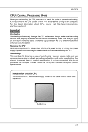
... dissipation. Replacing the CPU While replacing the CPU, always turn off the ATX power supply or unplug the power supply's power cord from overheating. Gold arrow 2-3 Remember to AM3 CPU The surface of CPU. MS-7578 CPU (Central Processing Unit) When you are able to tolerate such abnormal ...setting, while doing overclocking. For the latest information about CPU, please visit http://www.msi.com/index. Always make sure the cooling fan can work ...
... dissipation. Replacing the CPU While replacing the CPU, always turn off the ATX power supply or unplug the power supply's power cord from overheating. Gold arrow 2-3 Remember to AM3 CPU The surface of CPU. MS-7578 CPU (Central Processing Unit) When you are able to tolerate such abnormal ...setting, while doing overclocking. For the latest information about CPU, please visit http://www.msi.com/index. Always make sure the cooling fan can work ...
User Guide
Page 21
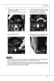
... model you purchase. • While disconnecting the Safety Hook from the fixed bolt, the fixed lever will spring back instantly. 2-5 Then press down the lever. 8. MS-7578 5.
... model you purchase. • While disconnecting the Safety Hook from the fixed bolt, the fixed lever will spring back instantly. 2-5 Then press down the lever. 8. MS-7578 5.
User Guide
Page 23
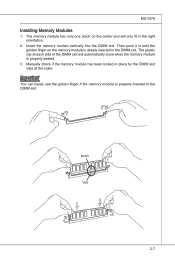
... module has been locked in place by the DIMM slot clips at each side of the DIMM slot will only fit in the right orientation. 2. MS-7578 Installing Memory Modules 1. The memory module has only one notch on the memory module is deeply inserted in the DIMM slot. Insert the memory module...
... module has been locked in place by the DIMM slot clips at each side of the DIMM slot will only fit in the right orientation. 2. MS-7578 Installing Memory Modules 1. The memory module has only one notch on the memory module is deeply inserted in the DIMM slot. Insert the memory module...
User Guide
Page 25
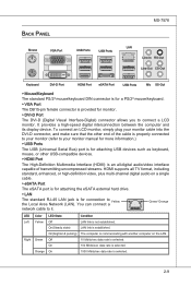
... the eSATA external hard drive. ▶ LAN The standard RJ-45 LAN jack is not established. Back Panel Mouse VGA Port USB Ports USB Ports MS-7578 LAN Line-In RS-Out Line-Out CS-Out Keyboard DVI-D Port HDMI Port eSATA Port USB Ports Mic SS-Out ▶ Mouse/Keyboard The...
... the eSATA external hard drive. ▶ LAN The standard RJ-45 LAN jack is not established. Back Panel Mouse VGA Port USB Ports USB Ports MS-7578 LAN Line-In RS-Out Line-Out CS-Out Keyboard DVI-D Port HDMI Port eSATA Port USB Ports Mic SS-Out ▶ Mouse/Keyboard The...
User Guide
Page 27
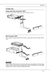
... vendors for jumper setting instructions. 2-11 Fl opMpySDI Kdkldkddfkkakfskkdskkdakaddfdddffdfkad-dkdffdldkddjadfdsdddjfdddffkadasdfdddffdfadasfsadfddsddadasdsaddsdafsddadsdddfdsadddfffaffsfsdasfdfffdf 5 D 1i s/k4"DFr il voeppCyonnect or 3 1/2" F l oppy D i sk D r i ve Connector 3 1/2" F l oppy D i sk D ri ve Connector MS-7578 IDE Connector: IDE1 This connector supports IDE hard disk drives, optical disk drives and other IDE devices. Connectors Floppy Disk Drive Connector: FDD1 This connector...
... vendors for jumper setting instructions. 2-11 Fl opMpySDI Kdkldkddfkkakfskkdskkdakaddfdddffdfkad-dkdffdldkddjadfdsdddjfdddffkadasdfdddffdfadasfsadfddsddadasdsaddsdafsddadsdddfdsadddfffaffsfsdasfdfffdf 5 D 1i s/k4"DFr il voeppCyonnect or 3 1/2" F l oppy D i sk D r i ve Connector 3 1/2" F l oppy D i sk D ri ve Connector MS-7578 IDE Connector: IDE1 This connector supports IDE hard disk drives, optical disk drives and other IDE devices. Connectors Floppy Disk Drive Connector: FDD1 This connector...
User Guide
Page 29
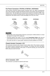
... black wire is provided for proper CPU cooling fan. • CPUFAN supports fan control. If the mainboard has a System Hardware Monitor chipset on the screen. MS-7578 Fan Power Connectors: CPUFAN, SYSFAN1, SYSFAN2/3 The fan power connectors support system cooling fan with 3 or 4 pins power connector are both available for CPUFAN Chassis...
... black wire is provided for proper CPU cooling fan. • CPUFAN supports fan control. If the mainboard has a System Hardware Monitor chipset on the screen. MS-7578 Fan Power Connectors: CPUFAN, SYSFAN1, SYSFAN2/3 The fan power connectors support system cooling fan with 3 or 4 pins power connector are both available for CPUFAN Chassis...
User Guide
Page 31
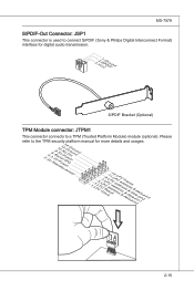
... connect S/PDIF (Sony & Philips Digital Interconnect Format) interface for more details and usages. 1.L3P.L5CP.LCC7P.loLRC9cP.eLka1CsPd1e1ad.CtL3drPea.dLsdCrPsedasCr&edsFdsd&sraraedt&amsasdpteaa&intpa0dinap1tian2pin3 2-15 MS-7578 S/PDIF-Out Connector: JSP1 This connector is used to a TPM (Trusted Platform Module) module (optional).
... connect S/PDIF (Sony & Philips Digital Interconnect Format) interface for more details and usages. 1.L3P.L5CP.LCC7P.loLRC9cP.eLka1CsPd1e1ad.CtL3drPea.dLsdCrPsedasCr&edsFdsd&sraraedt&amsasdpteaa&intpa0dinap1tian2pin3 2-15 MS-7578 S/PDIF-Out Connector: JSP1 This connector is used to a TPM (Trusted Platform Module) module (optional).
User Guide
Page 33
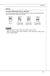
MS-7578 Switch Overclock FSB Switch: EZ_OC_SWITCH1 You can overclock the FSB to default setting. 2-17 Default Increase 10% speed of FSB Increase 15% speed of FSB Increase 20% speed of FSB Important • Make sure that you power off the system before setting the switch. • When overclocking cause system instability or crash during boot, please set the FSB. Follow the instructions below to set the switch to increase the processor frequency by changing the switch.
MS-7578 Switch Overclock FSB Switch: EZ_OC_SWITCH1 You can overclock the FSB to default setting. 2-17 Default Increase 10% speed of FSB Increase 15% speed of FSB Increase 20% speed of FSB Important • Make sure that you power off the system before setting the switch. • When overclocking cause system instability or crash during boot, please set the FSB. Follow the instructions below to set the switch to increase the processor frequency by changing the switch.
User Guide
Page 35
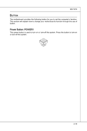
Press the button to turn-on or turn -off the system. 2-19 Power Button: POWER1 This power button is used to turn-on or turn -off the system. MS-7578 Button The motherboard provides the following button for you to change your motherboard's function through the use of button. This section will explain how to set the computer's function.
Press the button to turn-on or turn -off the system. 2-19 Power Button: POWER1 This power button is used to turn-on or turn -off the system. MS-7578 Button The motherboard provides the following button for you to change your motherboard's function through the use of button. This section will explain how to set the computer's function.
User Guide
Page 37
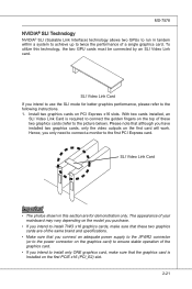
... model you purchase. • If you intend to install TWO x16 graphics cards, make sure that these two graphics cards (refer to the picture below). MS-7578 NVIDIA® SLI Technology NVIDIA® SLI (Scalable Link Interface) technology allows two GPUs to run in this technology, the two GPU cards must be...
... model you purchase. • If you intend to install TWO x16 graphics cards, make sure that these two graphics cards (refer to the picture below). MS-7578 NVIDIA® SLI Technology NVIDIA® SLI (Scalable Link Interface) technology allows two GPUs to run in this technology, the two GPU cards must be...
User Guide
Page 39
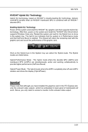
... on the Hybrid Icon in Performance mode and that although you only need to connect a monitor to provide higher performance (GeForce Boost) Hybrid-Power Mode - MS-7578 NVIDIA® Hybrid SLI Technology Hybrid SLI technology, based on NVIDIA®'s industry-leading SLI technology, delivers multi-GPU benefits when an NVIDIA® mainboard...
... on the Hybrid Icon in Performance mode and that although you only need to connect a monitor to provide higher performance (GeForce Boost) Hybrid-Power Mode - MS-7578 NVIDIA® Hybrid SLI Technology Hybrid SLI technology, based on NVIDIA®'s industry-leading SLI technology, delivers multi-GPU benefits when an NVIDIA® mainboard...
User Guide
Page 43
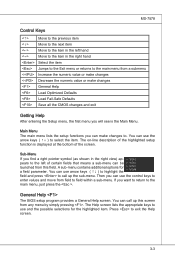
... can call up this field. Main Menu The main menu lists the setup functions you want to return to the main menu, just press the . MS-7578 Control Keys Move to the previous item Move to the next item Move to the item in the right hand Select the item Jumps to...
... can call up this field. Main Menu The main menu lists the setup functions you want to return to the main menu, just press the . MS-7578 Control Keys Move to the previous item Move to the next item Move to the item in the right hand Select the item Jumps to...


