
User Guide
Page 2
... with the instruction manual, may cause undesired operation ii These limits are designed to operate the equipment. Notice 2 Shielded interface cables and A.C. Micro-Star International MS-6712 This device complies with Part 15 of this device must accept any , must be used in which case the user will be required to part...
... with the instruction manual, may cause undesired operation ii These limits are designed to operate the equipment. Notice 2 Shielded interface cables and A.C. Micro-Star International MS-6712 This device complies with Part 15 of this device must accept any , must be used in which case the user will be required to part...

User Guide
Page 8
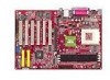
Getting Started Getting Started Thank you for optimal system efficiency. Designed to fit the advanced AMD® Athlon™, Athlon™ XP or Duron™ processors, the MS-6712 delivers a high performance and professional desktop platform solution. 1-1 The MS-6712 v1.X ATX mainboard is based on VIA® Apollo KT400A North Bridge & VT8235 South Bridge chipset for purchasing the MS-6712 v1.X ATX mainboard.
Getting Started Getting Started Thank you for optimal system efficiency. Designed to fit the advanced AMD® Athlon™, Athlon™ XP or Duron™ processors, the MS-6712 delivers a high performance and professional desktop platform solution. 1-1 The MS-6712 v1.X ATX mainboard is based on VIA® Apollo KT400A North Bridge & VT8235 South Bridge chipset for purchasing the MS-6712 v1.X ATX mainboard.
User Guide
Page 9
...On-Board IDE † An IDE controller on the VT8235 chipset provides IDE HDD/CD-ROM with 360K, 720K, 1.2M, 1.44M and 1-2 MS-6712 ATX Mainboard Mainboard Specifications CPU † Supports Socket A (Socket-462) for AMD® Athlon™/Athlon™ XP /Duron™ processors †...SDRAM * Please refer to Glossary: Recommended DDR400 Modules for details. Supports AGP 4X and AGP 8X † VIA® VT8235 South Bridge - msi.com.tw/program/products/mainboard/mbd/pro_mbd_cpu_support.php) Chipset † VIA® KT400A North Bridge - ACPI & PC2001 compliant enhanced power management - ...
...On-Board IDE † An IDE controller on the VT8235 chipset provides IDE HDD/CD-ROM with 360K, 720K, 1.2M, 1.44M and 1-2 MS-6712 ATX Mainboard Mainboard Specifications CPU † Supports Socket A (Socket-462) for AMD® Athlon™/Athlon™ XP /Duron™ processors †...SDRAM * Please refer to Glossary: Recommended DDR400 Modules for details. Supports AGP 4X and AGP 8X † VIA® VT8235 South Bridge - msi.com.tw/program/products/mainboard/mbd/pro_mbd_cpu_support.php) Chipset † VIA® KT400A North Bridge - ACPI & PC2001 compliant enhanced power management - ...

User Guide
Page 13
The 4 LEDs can use graphic signal display to RAM for fast booting. MS-6712 ATX Mainboard D-Bracket™ 2 (Optional) D-Bracket™ 2 is a USB bracket integrating four Diagnostic LEDs, which use the feature to detect if there are any problems or ...
The 4 LEDs can use graphic signal display to RAM for fast booting. MS-6712 ATX Mainboard D-Bracket™ 2 (Optional) D-Bracket™ 2 is a USB bracket integrating four Diagnostic LEDs, which use the feature to detect if there are any problems or ...

User Guide
Page 15
.... 2. Click the Audio tab. 3. The accompanying MSI DVD is a convenient tool to Appendix. MSI Reminds You... MSI DVD supports Dolby Digital format only. To view DTSformatted video, you must configure both the MSI DVD application and the audio codec's software utility. MS-6712 ATX Mainboard MSI DVD 5.1 Channel (Optional) The motherboard comes with MSI DVD: 1. To play DVD with 6-channel...
.... 2. Click the Audio tab. 3. The accompanying MSI DVD is a convenient tool to Appendix. MSI Reminds You... MSI DVD supports Dolby Digital format only. To view DTSformatted video, you must configure both the MSI DVD application and the audio codec's software utility. MS-6712 ATX Mainboard MSI DVD 5.1 Channel (Optional) The motherboard comes with MSI DVD: 1. To play DVD with 6-channel...
User Guide
Page 17
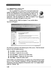
...the functions listed above, a "sorry" message is a tool used to detect and update your BIOS/drivers online so that you need to install the "MSI Live Update 2" application. z Live BIOS - z Live Driver - Updates the utilities online. To use the function, you don't need to search for...the Web site. Double click the "MSI Live Update 2" icon, and the following screen will appear on the update instructions, insert the companion CD and refer to start the update process. z Live VGA Driver - Updates the VGA BIOS online. MS-6712 ATX Mainboard Live BIOS™/Live Driver™...
...the functions listed above, a "sorry" message is a tool used to detect and update your BIOS/drivers online so that you need to install the "MSI Live Update 2" application. z Live BIOS - z Live Driver - Updates the utilities online. To use the function, you don't need to search for...the Web site. Double click the "MSI Live Update 2" icon, and the following screen will appear on the update instructions, insert the companion CD and refer to start the update process. z Live VGA Driver - Updates the VGA BIOS online. MS-6712 ATX Mainboard Live BIOS™/Live Driver™...

User Guide
Page 22
... Incorrect CPU placement X Press down firmly into the socket and can only fit in the correct orientation. 4. Pull the lever sideways away from the socket. MS-6712 ATX Mainboard CPU Installation Procedures for the gold arrow. If the CPU is properly and completely embedded into the socket. Press the CPU down the CPU...
... Incorrect CPU placement X Press down firmly into the socket and can only fit in the correct orientation. 4. Pull the lever sideways away from the socket. MS-6712 ATX Mainboard CPU Installation Procedures for the gold arrow. If the CPU is properly and completely embedded into the socket. Press the CPU down the CPU...
User Guide
Page 24
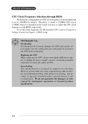
...tolerate such abnormal setting, while doing overclocking. Any attempt to operate beyond product specifications. 2-6 MSI Reminds You... Replacing the CPU While replacing the CPU, always turn off the ATX power supply or unplug the power supply's power cord from overheating. However, please make ... ensure the safety of the motherboard is installed on the board, you have to adjust the CPU clock frequency in Chapter 3. To set to 100MHz by inadequate operation or beyond product specifications is designed to support overclocking. MS-6712 ATX Mainboard CPU Clock Frequency Selection...
...tolerate such abnormal setting, while doing overclocking. Any attempt to operate beyond product specifications. 2-6 MSI Reminds You... Replacing the CPU While replacing the CPU, always turn off the ATX power supply or unplug the power supply's power cord from overheating. However, please make ... ensure the safety of the motherboard is installed on the board, you have to adjust the CPU clock frequency in Chapter 3. To set to 100MHz by inadequate operation or beyond product specifications is designed to support overclocking. MS-6712 ATX Mainboard CPU Clock Frequency Selection...

User Guide
Page 26
... 2 & 3) DIMM 3 S/D (Bank 4 & 5) Maximum System Memory Suppported Total Memory 64MB~1GB 64MB~1GB 64MB~1GB 64MB~3GB S: Single Side D: Double Side Installing DDR Modules 1. Volt Notch MSI Reminds You... Then push it in the socket. 2-8 The module will automatically close. You can install either single- The DDR DIMM has only one DIMM... center of the DIMM slot will only fit in any order to meet your own needs. Memory modules can be installed in the right orientation. 2. MS-6712 ATX Mainboard DIMM Module Combination Install at each side of module.
... 2 & 3) DIMM 3 S/D (Bank 4 & 5) Maximum System Memory Suppported Total Memory 64MB~1GB 64MB~1GB 64MB~1GB 64MB~3GB S: Single Side D: Double Side Installing DDR Modules 1. Volt Notch MSI Reminds You... Then push it in the socket. 2-8 The module will automatically close. You can install either single- The DDR DIMM has only one DIMM... center of the DIMM slot will only fit in any order to meet your own needs. Memory modules can be installed in the right orientation. 2. MS-6712 ATX Mainboard DIMM Module Combination Install at each side of module.

User Guide
Page 28
... 5 Mouse Clock 6 NC DESCRIPTION Mouse DATA No connection Ground +5V Mouse clock No connection 2-10 You can plug a PS/2® mouse directly into this connector. MS-6712 ATX Mainboard Back Panel The back panel provides the following connectors: Mouse Parallel Keyboard USB COM A COM B LAN (Optional) USB MIC L-in L-out Mouse Connector The...
... 5 Mouse Clock 6 NC DESCRIPTION Mouse DATA No connection Ground +5V Mouse clock No connection 2-10 You can plug a PS/2® mouse directly into this connector. MS-6712 ATX Mainboard Back Panel The back panel provides the following connectors: Mouse Parallel Keyboard USB COM A COM B LAN (Optional) USB MIC L-in L-out Mouse Connector The...

User Guide
Page 30
... 18 GND Ground 19 GND Ground 20 GND Ground 21 GND Ground 22 GND Ground 23 GND Ground 24 GND Ground 25 GND Ground 2-12 MS-6712 ATX Mainboard Parallel Port Connector: LPT1 The mainboard provides a 25-pin female centronic connector as LPT.
... 18 GND Ground 19 GND Ground 20 GND Ground 21 GND Ground 22 GND Ground 23 GND Ground 24 GND Ground 25 GND Ground 2-12 MS-6712 ATX Mainboard Parallel Port Connector: LPT1 The mainboard provides a 25-pin female centronic connector as LPT.

User Guide
Page 32
MS-6712 ATX Mainboard Serial Port Connectors: COM A & COM B The mainboard offers two 9-pin male DIN connectors as serial port COM A & COM B. Activity Indicators LAN Jack (RJ-45) ...
MS-6712 ATX Mainboard Serial Port Connectors: COM A & COM B The mainboard offers two 9-pin male DIN connectors as serial port COM A & COM B. Activity Indicators LAN Jack (RJ-45) ...

User Guide
Page 34
IDE1 can also connect a Master and a Slave drive. You must configure the second drive to Slave mode by setting its jumper. MSI Reminds You... You can connect up to Slave mode by hard disk vendors for future BIOS) and other devices. IDE 1 IDE 2 IDE1 (Primary ... hard disk documentation supplied by setting the jumper accordingly. IDE2 (Secondary IDE Connector) IDE2 can connect a Master and a Slave drive. Refer to IDE1. MS-6712 ATX Mainboard Hard Disk Connectors: IDE1 & IDE2 The mainboard has a 32-bit Enhanced PCI IDE and Ultra DMA 33/66/ 100/133 controller that provides PIO...
IDE1 can also connect a Master and a Slave drive. You must configure the second drive to Slave mode by setting its jumper. MSI Reminds You... You can connect up to Slave mode by hard disk vendors for future BIOS) and other devices. IDE 1 IDE 2 IDE1 (Primary ... hard disk documentation supplied by setting the jumper accordingly. IDE2 (Secondary IDE Connector) IDE2 can connect a Master and a Slave drive. Refer to IDE1. MS-6712 ATX Mainboard Hard Disk Connectors: IDE1 & IDE2 The mainboard has a 32-bit Enhanced PCI IDE and Ultra DMA 33/66/ 100/133 controller that provides PIO...

User Guide
Page 36
JFP2 Pin Definition PIN SIGNAL 1 GND 3 SLED 5 PLED 7 NC PIN SIGNAL 2 SPK- 4 BUZ+ 6 BUZ- 8 SPK+ MS-6712 ATX Mainboard Front Panel Connectors: JFP1 & JFP2 The mainboard provides two front panel connectors for electrical connection to GND Reserved. Do not use. JFP1 is compliant ...
JFP2 Pin Definition PIN SIGNAL 1 GND 3 SLED 5 PLED 7 NC PIN SIGNAL 2 SPK- 4 BUZ+ 6 BUZ- 8 SPK+ MS-6712 ATX Mainboard Front Panel Connectors: JFP1 & JFP2 The mainboard provides two front panel connectors for electrical connection to GND Reserved. Do not use. JFP1 is compliant ...
User Guide
Page 38
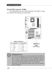
MS-6712 ATX Mainboard Front USB Connector: JUSB1 The mainboard provides one USB 2.0 pinheader. The USB 2.0 technology is supplied by Microsoft for more information. To use the USB 2.0 ... Manual. 2-20 JUSB1 Pin Definition Pin Description Pin Description 1 VCC 2 VCC 3 USB0- 4 USB1- 5 USB0+ 6 USB1+ 7 GND 8 GND 9 Key 10 USBOC 2 10 1 9 JUSB1 (USB 1.1/Intel spec) MSI Reminds You... If you have any problems regarding the USB 2.0 driver, please visit the Microsoft Web site for Windows® 2000 and XP. The JUSB1...
MS-6712 ATX Mainboard Front USB Connector: JUSB1 The mainboard provides one USB 2.0 pinheader. The USB 2.0 technology is supplied by Microsoft for more information. To use the USB 2.0 ... Manual. 2-20 JUSB1 Pin Definition Pin Description Pin Description 1 VCC 2 VCC 3 USB0- 4 USB1- 5 USB0+ 6 USB1+ 7 GND 8 GND 9 Key 10 USBOC 2 10 1 9 JUSB1 (USB 1.1/Intel spec) MSI Reminds You... If you have any problems regarding the USB 2.0 driver, please visit the Microsoft Web site for Windows® 2000 and XP. The JUSB1...

User Guide
Page 40
The two SPDIF jacks support SPDIF output only. MS-6712 ATX Mainboard S-Bracket Connector: JSP3 The connector allows you need to remove the plug from the jack first. To attach the fiber-optic cable to optical ...
The two SPDIF jacks support SPDIF output only. MS-6712 ATX Mainboard S-Bracket Connector: JSP3 The connector allows you need to remove the plug from the jack first. To attach the fiber-optic cable to optical ...

User Guide
Page 42
... system will be short. You must enter the BIOS utility and clear the record. To clear the warning, you to connect to IrDA Infrared module. MS-6712 ATX Mainboard IrDA Infrared Module Header: JIR1 The connector allows you must configure the setting through the BIOS setup to a 2-pin chassis switch. GND 2 CINTRU 1 JCI1...
... system will be short. You must enter the BIOS utility and clear the record. To clear the warning, you to connect to IrDA Infrared module. MS-6712 ATX Mainboard IrDA Infrared Module Header: JIR1 The connector allows you must configure the setting through the BIOS setup to a 2-pin chassis switch. GND 2 CINTRU 1 JCI1...

User Guide
Page 44
... of jumpers. This section will damage the mainboard. 2-26 You can automatically boot OS every time it will explain how to change your motherboard's function through the use the JBAT1 (Clear CMOS Jumper ) to clear data. If you to set the computer's function. Avoid clearing...clear the data: 3 3 1 Keep Data 1 Clear Data 3 1 JBAT1 MSI Reminds You... it is off. With the CMOS RAM, the system can clear CMOS by shorting 2-3 pin while the system is turned on. MS-6712 ATX Mainboard Jumpers The motherboard provides the following jumpers for you want to clear the system configuration...
... of jumpers. This section will damage the mainboard. 2-26 You can automatically boot OS every time it will explain how to change your motherboard's function through the use the JBAT1 (Clear CMOS Jumper ) to clear data. If you to set the computer's function. Avoid clearing...clear the data: 3 3 1 Keep Data 1 Clear Data 3 1 JBAT1 MSI Reminds You... it is off. With the CMOS RAM, the system can clear CMOS by shorting 2-3 pin while the system is turned on. MS-6712 ATX Mainboard Jumpers The motherboard provides the following jumpers for you want to clear the system configuration...

User Guide
Page 46
MS-6712 ATX Mainboard PCI Interrupt Request Routing The IRQ, acronym of interrupt request line and pronounced I-R-Q, are typically connected to the microprocessor. The PCI IRQ pins are hardware lines over which devices can send interrupt signals to the PCI bus INT A# ~ INT D# pins as follows: PCI Slot 1 PCI Slot 2 PCI Slot 3 PCI Slot 4 PCI Slot 5 PCI Slot 6 Order 1 INT A# INT B# INT C# INT D# INT B# INT C# Order 2 INT B# INT C# INT D# INT A# INT C# INT D# Order 3 INT C# INT D# INT A# INT B# INT D# INT A# Order 4 INT D# INT A# INT B# INT C# INT A# INT B# 2-28
MS-6712 ATX Mainboard PCI Interrupt Request Routing The IRQ, acronym of interrupt request line and pronounced I-R-Q, are typically connected to the microprocessor. The PCI IRQ pins are hardware lines over which devices can send interrupt signals to the PCI bus INT A# ~ INT D# pins as follows: PCI Slot 1 PCI Slot 2 PCI Slot 3 PCI Slot 4 PCI Slot 5 PCI Slot 6 Order 1 INT A# INT B# INT C# INT D# INT B# INT C# Order 2 INT B# INT C# INT D# INT A# INT C# INT D# Order 3 INT C# INT D# INT A# INT B# INT D# INT A# Order 4 INT D# INT A# INT B# INT C# INT A# INT B# 2-28
User Guide
Page 48
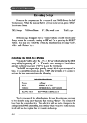
... allowed to the following. The system will still use the original first boot device to boot up. 3-2 The selection will list all the bootable devices. MS-6712 ATX Mainboard Entering Setup Power on the screen, press to trigger the boot menu. When the message below appears on the system, it OFF and On...
... allowed to the following. The system will still use the original first boot device to boot up. 3-2 The selection will list all the bootable devices. MS-6712 ATX Mainboard Entering Setup Power on the screen, press to trigger the boot menu. When the message below appears on the system, it OFF and On...


