User Guide
Page 5
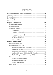
Getting Started 1-1 Mainboard Specifications 1-2 Mainboard Layout 1-4 MSI Special Features 1-5 Live Monitor 1-5 D-Bracket™ 2 (Optional 1-6 MSI DVD 5.1 Channel (Optional 1-8 LiveBIOS™/Live Driver 1-10 CPU Thermal Protection 1-11 S-Bracket (Optional 1-11 Chapter 2. Hardware Setup 2-1 Quick Components Guide 2-2 Central Processing Unit: CPU 2-3 ...
Getting Started 1-1 Mainboard Specifications 1-2 Mainboard Layout 1-4 MSI Special Features 1-5 Live Monitor 1-5 D-Bracket™ 2 (Optional 1-6 MSI DVD 5.1 Channel (Optional 1-8 LiveBIOS™/Live Driver 1-10 CPU Thermal Protection 1-11 S-Bracket (Optional 1-11 Chapter 2. Hardware Setup 2-1 Quick Components Guide 2-2 Central Processing Unit: CPU 2-3 ...

User Guide
Page 8
Getting Started Getting Started Thank you for optimal system efficiency. Designed to fit the advanced AMD® Athlon™, Athlon™ XP or Duron™ processors, the MS-6712 delivers a high performance and professional desktop platform solution. 1-1 The MS-6712 v1.X ATX mainboard is based on VIA® Apollo KT400A North Bridge & VT8235 South Bridge chipset for purchasing the MS-6712 v1.X ATX mainboard.
Getting Started Getting Started Thank you for optimal system efficiency. Designed to fit the advanced AMD® Athlon™, Athlon™ XP or Duron™ processors, the MS-6712 delivers a high performance and professional desktop platform solution. 1-1 The MS-6712 v1.X ATX mainboard is based on VIA® Apollo KT400A North Bridge & VT8235 South Bridge chipset for purchasing the MS-6712 v1.X ATX mainboard.
User Guide
Page 9
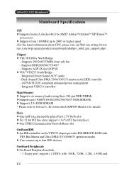
... 33/66/100/133 master mode EIDE controller - Integrated Direct Sound AC97 audio - ACPI & PC2001 compliant enhanced power management - MS-6712 ATX Mainboard Mainboard Specifications CPU † Supports Socket A (Socket-462) for details. Integrated USB 2.0 controller Main Memory † Supports six memory banks using... † On-Board Peripherals include: - 1 floppy port supports 2 FDDs with 360K, 720K, 1.2M, 1.44M and 1-2 msi.com.tw/program/products/mainboard/mbd/pro_mbd_cpu_support.php) Chipset † VIA® KT400A North Bridge - Supports 200/266/333MHz front side bus -
... 33/66/100/133 master mode EIDE controller - Integrated Direct Sound AC97 audio - ACPI & PC2001 compliant enhanced power management - MS-6712 ATX Mainboard Mainboard Specifications CPU † Supports Socket A (Socket-462) for details. Integrated USB 2.0 controller Main Memory † Supports six memory banks using... † On-Board Peripherals include: - 1 floppy port supports 2 FDDs with 360K, 720K, 1.2M, 1.44M and 1-2 msi.com.tw/program/products/mainboard/mbd/pro_mbd_cpu_support.php) Chipset † VIA® KT400A North Bridge - Supports 200/266/333MHz front side bus -

User Guide
Page 10
... provides "Plug & Play" BIOS which detects the peripheral devices and expansion cards of the board automatically. † The mainboard provides a Desktop Management Interface (DMI) function which records your mainboard specifications. Dimension †ATX Form Factor: 30.5 cm (L) x 21 cm (W) Mounting † 6 mounting holes Others † Suspend to RAM/Disk (S3/S4) †PC2001...
... provides "Plug & Play" BIOS which detects the peripheral devices and expansion cards of the board automatically. † The mainboard provides a Desktop Management Interface (DMI) function which records your mainboard specifications. Dimension †ATX Form Factor: 30.5 cm (L) x 21 cm (W) Mounting † 6 mounting holes Others † Suspend to RAM/Disk (S3/S4) †PC2001...

User Guide
Page 13
...feature is a USB bracket integrating four Diagnostic LEDs, which use the feature to detect if there are any problems or failures. MS-6712 ATX Mainboard D-Bracket™ 2 (Optional) D-Bracket™ 2 is very useful for overclocking users. The 4 LEDs can use graphic signal display...that fail the system, such as VGA, RAM or other failures. D-Bracket™ 2 supports both USB 1.1 & 2.0 spec. D-Bracket™ 2 for mainboard with bluetooth connector (1 port) 1 2 3 4 D-Bracket™ 2 for fast booting. Testing VGA BIOS - Initializing Keyboard Controller. This will hang here...
...feature is a USB bracket integrating four Diagnostic LEDs, which use the feature to detect if there are any problems or failures. MS-6712 ATX Mainboard D-Bracket™ 2 (Optional) D-Bracket™ 2 is very useful for overclocking users. The 4 LEDs can use graphic signal display...that fail the system, such as VGA, RAM or other failures. D-Bracket™ 2 supports both USB 1.1 & 2.0 spec. D-Bracket™ 2 for mainboard with bluetooth connector (1 port) 1 2 3 4 D-Bracket™ 2 for fast booting. Testing VGA BIOS - Initializing Keyboard Controller. This will hang here...

User Guide
Page 15
... (6-channel audio) operation. For information on this button from the control panel of MSI DVD. 2. Click the Audio tab. 3. MS-6712 ATX Mainboard MSI DVD 5.1 Channel (Optional) The motherboard comes with 6-channel audio output, you should convert it to enable 6-channel support with MSI DVD: 1. Using 4or 6-Channel Audio Function. Select 6 speaker mode (5.1 channel). The accompanying...
... (6-channel audio) operation. For information on this button from the control panel of MSI DVD. 2. Click the Audio tab. 3. MS-6712 ATX Mainboard MSI DVD 5.1 Channel (Optional) The motherboard comes with 6-channel audio output, you should convert it to enable 6-channel support with MSI DVD: 1. Using 4or 6-Channel Audio Function. Select 6 speaker mode (5.1 channel). The accompanying...
User Guide
Page 17
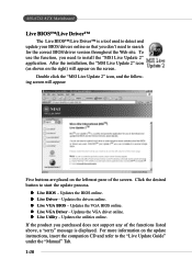
MS-6712 ATX Mainboard Live BIOS™/Live Driver™ The Live BIOS™/Live Driver™ is displayed. ...does not support any of the screen. Click the desired button to install the "MSI Live Update 2" application. Updates the VGA driver online. After the installation, the "MSI Live Update 2" icon (as shown on the right) will appear: Five buttons are... placed on the screen. Double click the "MSI Live Update 2" icon, and the following screen will appear on the leftmost pane of the functions listed above, ...
MS-6712 ATX Mainboard Live BIOS™/Live Driver™ The Live BIOS™/Live Driver™ is displayed. ...does not support any of the screen. Click the desired button to install the "MSI Live Update 2" application. Updates the VGA driver online. After the installation, the "MSI Live Update 2" icon (as shown on the right) will appear: Five buttons are... placed on the screen. Double click the "MSI Live Update 2" icon, and the following screen will appear on the leftmost pane of the functions listed above, ...

User Guide
Page 19
Also, it provides the instructions on the mainboard. While doing the installation, be careful in holding the components and follow the installation procedures. 2-1 Hardware Setup Hardware Setup This chapter tells you how to install the CPU, memory modules, and expansion cards, as well as how to setup the jumpers on connecting the peripheral devices, such as the mouse, keyboard, etc.
Also, it provides the instructions on the mainboard. While doing the installation, be careful in holding the components and follow the installation procedures. 2-1 Hardware Setup Hardware Setup This chapter tells you how to install the CPU, memory modules, and expansion cards, as well as how to setup the jumpers on connecting the peripheral devices, such as the mouse, keyboard, etc.

User Guide
Page 21
Hardware Setup Central Processing Unit: CPU The mainboard supports AMD® Athlon™, Athlon™ XP and Duron™ processors in the specified thermal requirements. If you do not find the heat sink ... processor and ensuring reliable operation. If you are needed to prevent overheating. AMD Athlon™/Duron™/Athlon™ XP processor with each other. The mainboard uses a CPU socket called Socket A for CPU As processor technology pushes to faster speeds and higher performance, thermal management becomes increasingly crucial when building computer...
Hardware Setup Central Processing Unit: CPU The mainboard supports AMD® Athlon™, Athlon™ XP and Duron™ processors in the specified thermal requirements. If you do not find the heat sink ... processor and ensuring reliable operation. If you are needed to prevent overheating. AMD Athlon™/Duron™/Athlon™ XP processor with each other. The mainboard uses a CPU socket called Socket A for CPU As processor technology pushes to faster speeds and higher performance, thermal management becomes increasingly crucial when building computer...

User Guide
Page 22
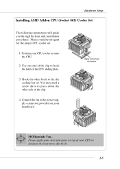
... pressing tightly on top of the correct installation procedures may cause permanent damages to a 90degree angle. 3. Make sure to raise the lever up to your mainboard. 5. Look for Socket 462 1. Please turn off the power and unplug the power cord before installing the CPU. 2. Press the CPU down the CPU Close...
... pressing tightly on top of the correct installation procedures may cause permanent damages to a 90degree angle. 3. Make sure to raise the lever up to your mainboard. 5. Look for Socket 462 1. Please turn off the power and unplug the power cord before installing the CPU. 2. Press the CPU down the CPU Close...
User Guide
Page 23
... the heat sink installation procedures. You may need a screw drive to fix the cooling fan set onto the CPU. 2. Please apply some heat sink paste MSI Reminds You... Please consult your CPU cooler set . Use one end of the clip to the power supply connector provided on top of the CPU...
... the heat sink installation procedures. You may need a screw drive to fix the cooling fan set onto the CPU. 2. Please apply some heat sink paste MSI Reminds You... Please consult your CPU cooler set . Use one end of the clip to the power supply connector provided on top of the CPU...
User Guide
Page 24
... are able to tolerate such abnormal setting, while doing overclocking. Any attempt to operate beyond product specifications. 2-6 MSI Reminds You... Overclocking This motherboard is not recommended. To set to 100MHz by inadequate operation or beyond product specifications is designed to support overclocking.... CPU from grounded outlet first to ensure the safety of the motherboard is installed on the board, you have to adjust the CPU clock frequency in Chapter 3. MS-6712 ATX Mainboard CPU Clock Frequency Selection through BIOS The hardware configuration for the installed...
... are able to tolerate such abnormal setting, while doing overclocking. Any attempt to operate beyond product specifications. 2-6 MSI Reminds You... Overclocking This motherboard is not recommended. To set to 100MHz by inadequate operation or beyond product specifications is designed to support overclocking.... CPU from grounded outlet first to ensure the safety of the motherboard is installed on the board, you have to adjust the CPU clock frequency in Chapter 3. MS-6712 ATX Mainboard CPU Clock Frequency Selection through BIOS The hardware configuration for the installed...

User Guide
Page 25
... by SDR SDRAM. You can install PC3200/DDR400, PC2700/DDR333, PC2100/ DDR266 or PC1600/DDR200 modules on the DDR DIMM slots. Hardware Setup Memory The mainboard provides 3 slots for high performance PC, workstations and servers. 2-7 It uses 2.5 volts as opposed to 3GB. Please note that the...
... by SDR SDRAM. You can install PC3200/DDR400, PC2700/DDR333, PC2100/ DDR266 or PC1600/DDR200 modules on the DDR DIMM slots. Hardware Setup Memory The mainboard provides 3 slots for high performance PC, workstations and servers. 2-7 It uses 2.5 volts as opposed to 3GB. Please note that the...

User Guide
Page 26
... close. You can barely see the golden finger if the module is deeply inserted in the socket. 3. MS-6712 ATX Mainboard DIMM Module Combination Install at each side of module. Volt Notch MSI Reminds You... Insert the DIMM memory module vertically into the DIMM slot. You can be installed in the right orientation...
... close. You can barely see the golden finger if the module is deeply inserted in the socket. 3. MS-6712 ATX Mainboard DIMM Module Combination Install at each side of module. Volt Notch MSI Reminds You... Insert the DIMM memory module vertically into the DIMM slot. You can be installed in the right orientation...

User Guide
Page 27
... power supply is inserted in the proper orientation and the pins are aligned. To connect to ensure that all components are installed properly to the ATX power supply, make sure that no damage will be caused. Then push down the power supply firmly into the connector. 11 1 20 10 ... 6 5V 16 7 GND 17 8 PW_OK 18 9 5V_SB 19 10 12V 20 SIGNAL 3.3V -12V GND PS_ON GND GND GND -5V 5V 5V 2-9 ATX 20-Pin Power Connector: JWR1 This connector allows you to connect to an ATX power supply. Hardware Setup Power Supply The mainboard supports ATX power supply for the power system.
... power supply is inserted in the proper orientation and the pins are aligned. To connect to ensure that all components are installed properly to the ATX power supply, make sure that no damage will be caused. Then push down the power supply firmly into the connector. 11 1 20 10 ... 6 5V 16 7 GND 17 8 PW_OK 18 9 5V_SB 19 10 12V 20 SIGNAL 3.3V -12V GND PS_ON GND GND GND -5V 5V 5V 2-9 ATX 20-Pin Power Connector: JWR1 This connector allows you to connect to an ATX power supply. Hardware Setup Power Supply The mainboard supports ATX power supply for the power system.

User Guide
Page 28
... Definition PIN SIGNAL 1 Mouse DATA 2 NC 3 GND 4 VCC 5 Mouse Clock 6 NC DESCRIPTION Mouse DATA No connection Ground +5V Mouse clock No connection 2-10 MS-6712 ATX Mainboard Back Panel The back panel provides the following connectors: Mouse Parallel Keyboard USB COM A COM B LAN (Optional) USB MIC L-in L-out Mouse Connector The...
... Definition PIN SIGNAL 1 Mouse DATA 2 NC 3 GND 4 VCC 5 Mouse Clock 6 NC DESCRIPTION Mouse DATA No connection Ground +5V Mouse clock No connection 2-10 MS-6712 ATX Mainboard Back Panel The back panel provides the following connectors: Mouse Parallel Keyboard USB COM A COM B LAN (Optional) USB MIC L-in L-out Mouse Connector The...

User Guide
Page 29
... Definition PIN SIGNAL DESCRIPTION 1 Keyboard DATA Keyboard DATA 2 NC No connection 3 GND Ground 4 VCC +5V 5 Keyboard Clock Keyboard clock 6 NC No connection USB Connectors The mainboard provides a UHCI (Universal Host Controller Interface) Universal Serial Bus root for attaching a PS/2® keyboard. Hardware Setup Keyboard Connector The...
... Definition PIN SIGNAL DESCRIPTION 1 Keyboard DATA Keyboard DATA 2 NC No connection 3 GND Ground 4 VCC +5V 5 Keyboard Clock Keyboard clock 6 NC No connection USB Connectors The mainboard provides a UHCI (Universal Host Controller Interface) Universal Serial Bus root for attaching a PS/2® keyboard. Hardware Setup Keyboard Connector The...

User Guide
Page 30
... Ground 19 GND Ground 20 GND Ground 21 GND Ground 22 GND Ground 23 GND Ground 24 GND Ground 25 GND Ground 2-12 MS-6712 ATX Mainboard Parallel Port Connector: LPT1 The mainboard provides a 25-pin female centronic connector as LPT.
... Ground 19 GND Ground 20 GND Ground 21 GND Ground 22 GND Ground 23 GND Ground 24 GND Ground 25 GND Ground 2-12 MS-6712 ATX Mainboard Parallel Port Connector: LPT1 The mainboard provides a 25-pin female centronic connector as LPT.

User Guide
Page 32
MS-6712 ATX Mainboard Serial Port Connectors: COM A & COM B The mainboard offers two 9-pin male DIN connectors as serial port COM A & COM B. The ports are 16550A high speed communication ports that allows your computer to be ... Out or Transmit Data Data Terminal Ready) Ground Data Set Ready Request To Send Clear To Send Ring Indicate RJ-45 LAN Jack (Optional) The mainboard provides a RJ-45 connector that send/receive 16 bytes FIFOs. Activity Indicators LAN Jack (RJ-45) Pin Signal 1 TDP 2 TDN 3 RDP 4 NC 5 NC 6 RDN 7 NC...
MS-6712 ATX Mainboard Serial Port Connectors: COM A & COM B The mainboard offers two 9-pin male DIN connectors as serial port COM A & COM B. The ports are 16550A high speed communication ports that allows your computer to be ... Out or Transmit Data Data Terminal Ready) Ground Data Set Ready Request To Send Clear To Send Ring Indicate RJ-45 LAN Jack (Optional) The mainboard provides a RJ-45 connector that send/receive 16 bytes FIFOs. Activity Indicators LAN Jack (RJ-45) Pin Signal 1 TDP 2 TDN 3 RDP 4 NC 5 NC 6 RDN 7 NC...

User Guide
Page 33
Hardware Setup Connectors The mainboard provides connectors to connect to FDD, IDE HDD, case, modem, LAN, USB Ports, IR module and CPU/System FAN. FDD1 2-15 Floppy Disk Drive Connector: FDD1 The mainboard provides a standard floppy disk drive connector that supports 360K, 720K, 1.2M, 1.44M and 2.88M floppy disk types.
Hardware Setup Connectors The mainboard provides connectors to connect to FDD, IDE HDD, case, modem, LAN, USB Ports, IR module and CPU/System FAN. FDD1 2-15 Floppy Disk Drive Connector: FDD1 The mainboard provides a standard floppy disk drive connector that supports 360K, 720K, 1.2M, 1.44M and 2.88M floppy disk types.


