
User Guide
Page 2
...are the properties of purchase or local distributor. Netware® is a registered trademark of Microsoft Corporation. Visit the MSI website for FAQ, technical guide, BIOS updates, driver updates, and other countries. AMI® is a registered trademark of Intel Corporation. Intel® .... Award® is a registered trademark of International Business Machines Corporation. func=service Contact our technical staff at: http://ocss.msi.com.tw ii AMD, Athlon™, Athlon™ XP, Thoroughbred™, and Duron™ are registered trademarks of Phoenix Technologies...
...are the properties of purchase or local distributor. Netware® is a registered trademark of Microsoft Corporation. Visit the MSI website for FAQ, technical guide, BIOS updates, driver updates, and other countries. AMI® is a registered trademark of Intel Corporation. Intel® .... Award® is a registered trademark of International Business Machines Corporation. func=service Contact our technical staff at: http://ocss.msi.com.tw ii AMD, Athlon™, Athlon™ XP, Thoroughbred™, and Duron™ are registered trademarks of Phoenix Technologies...

User Guide
Page 8
... ...2-6 Power Supply ...2-8 Back Panel ...2-9 Connectors ...2-11 Jumpers ...2-18 Buttons ...2-19 Switc h ...2-20 Slots ...2-21 Chapter 3 BIOS Setup 3-1 Entering Setup ...3-2 The Main Menu ...3-4 Standard CMOS Features 3-6 Advanced BIOS Features 3-8 Integrated Peripherals 3-11 Power Management Setup 3-13 H/W Monitor ...3-16 BIOS Setting Password 3-17 Cell Menu ...3-18 Load Fail-Safe/ Optimized Defaults 3-21 viii CONTENTS Copyright...
... ...2-6 Power Supply ...2-8 Back Panel ...2-9 Connectors ...2-11 Jumpers ...2-18 Buttons ...2-19 Switc h ...2-20 Slots ...2-21 Chapter 3 BIOS Setup 3-1 Entering Setup ...3-2 The Main Menu ...3-4 Standard CMOS Features 3-6 Advanced BIOS Features 3-8 Integrated Peripherals 3-11 Power Management Setup 3-13 H/W Monitor ...3-16 BIOS Setting Password 3-17 Cell Menu ...3-18 Load Fail-Safe/ Optimized Defaults 3-21 viii CONTENTS Copyright...

User Guide
Page 19
.... 1. Hardware Setup Installing AMD Socket AM2+/AM2 CPU Cooler Set W hen you are for demonstration of the CPU/ cooler installation only. Mainboard photos shown in BIOS (Chapter 3). 2. Fixed Lever 3. Attach the CPU Fan cable to prevent overheating. Important 1. Hook one end of the retention mechanism. The appearance of your dealer to...
.... 1. Hardware Setup Installing AMD Socket AM2+/AM2 CPU Cooler Set W hen you are for demonstration of the CPU/ cooler installation only. Mainboard photos shown in BIOS (Chapter 3). 2. Fixed Lever 3. Attach the CPU Fan cable to prevent overheating. Important 1. Hook one end of the retention mechanism. The appearance of your dealer to...
User Guide
Page 26
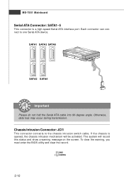
... SATA3 SATA5 SATA2 SATA4 Important Please do not fold the Serial ATA cable into 90-degree angle. To clear the warning, you must enter the BIOS utility and clear the record. GND 1 CINTRU 2-12 Chassis Intrusion Connector: JCI1 This connector connects to one Serial ATA device. Each connector can connect to...
... SATA3 SATA5 SATA2 SATA4 Important Please do not fold the Serial ATA cable into 90-degree angle. To clear the warning, you must enter the BIOS utility and clear the record. GND 1 CINTRU 2-12 Chassis Intrusion Connector: JCI1 This connector connects to one Serial ATA device. Each connector can connect to...

User Guide
Page 35
... 2.0x 16 supports up to a single display for blisteringly-fast frame rates. Meanwhile, read the documentation for the expansion card, such as jumpers, switches or BIOS configuration. Restart the system and wait for the ATI icon to configure any necessary hardware or software settings for the expansion card to show in...
... 2.0x 16 supports up to a single display for blisteringly-fast frame rates. Meanwhile, read the documentation for the expansion card, such as jumpers, switches or BIOS configuration. Restart the system and wait for the ATI icon to configure any necessary hardware or software settings for the expansion card to show in...
User Guide
Page 37
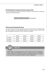
The PCI IRQ pins are hardware lines over which devices can send interrupt signals to the PCI bus pins as jumpers, switches or BIOS configuration. 2-23 Hardware Setup PCI (Peripheral Component Interconnect) Slot The PCI slot supports LAN card, SCSI card, USB card, and other add-on cards that ...
The PCI IRQ pins are hardware lines over which devices can send interrupt signals to the PCI bus pins as jumpers, switches or BIOS configuration. 2-23 Hardware Setup PCI (Peripheral Component Interconnect) Slot The PCI slot supports LAN card, SCSI card, USB card, and other add-on cards that ...
User Guide
Page 38
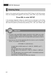
You may need to run the Setup program when: ² An error message appears on the BIOS Setup program and allows you to run SETUP. ² You want to configure the system for customized features. 3-1 Chapter 3 BIOS Setup BIOS Setup This chapter provides information on the screen during the system booting up, and requests you to change the default settings for optimum use.
You may need to run the Setup program when: ² An error message appears on the BIOS Setup program and allows you to run SETUP. ² You want to configure the system for customized features. 3-1 Chapter 3 BIOS Setup BIOS Setup This chapter provides information on the screen during the system booting up, and requests you to change the default settings for optimum use.
User Guide
Page 39
... described in the format: A7551AMS V1.0 080108 where: 1st digit refers to BIOS maker as A = AMI, W = AWARD, and P = PHOENIX. 2nd - 5th digit refers to the model number. 6th digit refers to the chipset as I = Intel, N = nVidia, A = AMD and V = ... 1. Upon boot-up, the 1st line appearing after the memory count is usually in this BIOS was released. 3-2 You may be slightly different from the latest BIOS and should be held for better system performance. It is the BIOS version. The items under continuous update for reference only. 2. W hen the message below appears...
... described in the format: A7551AMS V1.0 080108 where: 1st digit refers to BIOS maker as A = AMI, W = AWARD, and P = PHOENIX. 2nd - 5th digit refers to the model number. 6th digit refers to the chipset as I = Intel, N = nVidia, A = AMD and V = ... 1. Upon boot-up, the 1st line appearing after the memory count is usually in this BIOS was released. 3-2 You may be slightly different from the latest BIOS and should be held for better system performance. It is the BIOS version. The items under continuous update for reference only. 2. W hen the message below appears...
User Guide
Page 40
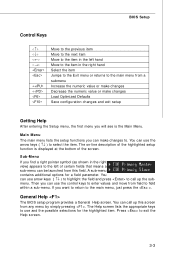
.... You can use and the possible selections for a field parameter. Then you want to return to the main menu, just press the . General Help The BIOS setup program provides a General Help screen. The Help screen lists the appropriate keys to use the control keys to enter values and move from field... can use the arrow keys ( ↑↓ ) to exit the Help screen. 3-3 Sub-M enu If you can be launched from any menu by simply pressing . BIOS Setup Control Keys Enter> Move to the previous item Move to the next item Move to the item in the left hand Move to the...
.... You can use and the possible selections for a field parameter. Then you want to return to the main menu, just press the . General Help The BIOS setup program provides a General Help screen. The Help screen lists the appropriate keys to use the control keys to enter values and move from field... can use the arrow keys ( ↑↓ ) to exit the Help screen. 3-3 Sub-M enu If you can be launched from any menu by simply pressing . BIOS Setup Control Keys Enter> Move to the previous item Move to the next item Move to the item in the left hand Move to the...
User Guide
Page 41
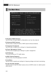
... Use this menu to load the default values set the password for power management. Power Management Setup Use this menu to set by the BIOS vendor for frequency/voltage control and overclocking. Integrated Peripherals Use this menu to specify your settings for stable system performance. 3-4 MS-7551 Mainboard The Main ... items of AMI® special enhanced features. Cell Menu Use this menu to specify your settings for basic system configurations, such as time, date etc. BIOS Setting Password Use this menu for integrated peripherals.
... Use this menu to load the default values set the password for power management. Power Management Setup Use this menu to set by the BIOS vendor for frequency/voltage control and overclocking. Integrated Peripherals Use this menu to specify your settings for stable system performance. 3-4 MS-7551 Mainboard The Main ... items of AMI® special enhanced features. Cell Menu Use this menu to specify your settings for basic system configurations, such as time, date etc. BIOS Setting Password Use this menu for integrated peripherals.

User Guide
Page 42
Exit Without Saving Abandon all changes and exit setup. 3-5 BIOS Setup Load Optimized Defaults Use this menu to CMOS and exit setup. Save & Exit Setup Save changes to load the default values set by the mainboard manufacturer specifically for optimal performance of the mainboard.
Exit Without Saving Abandon all changes and exit setup. 3-5 BIOS Setup Load Optimized Defaults Use this menu to CMOS and exit setup. Save & Exit Setup Save changes to load the default values set by the mainboard manufacturer specifically for optimal performance of the mainboard.
User Guide
Page 43
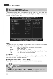
.... month The month from 1 to set the system to the date that you want (usually the current time). year The year can be adjusted by BIOS. The time format is . Date This allows you to set the system time that you want (usually the current date). IDE Primary Master/ Slave, SATA1...
.... month The month from 1 to set the system to the date that you want (usually the current time). year The year can be adjusted by BIOS. The time format is . Date This allows you to set the system time that you want (usually the current date). IDE Primary Master/ Slave, SATA1...
User Guide
Page 44
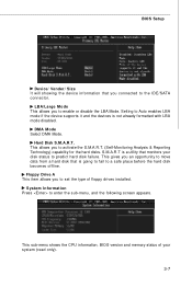
... and the devices is going to fail to predict hard disk failure. Hard Disk S.M.A.R.T. This sub-menu shows the CPU information, BIOS version and memory status of floppy drives installed. BIOS Setup Device/ Vender/ Size It will showing the device information that you connected to set the type of your disk status...
... and the devices is going to fail to predict hard disk failure. Hard Disk S.M.A.R.T. This sub-menu shows the CPU information, BIOS version and memory status of floppy drives installed. BIOS Setup Device/ Vender/ Size It will showing the device information that you connected to set the type of your disk status...
User Guide
Page 45
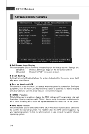
... vendor of your operating system. Setting to set the Num Lock status when the system is powered on the numeric keypad. MS-7551 Mainboard Advanced BIOS Features Full Screen Logo Display This item enables you to select which version to enable or disable the APIC (Advanced Programmable Interrupt Controller). Setting to...
... vendor of your operating system. Setting to set the Num Lock status when the system is powered on the numeric keypad. MS-7551 Mainboard Advanced BIOS Features Full Screen Logo Display This item enables you to select which version to enable or disable the APIC (Advanced Programmable Interrupt Controller). Setting to...
User Guide
Page 46
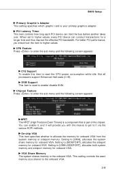
... device can enable it, and it via the various ACPI methods. You can hold the bus before another takes over. Setting to the onboard VGA. BIOS Setup Primary Graphic's Adapter This setting specifies which graphic card is part of the chipset. VGA Share Memory The system shares memory to [UMA], allocates...
... device can enable it, and it via the various ACPI methods. You can hold the bus before another takes over. Setting to the onboard VGA. BIOS Setup Primary Graphic's Adapter This setting specifies which graphic card is part of the chipset. VGA Share Memory The system shares memory to [UMA], allocates...
User Guide
Page 47
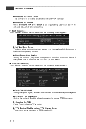
...] enables TPM (Trusted Platform Module) to the system. MS-7551 Mainboard Onboard VGA Over Clock This item is set the first/ second boot device where BIOS attempts to load the disk operating system. TPM Enable/Disable status, TPM Owner Status These items show the status of TPM (read only). 3-10
...] enables TPM (Trusted Platform Module) to the system. MS-7551 Mainboard Onboard VGA Over Clock This item is set the first/ second boot device where BIOS attempts to load the disk operating system. TPM Enable/Disable status, TPM Owner Status These items show the status of TPM (read only). 3-10
User Guide
Page 48
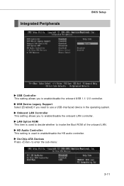
HD Audio Controller This setting is used to enter the sub-menu: 3-11 On-Chip ATA Devices Press to enable/disable the HD audio controller. Onboard LAN Controller This setting allows you need to enable/disable the onboard LAN controller. USB Device Legacy Support Select [Enabled] if you to use a USB-interfaced device in the operating system. Integrated Peripherals BIOS Setup USB Controller This setting allows you to invoke the Boot ROM of the onboard LAN. LAN Option ROM This item is used to decide whether to enable/disable the onboard USB 1.1/ 2.0 controller.
HD Audio Controller This setting is used to enter the sub-menu: 3-11 On-Chip ATA Devices Press to enable/disable the HD audio controller. Onboard LAN Controller This setting allows you need to enable/disable the onboard LAN controller. USB Device Legacy Support Select [Enabled] if you to use a USB-interfaced device in the operating system. Integrated Peripherals BIOS Setup USB Controller This setting allows you to invoke the Boot ROM of the onboard LAN. LAN Option ROM This item is used to decide whether to enable/disable the onboard USB 1.1/ 2.0 controller.
User Guide
Page 49
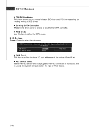
I /O port addresses of PS/2 device. 3-12 Set to enter the sub-menu: COM Port 1 This item specifies the base I /O Devices Press to [Auto], the system will auto detect the type of the onboard Serial Port. RAID Mode Use this item to IDE drives. MS-7551 Mainboard PCI IDE BusMaster This item allows you to enable/ disable BIOS to used PCI busmastering for reading/ writing to define the SATA mode. PS2 device select Select the PS/2 device which be pluged to enable or disable the SATA controller. On-Chip SATA Controller These items allow users to the PS/2 connector of mainbaord.
I /O port addresses of PS/2 device. 3-12 Set to enter the sub-menu: COM Port 1 This item specifies the base I /O Devices Press to [Auto], the system will auto detect the type of the onboard Serial Port. RAID Mode Use this item to IDE drives. MS-7551 Mainboard PCI IDE BusMaster This item allows you to enable/ disable BIOS to used PCI busmastering for reading/ writing to define the SATA mode. PS2 device select Select the PS/2 device which be pluged to enable or disable the SATA controller. On-Chip SATA Controller These items allow users to the PS/2 connector of mainbaord.
User Guide
Page 50
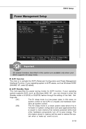
...remains powered while most other hardware components turn off to save energy. tem when a "wake up" event occurs. 3-13 If your BIOS supports S3 sleep mode. tings are available only when your operating system is lost (CPU or chipset) and hardware main- The information ...stored in memory will be used to activate the ACPI (Advanced Configuration and Power Management Interface) Function. Power Management Setup BIOS Setup Important S3-related functions described in this field. ACPI Function This item is a low power state. Set- tains all system context. ...
...remains powered while most other hardware components turn off to save energy. tem when a "wake up" event occurs. 3-13 If your BIOS supports S3 sleep mode. tings are available only when your operating system is lost (CPU or chipset) and hardware main- The information ...stored in memory will be used to activate the ACPI (Advanced Configuration and Power Management Interface) Function. Power Management Setup BIOS Setup Important S3-related functions described in this field. ACPI Function This item is a low power state. Set- tains all system context. ...

User Guide
Page 51
... not support the initialization feature, the display may work abnormally or not function after a power failure or interrupt occurs. MS-7551 Mainboard Re-Call VGA BIOS from S3 W hen ACPI Standby State is set the wake up the system from S3 (Suspend to initialize the VGA card. Resume From S3 By... will reboot after resuming from S3. Restore On AC Power Loss This item specifies whether your system will be defined by OS. Select [Enabled] allows BIOS to call VGABIOS to power on / off button. [Suspend] W hen you disable the function, but if the button is pressed for more than four ...
... not support the initialization feature, the display may work abnormally or not function after a power failure or interrupt occurs. MS-7551 Mainboard Re-Call VGA BIOS from S3 W hen ACPI Standby State is set the wake up the system from S3 (Suspend to initialize the VGA card. Resume From S3 By... will reboot after resuming from S3. Restore On AC Power Loss This item specifies whether your system will be defined by OS. Select [Enabled] allows BIOS to call VGABIOS to power on / off button. [Suspend] W hen you disable the function, but if the button is pressed for more than four ...


