User Guide
Page 2
Micro-Star International MS-6702 Tested to comply with the limits for compliance could void the user's authority to provide reasonable protection against harmful interference when the equipment is likely ...
Micro-Star International MS-6702 Tested to comply with the limits for compliance could void the user's authority to provide reasonable protection against harmful interference when the equipment is likely ...
User Guide
Page 8
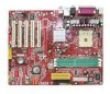
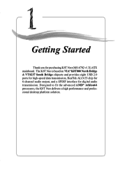
Designed to fit the advanced AMD® Athlon64 processors, the K8T Neo delivers a high performance and professional desktop platform solution. 1-1 Getting Started Getting Started Thank you for digital audio transmission. The K8T Neo is based on VIA® K8T800 North Bridge & VT8237 South Bridge chipsets and provides eight USB 2.0 ports for high-speed data transmission, RealTek ALC655 chip for 6-channel audio output, and a SPDIF interface for purchasing K8T Neo (MS-6702 v1.X) ATX mainboard. Getting Started Chapter 1.
Designed to fit the advanced AMD® Athlon64 processors, the K8T Neo delivers a high performance and professional desktop platform solution. 1-1 Getting Started Getting Started Thank you for digital audio transmission. The K8T Neo is based on VIA® K8T800 North Bridge & VT8237 South Bridge chipsets and provides eight USB 2.0 ports for high-speed data transmission, RealTek ALC655 chip for 6-channel audio output, and a SPDIF interface for purchasing K8T Neo (MS-6702 v1.X) ATX mainboard. Getting Started Chapter 1.
User Guide
Page 9
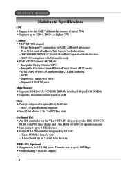
... - Integrated Faster Ethernet LPC - Can connect up to 2 serial ATA devices IEEE 1394 (Optional) h Supports up to 3200+, 3400+, or higher CPU Chipset h VIA® K8T800 chipset - MS-6702 ATX Mainboard Mainboard Specifications CPU h Supports 64-bit AMD® Athlon64 processor (Socket 754) h Supports up to 2 * 1394 ports. HyperTransportTM connection to 4 IDE devices...
... - Integrated Faster Ethernet LPC - Can connect up to 2 serial ATA devices IEEE 1394 (Optional) h Supports up to 3200+, 3400+, or higher CPU Chipset h VIA® K8T800 chipset - MS-6702 ATX Mainboard Mainboard Specifications CPU h Supports 64-bit AMD® Athlon64 processor (Socket 754) h Supports up to 2 * 1394 ports. HyperTransportTM connection to 4 IDE devices...
User Guide
Page 11
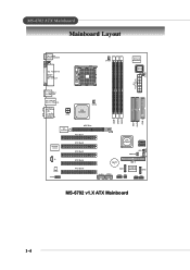
...K8T800 SFAN1 DDR 1 DDR 2 DDR 3 IDE 1 IDE 2 FDD 1 VIA VT6307 R e al Te k 8 110 S J4 Codec JAUD1 AGP Slot PCI Slot 1 PCI Slot 2 PCI Slot 3 PCI Slot 4 PCI Slot 5 VIA VT8237 SATA 1 SATA 2 JBAT1 JGS1 PW FA N 2 PW FA N 1 BATT + SER1 IDE 3 PROMISE PDC20378 SER2 JUSB1 JUSB2 JLED JIR1 JFP2 JFP1 MS-6702... v1.X ATX Mainboard 1-4 I n M:Line-Out B:Mic T: L i n e- MS-6702 ATX Mainboard Mainboard Layout Top : mouse Bottom: keyboard Top : Parallel P ort Bottom: 1394 port Mini 1394 port...
...K8T800 SFAN1 DDR 1 DDR 2 DDR 3 IDE 1 IDE 2 FDD 1 VIA VT6307 R e al Te k 8 110 S J4 Codec JAUD1 AGP Slot PCI Slot 1 PCI Slot 2 PCI Slot 3 PCI Slot 4 PCI Slot 5 VIA VT8237 SATA 1 SATA 2 JBAT1 JGS1 PW FA N 2 PW FA N 1 BATT + SER1 IDE 3 PROMISE PDC20378 SER2 JUSB1 JUSB2 JLED JIR1 JFP2 JFP1 MS-6702... v1.X ATX Mainboard 1-4 I n M:Line-Out B:Mic T: L i n e- MS-6702 ATX Mainboard Mainboard Layout Top : mouse Bottom: keyboard Top : Parallel P ort Bottom: 1394 port Mini 1394 port...
User Guide
Page 13
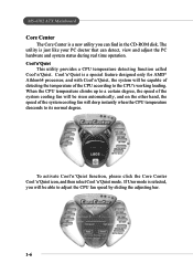
... select Cool'n'Quiet mode. If User mode is selected, you can detect, view and adjust the PC hardware and system status during real time operation. MS-6702 ATX Mainboard Core Center The Core Center is a new utility you will be able to adjust the CPU fan speed by sliding the adjusting bar. 1-6
... select Cool'n'Quiet mode. If User mode is selected, you can detect, view and adjust the PC hardware and system status during real time operation. MS-6702 ATX Mainboard Core Center The Core Center is a new utility you will be able to adjust the CPU fan speed by sliding the adjusting bar. 1-6
User Guide
Page 15
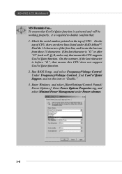
If the last character is required to "Enable." 3. Find the 13 characters of CPU, there are three lines listed under Power schemes. 1-8 MS-6702 ATX Mainboard MSI Reminds You... To ensure that Cool'n'Quiet function is activated and will be working properly, it is "O" or after "O" (such as P, Q, R, and so on the ...
If the last character is required to "Enable." 3. Find the 13 characters of CPU, there are three lines listed under Power schemes. 1-8 MS-6702 ATX Mainboard MSI Reminds You... To ensure that Cool'n'Quiet function is activated and will be working properly, it is "O" or after "O" (such as P, Q, R, and so on the ...
User Guide
Page 17
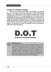
D.O.T Dynamic Overclocking Technology MSI Reminds You... When the motherboard detects CPU is still risky. Even though the Dynamic Overclocking Technology is more stable than manual overclocking, basically, it is running programs, and to lower ... incidentally, it will be powered only when users' PC need to overclocking regularly first. Usually the Dynamic Overclocking Technology will restore the default settings instead. MS-6702 ATX Mainboard Dynamic Overclocking Technology Dynamic Overclocking Technology is the automatic overclocking function.
D.O.T Dynamic Overclocking Technology MSI Reminds You... When the motherboard detects CPU is still risky. Even though the Dynamic Overclocking Technology is more stable than manual overclocking, basically, it is running programs, and to lower ... incidentally, it will be powered only when users' PC need to overclocking regularly first. Usually the Dynamic Overclocking Technology will restore the default settings instead. MS-6702 ATX Mainboard Dynamic Overclocking Technology Dynamic Overclocking Technology is the automatic overclocking function.
User Guide
Page 19
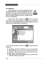
... - z FAQ - Double click this icon to install the "MSI Live Update 3" application. Provides a link to a database which contains various possible questions about MSI's products for the latest BIOS/drivers version on the right) will appear. MS-6702 ATX Mainboard Live Monitor™ The Live Monitor™ is any.... Allows you need immediately. z Exit - You can right-click the MSI Live Monitor icon to view the last search result if there ...
... - z FAQ - Double click this icon to install the "MSI Live Update 3" application. Provides a link to a database which contains various possible questions about MSI's products for the latest BIOS/drivers version on the right) will appear. MS-6702 ATX Mainboard Live Monitor™ The Live Monitor™ is any.... Allows you need immediately. z Exit - You can right-click the MSI Live Monitor icon to view the last search result if there ...
User Guide
Page 21
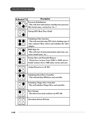
... Video Interface - Operating System Booting 1-14 BIOS Sign On - Assign Resources to 640K and extended memory above 1MB using various patterns. Initializing Floppy Drive Controller - MS-6702 ATX Mainboard D-Bracket™ 2 Description Processor Initialization 1 2 - Testing Base and Extended Memory - This will set low stack and boot via INT 19h. Thi will initialize...
... Video Interface - Operating System Booting 1-14 BIOS Sign On - Assign Resources to 640K and extended memory above 1MB using various patterns. Initializing Floppy Drive Controller - MS-6702 ATX Mainboard D-Bracket™ 2 Description Processor Initialization 1 2 - Testing Base and Extended Memory - This will set low stack and boot via INT 19h. Thi will initialize...
User Guide
Page 25
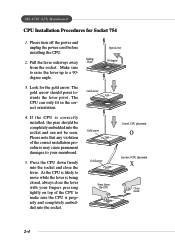
... towards the lever pivot. Please note that any violation of the CPU to move while the lever is properly and completely embedded into the socket. 2-4 MS-6702 ATX Mainboard CPU Installation Procedures for the gold arrow. Look for Socket 754 1. As the CPU is likely to make sure the CPU is being...
... towards the lever pivot. Please note that any violation of the CPU to move while the lever is properly and completely embedded into the socket. 2-4 MS-6702 ATX Mainboard CPU Installation Procedures for the gold arrow. Look for Socket 754 1. As the CPU is likely to make sure the CPU is being...
User Guide
Page 27
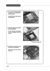
Locate the two screw holes of the clip to hook first. Hook one end of the mainboard. 4. Fix the retention mechanism and the backplate with two screws. 5. MS-6702 ATX Mainboard 3. Align the retention mechanism and the backplate. retention mechanism 2-6 Position the cooling set onto the retention mechanism. Turn over the mainboard again, and place the mainboard on the flat surface.
Locate the two screw holes of the clip to hook first. Hook one end of the mainboard. 4. Fix the retention mechanism and the backplate with two screws. 5. MS-6702 ATX Mainboard 3. Align the retention mechanism and the backplate. retention mechanism 2-6 Position the cooling set onto the retention mechanism. Turn over the mainboard again, and place the mainboard on the flat surface.
User Guide
Page 29
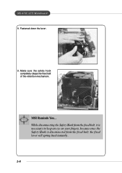
MS-6702 ATX Mainboard 8. While disconnecting the Safety Hook from the fixed bolt, it is necessary to keep an eye on your fingers, because once the Safety Hook is disconnected from the fixed bolt, the fixed lever will spring back instantly. 2-8 MSI Reminds You... Fastened down the lever. 9. Make sure the safety hook completely clasps the fixed bolt of the retention mechanism.
MS-6702 ATX Mainboard 8. While disconnecting the Safety Hook from the fixed bolt, it is necessary to keep an eye on your fingers, because once the Safety Hook is disconnected from the fixed bolt, the fixed lever will spring back instantly. 2-8 MSI Reminds You... Fastened down the lever. 9. Make sure the safety hook completely clasps the fixed bolt of the retention mechanism.
User Guide
Page 31
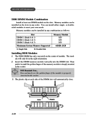
... 0 & 1) DIMM 2 (Bank 2 & 3) DIMM 3 (Bank 4 & 5) Maximum System Memory Supported S: Single Side D: Double Side Memory Module S/D S/D S/D 64MB~2GB Installing DDR Modules 1. Memory modules can install either single- MS-6702 ATX Mainboard DDR DIMM Module Combination Install at each side of the DIMM slot will only fit in the right orientation. 2. The module will automatically...
... 0 & 1) DIMM 2 (Bank 2 & 3) DIMM 3 (Bank 4 & 5) Maximum System Memory Supported S: Single Side D: Double Side Memory Module S/D S/D S/D 64MB~2GB Installing DDR Modules 1. Memory modules can install either single- MS-6702 ATX Mainboard DDR DIMM Module Combination Install at each side of the DIMM slot will only fit in the right orientation. 2. The module will automatically...
User Guide
Page 33
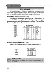
ATX 20-Pin Power Connector: ATX This connector allows you to connect to the CPU. 2 1 4 3 JPW1 JPW1 Pin Definition PIN SIGNAL 1 GND 2 GND 3 12V 4 12V MSI Reminds You... Before inserting the power supply connector, always make sure the plug of 300 (and up) watt is used to provide power to an ... -12V GND PS_ON GND GND GND -5V 5V 5V ATX 12V Power Connector: JPW1 This 12V power connector is highly recommended for the power system. MS-6702 ATX Mainboard Power Supply The mainboard supports ATX power supply for system stability. 2-12
ATX 20-Pin Power Connector: ATX This connector allows you to connect to the CPU. 2 1 4 3 JPW1 JPW1 Pin Definition PIN SIGNAL 1 GND 2 GND 3 12V 4 12V MSI Reminds You... Before inserting the power supply connector, always make sure the plug of 300 (and up) watt is used to provide power to an ... -12V GND PS_ON GND GND GND -5V 5V 5V ATX 12V Power Connector: JPW1 This 12V power connector is highly recommended for the power system. MS-6702 ATX Mainboard Power Supply The mainboard supports ATX power supply for system stability. 2-12
User Guide
Page 35
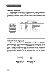
... consumer electronics audio/video (A/V) appliances, storage peripherals, other USB-compatible devices. The mini IEEE1394 port is designed for you to IEEE1394 devices without external power. MS-6702 ATX Mainboard USB 2.0 Connectors The mainboard provides a UHCI (Universal Host Controller Interface) Universal Serial Bus root for attaching USB devices such as keyboard, mouse or...
... consumer electronics audio/video (A/V) appliances, storage peripherals, other USB-compatible devices. The mini IEEE1394 port is designed for you to IEEE1394 devices without external power. MS-6702 ATX Mainboard USB 2.0 Connectors The mainboard provides a UHCI (Universal Host Controller Interface) Universal Serial Bus root for attaching USB devices such as keyboard, mouse or...
User Guide
Page 37
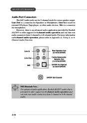
...Rear Speaker Out (in 6CH+S/PDIF) Center/Subwoofer Speaker Out ( in 6CH+S/PDIF) S/PDIF Out-Optical (in 6CH+S/PDIF) S/PDIF Out-Coaxial MSI Reminds You... Line In is used for 6-channel audio operation and can turn rear audio connectors from 2-channel to Appendix A: Using 4- For more... audio chip is an advanced audio application provided by Realtek ALC655 to offer support for microphones. Mic is a connector for Speakers or Headphones. MS-6702 ATX Mainboard Audio Port Connectors The left 3 audio jacks are for 2-channel mode for stereo speaker output: Line Out is a connector for ...
...Rear Speaker Out (in 6CH+S/PDIF) Center/Subwoofer Speaker Out ( in 6CH+S/PDIF) S/PDIF Out-Optical (in 6CH+S/PDIF) S/PDIF Out-Coaxial MSI Reminds You... Line In is used for 6-channel audio operation and can turn rear audio connectors from 2-channel to Appendix A: Using 4- For more... audio chip is an advanced audio application provided by Realtek ALC655 to offer support for microphones. Mic is a connector for Speakers or Headphones. MS-6702 ATX Mainboard Audio Port Connectors The left 3 audio jacks are for 2-channel mode for stereo speaker output: Line Out is a connector for ...
User Guide
Page 39
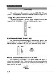
... short. Floppy Disk Drive Connector: FDD1 The mainboard provides a standard floppy disk drive connector that supports 360K, 720K, 1.2M, 1.44M and 2.88M floppy disk types. MS-6702 ATX Mainboard Connectors The mainboard provides connectors to connect to a 2-pin chassis switch.
... short. Floppy Disk Drive Connector: FDD1 The mainboard provides a standard floppy disk drive connector that supports 360K, 720K, 1.2M, 1.44M and 2.88M floppy disk types. MS-6702 ATX Mainboard Connectors The mainboard provides connectors to connect to a 2-pin chassis switch.
User Guide
Page 41
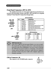
... cable to the front panel switches and LEDs. JFP2 Pin Definition PIN SIGNAL 1 GND 3 SLED 5 PLED 7 NC PIN SIGNAL 2 SPK- 4 BUZ+ 6 BUZ- 8 SPK+ MSI Reminds You... CD-In Connector: J4 The connector is for electrical connection to the computer again in at least five senconds. If the Power LED... on the front panel flashes every two seconds, this signal tells you that the CUP has been protected due to GND Reserved. MS-6702 ATX Mainboard Front Panel Connectors: JFP1 & JFP2 The mainboard provides two front panel connectors for CD-ROM audio connector.
... cable to the front panel switches and LEDs. JFP2 Pin Definition PIN SIGNAL 1 GND 3 SLED 5 PLED 7 NC PIN SIGNAL 2 SPK- 4 BUZ+ 6 BUZ- 8 SPK+ MSI Reminds You... CD-In Connector: J4 The connector is for electrical connection to the computer again in at least five senconds. If the Power LED... on the front panel flashes every two seconds, this signal tells you that the CUP has been protected due to GND Reserved. MS-6702 ATX Mainboard Front Panel Connectors: JFP1 & JFP2 The mainboard provides two front panel connectors for CD-ROM audio connector.
User Guide
Page 43
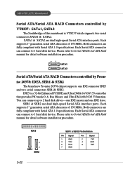
... controller that provides PIO mode 0~6, Bus Master, and Ultra DMA 66/100/133 function. Each supports 1st generation serial ATA data rates of 150 MB/s. MS-6702 ATX Mainboard Serial ATA/Serial ATA RAID Connectors controlled by Promise 20378: IDE3, SER1 & SER2 The brand new Promise 20378 chipset supports one IDE slave...
... controller that provides PIO mode 0~6, Bus Master, and Ultra DMA 66/100/133 function. Each supports 1st generation serial ATA data rates of 150 MB/s. MS-6702 ATX Mainboard Serial ATA/Serial ATA RAID Connectors controlled by Promise 20378: IDE3, SER1 & SER2 The brand new Promise 20378 chipset supports one IDE slave...
User Guide
Page 45
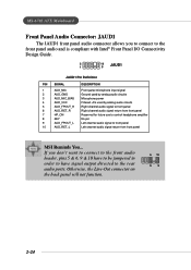
... from front panel 7 HP_ON Reserved for future use to control headphone amplifier 8 KEY No pin 9 AUD_FPOUT_L Left channel audio signal to the rear audio ports. MS-6702 ATX Mainboard Front Panel Audio Connector: JAUD1 The JAUD1 front panel audio connector allows you don't want to connect to the front audio header, pins... 5 & 6, 9 & 10 have to be jumpered in order to have signal output directed to front panel 10 AUD_RET_L Left channel audio signal return from front panel MSI Reminds You...
... from front panel 7 HP_ON Reserved for future use to control headphone amplifier 8 KEY No pin 9 AUD_FPOUT_L Left channel audio signal to the rear audio ports. MS-6702 ATX Mainboard Front Panel Audio Connector: JAUD1 The JAUD1 front panel audio connector allows you don't want to connect to the front audio header, pins... 5 & 6, 9 & 10 have to be jumpered in order to have signal output directed to front panel 10 AUD_RET_L Left channel audio signal return from front panel MSI Reminds You...


