User Guide
Page 3
... MICRO-STAR INTERNATIONAL. AMI® is the intellectual property of AMD Corporation. AMD, Athlon™, Athlon™ XP, Thoroughbred™, and Duron™ are registered trademarks of Novell, Inc. Netware® is a registered trademark of Intel Corporation. Alternatively, please try the following help resources for FAQ, technical guide, BIOS updates, driver updates, and other information: http://www.msi.com...
... MICRO-STAR INTERNATIONAL. AMI® is the intellectual property of AMD Corporation. AMD, Athlon™, Athlon™ XP, Thoroughbred™, and Duron™ are registered trademarks of Novell, Inc. Netware® is a registered trademark of Intel Corporation. Alternatively, please try the following help resources for FAQ, technical guide, BIOS updates, driver updates, and other information: http://www.msi.com...
User Guide
Page 5
... Layout 1-4 MSI Special Features 1-5 Color Management 1-5 Core Center 1-6 Core Cell™ Chip 1-9 Dynamic Overclocking Technology 1-10 Live BIOS™/Live Driver 1-11 Live Monitor 1-12 D-Bracket™ 2 (Optional 1-13 Chapter 2. Hardware Setup 2-1 Quick Components Guide 2-2 Central Processing Unit: CPU 2-3 CPU Installation Procedures for Socket 754 2-4 Installing AMD Athlon64 CPU Cooler Set 2-5 Memory 2-9 Introduction to DDR SDRAM 2-9 DDR DIMM Module Combination 2-10 Installing DDR Modules 2-10 Recommended Memory Combination List 2-11 Power Supply 2-12 ATX 20-Pin...
... Layout 1-4 MSI Special Features 1-5 Color Management 1-5 Core Center 1-6 Core Cell™ Chip 1-9 Dynamic Overclocking Technology 1-10 Live BIOS™/Live Driver 1-11 Live Monitor 1-12 D-Bracket™ 2 (Optional 1-13 Chapter 2. Hardware Setup 2-1 Quick Components Guide 2-2 Central Processing Unit: CPU 2-3 CPU Installation Procedures for Socket 754 2-4 Installing AMD Athlon64 CPU Cooler Set 2-5 Memory 2-9 Introduction to DDR SDRAM 2-9 DDR DIMM Module Combination 2-10 Installing DDR Modules 2-10 Recommended Memory Combination List 2-11 Power Supply 2-12 ATX 20-Pin...

User Guide
Page 8
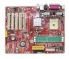
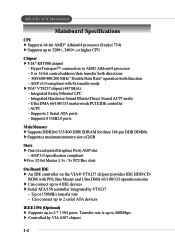
Getting Started Getting Started Thank you for digital audio transmission. The K8T Neo is based on VIA® K8T800 North Bridge & VT8237 South Bridge chipsets and provides eight USB 2.0 ports for high-speed data transmission, RealTek ALC655 chip for 6-channel audio output, and a SPDIF interface for purchasing K8T Neo (MS-6702 v1.X) ATX mainboard. Getting Started Chapter 1. Designed to fit the advanced AMD® Athlon64 processors, the K8T Neo delivers a high performance and professional desktop platform solution. 1-1
Getting Started Getting Started Thank you for digital audio transmission. The K8T Neo is based on VIA® K8T800 North Bridge & VT8237 South Bridge chipsets and provides eight USB 2.0 ports for high-speed data transmission, RealTek ALC655 chip for 6-channel audio output, and a SPDIF interface for purchasing K8T Neo (MS-6702 v1.X) ATX mainboard. Getting Started Chapter 1. Designed to fit the advanced AMD® Athlon64 processors, the K8T Neo delivers a high performance and professional desktop platform solution. 1-1
User Guide
Page 9
... Graphics Port) AGP slot. - AGP v3.0 compliant with PIO, Bus Master and Ultra DMA 66/100/133 operation modes h Can connect up to 400Mbps h Controlled by VT8237 - AGP 3.0 specification compliant hFive 32-bit Master 3.3v / 5v PCI Bus slots On-Board IDE h An IDE controller on the VIA® VT8237 chipset provides IDE HDD/CD- ACPI - Integrated Hardware Sound Blaster/Direct Sound AC97 audio - Can connect up to 2 serial ATA devices IEEE 1394 (Optional) h Supports up to AMD Athlon64 processor...
... Graphics Port) AGP slot. - AGP v3.0 compliant with PIO, Bus Master and Ultra DMA 66/100/133 operation modes h Can connect up to 400Mbps h Controlled by VT8237 - AGP 3.0 specification compliant hFive 32-bit Master 3.3v / 5v PCI Bus slots On-Board IDE h An IDE controller on the VIA® VT8237 chipset provides IDE HDD/CD- ACPI - Integrated Hardware Sound Blaster/Direct Sound AC97 audio - Can connect up to 2 serial ATA devices IEEE 1394 (Optional) h Supports up to AMD Athlon64 processor...
User Guide
Page 10
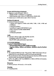
... On-Board (Optional) h Supports 2 serial ATA plus 1 ATA133 - Compliance with 360K, 720K, 1.2M, 1.44M and 2.88Mbytes - 1 serial port (COMA) - 1 parallel port supports SPP/EPP/ECP mode - 1 IrDA connector for SIR/ASKIR/HPSIR - 1 audio port - 1 D-Bracket2 pinheader Audio h 6 channels software audio codec RealTek ALC655. - RAID 0, RAID 1 or RAID 0+1 is supported - h The mainboard provides a Desktop Management Interface (DMI) function which detects the pe- RAID function work w/ATA133+SATA H/D or 2SATA H/D h Connect up to 2 SATA device and 2 ATA133 devices On-Board Peripherals h On-Board...
... On-Board (Optional) h Supports 2 serial ATA plus 1 ATA133 - Compliance with 360K, 720K, 1.2M, 1.44M and 2.88Mbytes - 1 serial port (COMA) - 1 parallel port supports SPP/EPP/ECP mode - 1 IrDA connector for SIR/ASKIR/HPSIR - 1 audio port - 1 D-Bracket2 pinheader Audio h 6 channels software audio codec RealTek ALC655. - RAID 0, RAID 1 or RAID 0+1 is supported - h The mainboard provides a Desktop Management Interface (DMI) function which detects the pe- RAID function work w/ATA133+SATA H/D or 2SATA H/D h Connect up to 2 SATA device and 2 ATA133 devices On-Board Peripherals h On-Board...
User Guide
Page 18
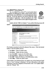
... the desired button to search for the correct BIOS/driver version throughout the whole Web site. Getting Started Live BIOS™/Live Driver™ The Live BIOS™/Live Driver™ is displayed. If the product you purchased does not support any of the screen. Updates the BIOS online. Ø Live Driver - Updates the firmware of the OSD products online. Ø Live Utility - After the installation, the "MSI Live Update 3" icon...
... the desired button to search for the correct BIOS/driver version throughout the whole Web site. Getting Started Live BIOS™/Live Driver™ The Live BIOS™/Live Driver™ is displayed. If the product you purchased does not support any of the screen. Updates the BIOS online. Ø Live Driver - Updates the firmware of the OSD products online. Ø Live Utility - After the installation, the "MSI Live Update 3" icon...
User Guide
Page 24
.... Overclocking This motherboard is designed to operate beyond product specifications. 2-3 The mainboard uses a CPU socket called Socket-754 for easy CPU installation. MSI Reminds You... We do not have the heat sink and cooling fan, contact your components are installing the CPU, make sure the CPU has a heat sink and a cooling fan attached on the computer. Replacing the CPU While replacing the CPU, always turn off the ATX power supply or unplug the power supply's power cord...
.... Overclocking This motherboard is designed to operate beyond product specifications. 2-3 The mainboard uses a CPU socket called Socket-754 for easy CPU installation. MSI Reminds You... We do not have the heat sink and cooling fan, contact your components are installing the CPU, make sure the CPU has a heat sink and a cooling fan attached on the computer. Replacing the CPU While replacing the CPU, always turn off the ATX power supply or unplug the power supply's power cord...
User Guide
Page 39
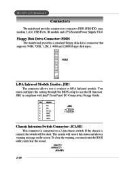
..., IDE HDD, case, modem, LAN, USB Ports, IR module and CPU/System/Power Supply FAN. You must enter the BIOS utility and clear the record. Pin Signal 1 NC 2 NC 3 VCC5 4 GND 5 IRTX 6 IRRX JIR1 2 6 1 5 Chassis Intrusion Switch Connector: JCASE1 This connector is compliant with Intel® Front Panel I/O Connectivity Design Guide. The system will be short. FDD1 IrDA Infrared Module Header: JIR1 The connector allows you must configure the setting through the BIOS setup to a 2-pin chassis switch. GND 2 CINTRU 1 JCASE1 2-18 Floppy Disk Drive Connector...
..., IDE HDD, case, modem, LAN, USB Ports, IR module and CPU/System/Power Supply FAN. You must enter the BIOS utility and clear the record. Pin Signal 1 NC 2 NC 3 VCC5 4 GND 5 IRTX 6 IRRX JIR1 2 6 1 5 Chassis Intrusion Switch Connector: JCASE1 This connector is compliant with Intel® Front Panel I/O Connectivity Design Guide. The system will be short. FDD1 IrDA Infrared Module Header: JIR1 The connector allows you must configure the setting through the BIOS setup to a 2-pin chassis switch. GND 2 CINTRU 1 JCASE1 2-18 Floppy Disk Drive Connector...
User Guide
Page 40
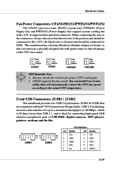
... +12V SENSOR PWFAN2 MSI Reminds You... 1. USB 2.0 technology increases data transfer rate up to the +12V, the black wire is ideal for proper CPU cooling fan. 2. You can install Core Center utility that the red wire is the positive and should be connected to a maximum throughput of the CPU fan control. This mainboard has a System Hardware Monitor chipset on-board, so that are compliant with speed sensor to take...
... +12V SENSOR PWFAN2 MSI Reminds You... 1. USB 2.0 technology increases data transfer rate up to the +12V, the black wire is ideal for proper CPU cooling fan. 2. You can install Core Center utility that the red wire is the positive and should be connected to a maximum throughput of the CPU fan control. This mainboard has a System Hardware Monitor chipset on-board, so that are compliant with speed sensor to take...
User Guide
Page 47
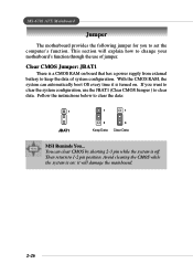
... ATX Mainboard Jumper The motherboard provides the following jumper for you want to clear the data: 1 JBAT1 1 1 3 Keep Data 3 Clear Data MSI Reminds You... Clear CMOS Jumper: JBAT1 There is turned on ; You can automatically boot OS every time it will explain how to change your motherboard's function through the use the JBAT1 (Clear CMOS Jumper ) to keep the data of jumper. it is a CMOS RAM on board that has a power supply from external battery to clear...
... ATX Mainboard Jumper The motherboard provides the following jumper for you want to clear the data: 1 JBAT1 1 1 3 Keep Data 3 Clear Data MSI Reminds You... Clear CMOS Jumper: JBAT1 There is turned on ; You can automatically boot OS every time it will explain how to change your motherboard's function through the use the JBAT1 (Clear CMOS Jumper ) to keep the data of jumper. it is a CMOS RAM on board that has a power supply from external battery to clear...
User Guide
Page 48
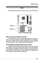
... Setup Slots The motherboard provides one AGP slot, and five 32-bit PCI bus slots. When adding or removing expansion cards, make any necessary hardware or software settings for the graphics controller to directly access main memory. AGP Slot PCI Slots AGP (Accelerated Graphics Port) Slot The AGP slot allows you to meet your needs. PCI (Peripheral Component Interconnect) Slots The PCI slots allow you unplug the power supply first. It introduces a 66MHz, 32-bit channel for the expansion card, such as jumpers, switches or BIOS configuration...
... Setup Slots The motherboard provides one AGP slot, and five 32-bit PCI bus slots. When adding or removing expansion cards, make any necessary hardware or software settings for the graphics controller to directly access main memory. AGP Slot PCI Slots AGP (Accelerated Graphics Port) Slot The AGP slot allows you to meet your needs. PCI (Peripheral Component Interconnect) Slots The PCI slots allow you unplug the power supply first. It introduces a 66MHz, 32-bit channel for the expansion card, such as jumpers, switches or BIOS configuration...
User Guide
Page 51
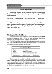
... still use the original first boot device to trigger the boot menu. DEL:Setup F11:Boot Menu F12:Network boot TAB:Logo If the message disappears before you respond and you power on the screen, press to boot up. 3-2 Select First Boot Device Floppy IDE-0 CDROM : 1st Floppy : IBM-DTLA-307038 : ATAPI CD-ROM DRIVE 40X M [Up/Dn] Select [RETURN] Boot [ESC] cancel The boot menu will start POST (Power On Self Test) process. MS-6702 ATX Mainboard Entering Setup Power...
... still use the original first boot device to trigger the boot menu. DEL:Setup F11:Boot Menu F12:Network boot TAB:Logo If the message disappears before you respond and you power on the screen, press to boot up. 3-2 Select First Boot Device Floppy IDE-0 CDROM : 1st Floppy : IBM-DTLA-307038 : ATAPI CD-ROM DRIVE 40X M [Up/Dn] Select [RETURN] Boot [ESC] cancel The boot menu will start POST (Power On Self Test) process. MS-6702 ATX Mainboard Entering Setup Power...
User Guide
Page 58
... opportunity to search for the hard disks. BIOS Setup porting Technology) capability for floppy disk drives at boot time. Option Setup Always Description The password prompt appears only when end users try to a safe place before the hard disk becomes offline. Settings: Enabled, Disabled. Setting to Off will turn on the Num Lock key when the system is a utility that is possible if you to use the arrow keys on . Primary Display This configures the primary subsystem in...
... opportunity to search for the hard disks. BIOS Setup porting Technology) capability for floppy disk drives at boot time. Option Setup Always Description The password prompt appears only when end users try to a safe place before the hard disk becomes offline. Settings: Enabled, Disabled. Setting to Off will turn on the Num Lock key when the system is a utility that is possible if you to use the arrow keys on . Primary Display This configures the primary subsystem in...
User Guide
Page 62
... technology allows the CPU to write directly to the AGP without passing anything through the system memory and improves the AGP 4X speed. Select Enabled only when the installed AGP card supports this function. Host cycles that hit the aperture range are forwarded to the graphics card without any translation. Select 4x only if your AGP card supports it. AGP Aperture Size This setting controls...
... technology allows the CPU to write directly to the AGP without passing anything through the system memory and improves the AGP 4X speed. Select Enabled only when the installed AGP card supports this function. Host cycles that hit the aperture range are forwarded to the graphics card without any translation. Select 4x only if your AGP card supports it. AGP Aperture Size This setting controls...

User Guide
Page 68
... each PCI device can conduct transactions for a longer time and thus improve the effective PCI bandwidth. Primary Graphics Adaptor This setting specifies which VGA card is your primary graphics adapter. Setting options: PCI, AGP. When set the item to higher values, every PCI device can hold the bus before another takes over. Settings options: Disabled, Enabled. BIOS Setup PCI Latency Timer This item controls how long each PCI slot. 3-19 For better PCI performance, you should set to...
... each PCI device can conduct transactions for a longer time and thus improve the effective PCI bandwidth. Primary Graphics Adaptor This setting specifies which VGA card is your primary graphics adapter. Setting options: PCI, AGP. When set the item to higher values, every PCI device can hold the bus before another takes over. Settings options: Disabled, Enabled. BIOS Setup PCI Latency Timer This item controls how long each PCI slot. 3-19 For better PCI performance, you should set to...
User Guide
Page 70
... item sets the operation mode for IR function). IR Pin Select Set to IRRX/IRTX when using an internal IR module connected to enable the onboard Floppy controller or not. Settings: Auto, 378, 278, Disabled. Settings: Auto, 3F8/COM1, 2F8/COM2, 3E8/ COM3, 2E8/COM4 and Disabled. Serial Port 1 These items specify the base I /O port address. Selecting Auto allows AMIBIOS to automatically determine the correct base I /O port addresses of the onboard parallel port. Option Auto Enabled Disabled Description BIOS...
... item sets the operation mode for IR function). IR Pin Select Set to IRRX/IRTX when using an internal IR module connected to enable the onboard Floppy controller or not. Settings: Auto, 378, 278, Disabled. Settings: Auto, 3F8/COM1, 2F8/COM2, 3E8/ COM3, 2E8/COM4 and Disabled. Serial Port 1 These items specify the base I /O port address. Selecting Auto allows AMIBIOS to automatically determine the correct base I /O port addresses of the onboard parallel port. Option Auto Enabled Disabled Description BIOS...
User Guide
Page 72
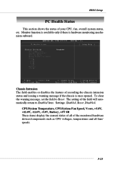
..., Battery, +5V SB These items display the current status of all of your CPU, fan, overall system status, etc. The setting of recording the chassis intrusion status and issuing a warning message if the chassis is hardware monitoring mechanism onboard. BIOS Setup PC Health Status This section shows the status of the monitored hardware devices/components such as CPU voltages, temperatures and all fans' speeds. 3-23 Settings: Enabled, Reset, Disabled. Chassis Intrusion The field enables...
..., Battery, +5V SB These items display the current status of all of your CPU, fan, overall system status, etc. The setting of recording the chassis intrusion status and issuing a warning message if the chassis is hardware monitoring mechanism onboard. BIOS Setup PC Health Status This section shows the status of the monitored hardware devices/components such as CPU voltages, temperatures and all fans' speeds. 3-23 Settings: Enabled, Reset, Disabled. Chassis Intrusion The field enables...
User Guide
Page 79
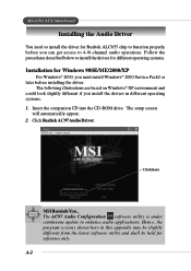
... into the CD-ROM drive. The AC97 Audio Configuration software utility is under continuous update to function properly before you must install Windows® 2000 Service Pack2 or later before installing the driver. Click here MSI Reminds You... The setup screen will automatically appear. 2. Click Realtek AC97 Audio Driver. Hence, the program screens shown here in different operating systems. 1. A-2 MS-6702 ATX Mainboard Installing the Audio Driver You need to install the driver for reference...
... into the CD-ROM drive. The AC97 Audio Configuration software utility is under continuous update to function properly before you must install Windows® 2000 Service Pack2 or later before installing the driver. Click here MSI Reminds You... The setup screen will automatically appear. 2. Click Realtek AC97 Audio Driver. Hence, the program screens shown here in different operating systems. 1. A-2 MS-6702 ATX Mainboard Installing the Audio Driver You need to install the driver for reference...
User Guide
Page 94
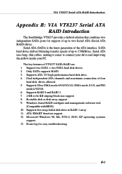
... SATA ports for easy troubleshooting. Dual independent ATA channels and maximum connection of VT8237 SATA RAID are: 1. Microsoft Windows 98, Me, NT4.0, 2000, XP operating systems support. 13. Support two SATA + two PATA hard disk drives. 2. VIA VT8237 Serial ATA RAID Introduction Appendix. The key features of four hard disk drives allowed. 5. Bootable disk or disk array support. 9. Serial ATA (SATA) is the latest generation of up to 64 KB striping block size support. 8. Supports ATA 133 high performance hard disk drive. 4. Serial ATA uses long...
... SATA ports for easy troubleshooting. Dual independent ATA channels and maximum connection of VT8237 SATA RAID are: 1. Microsoft Windows 98, Me, NT4.0, 2000, XP operating systems support. 13. Support two SATA + two PATA hard disk drives. 2. VIA VT8237 Serial ATA RAID Introduction Appendix. The key features of four hard disk drives allowed. 5. Bootable disk or disk array support. 9. Serial ATA (SATA) is the latest generation of up to 64 KB striping block size support. 8. Supports ATA 133 high performance hard disk drive. 4. Serial ATA uses long...
User Guide
Page 107
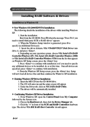
.../NT4) Installation The following details the installation of the SCSI and RAID Controllers hardware type. The CD will auto-run and the setup screen will now load all devices are specified, press to specify an Additional Device(s). 3. From Windows XP, open the Control Panel from the CD-ROM. Press to continue with installation. 6. The driver VIA IDE RAID Host Controller should appear. MS-6702 ATX Mainboard Installing RAID Software & Drivers Install Driver in front of the drivers while installing Windows XP...
.../NT4) Installation The following details the installation of the SCSI and RAID Controllers hardware type. The CD will auto-run and the setup screen will now load all devices are specified, press to specify an Additional Device(s). 3. From Windows XP, open the Control Panel from the CD-ROM. Press to continue with installation. 6. The driver VIA IDE RAID Host Controller should appear. MS-6702 ATX Mainboard Installing RAID Software & Drivers Install Driver in front of the drivers while installing Windows XP...

