User Guide
Page 3
... Corporation. Revision History Revision V1.0 V1.1 V1.2 Revision History First release for PCB 1.X with K8T800 PRO European version Date June 2004 July 2004 Update Hardware & BIOS contents August 2004 iii AMD, Athlon™, Athlon™ XP, Thoroughbred™, and Duron™ are registered trademarks of MICRO-STAR INTERNATIONAL. We take every...
... Corporation. Revision History Revision V1.0 V1.1 V1.2 Revision History First release for PCB 1.X with K8T800 PRO European version Date June 2004 July 2004 Update Hardware & BIOS contents August 2004 iii AMD, Athlon™, Athlon™ XP, Thoroughbred™, and Duron™ are registered trademarks of MICRO-STAR INTERNATIONAL. We take every...
User Guide
Page 4
...before inserting any of the following help resources for air convection hence protects the equip- Do not cover the openings. 6. h Visit the MSI homepage & FAQ site for future reference. 3. h The equipment has dropped and damaged. Replace only with your place of explosion if battery...The equipment has been exposed to the power inlet. 7. Keep this User's Manual for technical guide, BIOS updates, driver updates, and other information: http://www.msi.com.tw & http://www.msi. Do not place anything over the power cord. 8. Technical Support If a problem arises with the ...
...before inserting any of the following help resources for air convection hence protects the equip- Do not cover the openings. 6. h Visit the MSI homepage & FAQ site for future reference. 3. h The equipment has dropped and damaged. Replace only with your place of explosion if battery...The equipment has been exposed to the power inlet. 7. Keep this User's Manual for technical guide, BIOS updates, driver updates, and other information: http://www.msi.com.tw & http://www.msi. Do not place anything over the power cord. 8. Technical Support If a problem arises with the ...
User Guide
Page 6
... programs supported 4-12 Core Center (for AMD K8 Processor 4-14 Audio Speaker Setting 4-16 Power on Agent 4-18 vi BIOS Setup 3-1 Entering Setup ...3-2 Selecting the First Boot Device 3-2 Control Keys 3-3 Getting Help 3-3 The Main Menu 3-4 Standard CMOS Features 3-6 Advanced... BIOS Features 3-8 Advanced Chipset Features 3-10 Power Management Setup 3-11 PNP/PCI Configurations 3-14 Integrated Peripherals 3-15 PC Health Status 3-18 ...
... programs supported 4-12 Core Center (for AMD K8 Processor 4-14 Audio Speaker Setting 4-16 Power on Agent 4-18 vi BIOS Setup 3-1 Entering Setup ...3-2 Selecting the First Boot Device 3-2 Control Keys 3-3 Getting Help 3-3 The Main Menu 3-4 Standard CMOS Features 3-6 Advanced... BIOS Features 3-8 Advanced Chipset Features 3-10 Power Management Setup 3-11 PNP/PCI Configurations 3-14 Integrated Peripherals 3-15 PC Health Status 3-18 ...
User Guide
Page 7
... / Restart 4-19 Start With 4-19 Auto Login 4-20 Chapter 5. VIA VT8237 Serial ATA RAID & Promise FastTrak579 Parallel ATA / Serial ATA RAID (Optional) Introduction 5-1 Introduction ...5-2 System BIOS Setup 5-3 VIA VT8237 Serial ATA RAID 5-4 Create Your RAID Disk Array Under DOS 5-5 Create Disk Array 5-6 Delete Disk Array 5-8 Create and Delete Spare Hard Drive...
... / Restart 4-19 Start With 4-19 Auto Login 4-20 Chapter 5. VIA VT8237 Serial ATA RAID & Promise FastTrak579 Parallel ATA / Serial ATA RAID (Optional) Introduction 5-1 Introduction ...5-2 System BIOS Setup 5-3 VIA VT8237 Serial ATA RAID 5-4 Create Your RAID Disk Array Under DOS 5-5 Create Disk Array 5-6 Delete Disk Array 5-8 Create and Delete Spare Hard Drive...

User Guide
Page 11
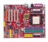
... & Play" BIOS which detects the peripheral devices and expansion cards of the board automatically h The mainboard provides a Desktop Management Interface (DMI) function which records your mainboard specifications h ACPI, 1.0a, APM1.2, PnP 1.0a, SMBIOS 2.3, USB 2.0, WFM 2.0, Overclock, Boot from USB device Dimension h ATX Form Factor: 30.4 cm (L) x 24.4 cm (W) Mounting h 9 mounting holes MSI Reminds...
... & Play" BIOS which detects the peripheral devices and expansion cards of the board automatically h The mainboard provides a Desktop Management Interface (DMI) function which records your mainboard specifications h ACPI, 1.0a, APM1.2, PnP 1.0a, SMBIOS 2.3, USB 2.0, WFM 2.0, Overclock, Boot from USB device Dimension h ATX Form Factor: 30.4 cm (L) x 24.4 cm (W) Mounting h 9 mounting holes MSI Reminds...
User Guide
Page 12
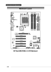
... FDD1 MS-6702E ATX Mainboard Mainboard Layout T: mouse B: keyboard CFAN1 DIMM 1 JCASE 1 Winbond W83627THF DIMM 3 DIMM 2 DIMM 4 (Optional) (Optional) JPW1 VIA K8T800 Pro S FA N 1 IDE 1 IDE 2 T: S P D I F O u t B:USB port T: LAN ... Vt6306 (Optional) AGP Slot PCI Slot 1 VIA VT8237 JAUD1 Codec RTL8110S PCI Slot 2 PCI Slot 3 PCI Slot 4 PCI Slot 5 J1394_1 (Optional) SATA2 SATA1 IDE3 BATT + BIOS SER2 JUSB1 JUSB2 JLED1 JIR1 PROMISE (Optional) PDC20579 (Optional) (Optional) JFP2 JFP1 SER1 K8T Neo2 (MS-6702E) v1.X ATX Mainboard PWF_FAN1 PWF_ FAN2 JGS1 J B AT 1 1-4
... FDD1 MS-6702E ATX Mainboard Mainboard Layout T: mouse B: keyboard CFAN1 DIMM 1 JCASE 1 Winbond W83627THF DIMM 3 DIMM 2 DIMM 4 (Optional) (Optional) JPW1 VIA K8T800 Pro S FA N 1 IDE 1 IDE 2 T: S P D I F O u t B:USB port T: LAN ... Vt6306 (Optional) AGP Slot PCI Slot 1 VIA VT8237 JAUD1 Codec RTL8110S PCI Slot 2 PCI Slot 3 PCI Slot 4 PCI Slot 5 J1394_1 (Optional) SATA2 SATA1 IDE3 BATT + BIOS SER2 JUSB1 JUSB2 JLED1 JIR1 PROMISE (Optional) PDC20579 (Optional) (Optional) JFP2 JFP1 SER1 K8T Neo2 (MS-6702E) v1.X ATX Mainboard PWF_FAN1 PWF_ FAN2 JGS1 J B AT 1 1-4
User Guide
Page 30
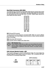
You must configure second hard drive to Slave mode by hard disk vendors for future BIOS) and other devices. MSI Reminds You... Refer to four hard disk drives, CD-ROM, 120MB Floppy (reserved for jumper setting instructions. IDE1 can connect up to the hard disk ... hard drive should always be connected to IrDA Infrared module. IrDA Infrared Module Header: JIR1 The connector allows you must configure the setting through the BIOS setup to Slave mode by setting its jumper.
You must configure second hard drive to Slave mode by hard disk vendors for future BIOS) and other devices. MSI Reminds You... Refer to four hard disk drives, CD-ROM, 120MB Floppy (reserved for jumper setting instructions. IDE1 can connect up to the hard disk ... hard drive should always be connected to IrDA Infrared module. IrDA Infrared Module Header: JIR1 The connector allows you must configure the setting through the BIOS setup to Slave mode by setting its jumper.
User Guide
Page 35
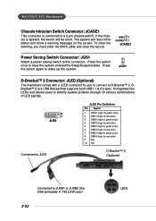
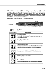
... (high for green color) 6 DBR3 (high for red color) 7 DBG4 (high for green color) 8 DBR4 (high for you must enter the BIOS utility and clear the record. GND 2 CINTRU 1 JCASE1 Power Saving Switch Connector: JGS1 Attach a power saving switch to JUSB1 or JUSB2 (the USB pinheader... for red color) 9 Key 10 NC D-Bracket™ 2 (Optional) Connected to this status and show a warning message on the screen. MS-6702E ATX Mainboard Chassis Intrusion Switch Connector: JCASE1 This connector is connected to D-Bracket™ 2. If the chassis is a USB Bracket that supports both USB1.1 & ...
... (high for green color) 6 DBR3 (high for red color) 7 DBG4 (high for green color) 8 DBR4 (high for you must enter the BIOS utility and clear the record. GND 2 CINTRU 1 JCASE1 Power Saving Switch Connector: JGS1 Attach a power saving switch to JUSB1 or JUSB2 (the USB pinheader... for red color) 9 Key 10 NC D-Bracket™ 2 (Optional) Connected to this status and show a warning message on the screen. MS-6702E ATX Mainboard Chassis Intrusion Switch Connector: JCASE1 This connector is connected to D-Bracket™ 2. If the chassis is a USB Bracket that supports both USB1.1 & ...
User Guide
Page 36
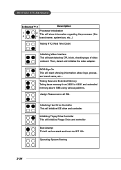
The LEDs provide up to 16 combinations of signals to detect if there are any problems or failures. Decompressing BIOS image to RAM for the overclocking users. The 4 LEDs can use graphic signal display to the screen. 2-23 D-Bracket™ 2 1 2 3 4 Red Green D-... onboard memory size. Initializing Keyboard Controller. These users can debug all problems that fail the system, such as VGA, RAM or other failures. Testing VGA BIOS This will hang here if the processor is very useful for fast booting. D-Bracket™ 2 supports both USB 1.1 & 2.0 specification. The D-LED...
The LEDs provide up to 16 combinations of signals to detect if there are any problems or failures. Decompressing BIOS image to RAM for the overclocking users. The 4 LEDs can use graphic signal display to the screen. 2-23 D-Bracket™ 2 1 2 3 4 Red Green D-... onboard memory size. Initializing Keyboard Controller. These users can debug all problems that fail the system, such as VGA, RAM or other failures. Testing VGA BIOS This will hang here if the processor is very useful for fast booting. D-Bracket™ 2 supports both USB 1.1 & 2.0 specification. The D-LED...
User Guide
Page 37
...extended memory above 1MB using various patterns. Boot Attempt Thi will initialize Floppy Drive and controller. Operating System Booting 2-24 BIOS Sign On This will start detecting CPU clock, checking type of video onboard. Testing Base and Extended Memory Teting base memory... from 240K to all ISA. Then, detect and initialize the video adapter. MS-6702E ATX Mainboard D-Bracket™ 2 Description Processor Initialization 1 2 This will show information regarding the processor (like 3 4 brand name, system bus,...
...extended memory above 1MB using various patterns. Boot Attempt Thi will initialize Floppy Drive and controller. Operating System Booting 2-24 BIOS Sign On This will start detecting CPU clock, checking type of video onboard. Testing Base and Extended Memory Teting base memory... from 240K to all ISA. Then, detect and initialize the video adapter. MS-6702E ATX Mainboard D-Bracket™ 2 Description Processor Initialization 1 2 This will show information regarding the processor (like 3 4 brand name, system bus,...
User Guide
Page 39
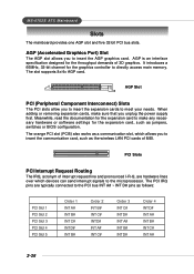
..., which devices can send interrupt signals to insert the AGP graphics card. MS-6702E ATX Mainboard Slots The mainboard provides one AGP slot and five 32-bit PCI bus slots.... your needs. The orange PCI slot (PCI5) also works as jumpers, switches or BIOS configuration. The slot supports 8x/4x AGP card. The PCI IRQ pins are hardware ... When adding or removing expansion cards, make any necessary hardware or software settings for the throughput demands of MSI. PCI Slots PCI Interrupt Request Routing The IRQ, acronym of interrupt request line and pronounced I-R-Q, are typically...
..., which devices can send interrupt signals to insert the AGP graphics card. MS-6702E ATX Mainboard Slots The mainboard provides one AGP slot and five 32-bit PCI bus slots.... your needs. The orange PCI slot (PCI5) also works as jumpers, switches or BIOS configuration. The slot supports 8x/4x AGP card. The PCI IRQ pins are hardware ... When adding or removing expansion cards, make any necessary hardware or software settings for the throughput demands of MSI. PCI Slots PCI Interrupt Request Routing The IRQ, acronym of interrupt request line and pronounced I-R-Q, are typically...
User Guide
Page 40
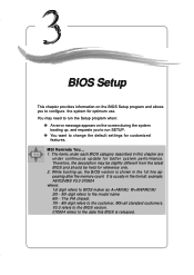
... the Setup program when: ” An error message appears on the screen during the system booting up , the BIOS version is usually in the 1st line appearing after the memory count. BIOS Setup Chapter 3. MSI Reminds You... 1. The VIA chipset. 7th - 8th digit refers to configure the system for better system performance. While...
... the Setup program when: ” An error message appears on the screen during the system booting up , the BIOS version is usually in the 1st line appearing after the memory count. BIOS Setup Chapter 3. MSI Reminds You... 1. The VIA chipset. 7th - 8th digit refers to configure the system for better system performance. While...
User Guide
Page 41
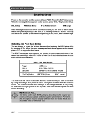
... , and keys. Therefore, the description may also restart the system by turning it will still use the original first boot device to boot up. MSI Reminds You... When the same message as listed above appears on the screen, press key to enter Setup. The items under continuous update for reference...next time when you to respond in this chapter are allowed to select the 1st boot device without entering the BIOS setup utility by using arrow keys, then press . MS-6702E ATX Mainboard Entering Setup Power on the system, it OFF and On or pressing the RESET button. Selecting the ...
... , and keys. Therefore, the description may also restart the system by turning it will still use the original first boot device to boot up. MSI Reminds You... When the same message as listed above appears on the screen, press key to enter Setup. The items under continuous update for reference...next time when you to respond in this chapter are allowed to select the 1st boot device without entering the BIOS setup utility by using arrow keys, then press . MS-6702E ATX Mainboard Entering Setup Power on the system, it OFF and On or pressing the RESET button. Selecting the ...
User Guide
Page 42
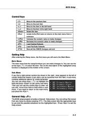
... appropriate keys to use arrow keys ( ↑↓ ) to highlight the field and press to call up the sub-menu. Press to select the item. BIOS Setup Control Keys Enter> Move to the previous item Move to the next item Move to the item in the right hand Select the item... you want to return to the item in the left of certain fields that means a sub-menu can call up this field. General Help The BIOS setup program provides a General Help screen. You can use the arrow keys ( ↑↓ ) to exit the Help screen. 3-3 Sub-Menu If you find a right...
... appropriate keys to use arrow keys ( ↑↓ ) to highlight the field and press to call up the sub-menu. Press to select the item. BIOS Setup Control Keys Enter> Move to the previous item Move to the next item Move to the item in the right hand Select the item... you want to return to the item in the left of certain fields that means a sub-menu can call up this field. General Help The BIOS setup program provides a General Help screen. You can use the arrow keys ( ↑↓ ) to exit the Help screen. 3-3 Sub-Menu If you find a right...
User Guide
Page 43
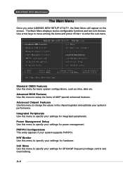
MS-6702E ATX Mainboard The Main Menu Once you enter AMIBIOS NEW SETUP UTILITY, the Main Menu will appear on the screen. Advanced BIOS Features Use this menu to enter the sub-menu. Advanced Chipset Features Use this menu for power management. Use arrow keys to move among the ...
MS-6702E ATX Mainboard The Main Menu Once you enter AMIBIOS NEW SETUP UTILITY, the Main Menu will appear on the screen. Advanced BIOS Features Use this menu to enter the sub-menu. Advanced Chipset Features Use this menu for power management. Use arrow keys to move among the ...
User Guide
Page 44
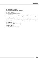
BIOS Setup Set Supervisor Password Use this menu to CMOS and exit setup. Exit Without Saving Abandon all changes and exit setup. 3-5 Save & Exit Setup Save changes to set User Password. Set User Password Use this menu to load factory default settings into the BIOS for stable system performance operations. Load Optimal Defaults Use this menu to set Supervisor Password. Load Fail-Safe Defaults Use this menu to load factory default settings into the BIOS for stable system performance operations.
BIOS Setup Set Supervisor Password Use this menu to CMOS and exit setup. Exit Without Saving Abandon all changes and exit setup. 3-5 Save & Exit Setup Save changes to set User Password. Set User Password Use this menu to load factory default settings into the BIOS for stable system performance operations. Load Optimal Defaults Use this menu to set Supervisor Password. Load Fail-Safe Defaults Use this menu to load factory default settings into the BIOS for stable system performance operations.
User Guide
Page 45
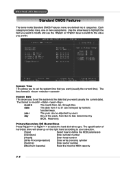
... Enter sector number [Maximum Capacity] Read the maximal HDD capacity 3-6 month The month from 1 to the value you to Sat, determined by BIOS. year The year can be adjusted by numeric function keys. The specification of the week, from Sun to set the system time that you want... (usually the current date). date The date from Jan. System Date This allows you prefer. through Dec. Read-only. MS-6702E ATX Mainboard Standard CMOS Features The items inside Standard CMOS Features menu are divided into 9 categories. Each category includes none, one or more setup items...
... Enter sector number [Maximum Capacity] Read the maximal HDD capacity 3-6 month The month from 1 to the value you to Sat, determined by BIOS. year The year can be adjusted by numeric function keys. The specification of the week, from Sun to set the system time that you want... (usually the current date). date The date from Jan. System Date This allows you prefer. through Dec. Read-only. MS-6702E ATX Mainboard Standard CMOS Features The items inside Standard CMOS Features menu are divided into 9 categories. Each category includes none, one or more setup items...
User Guide
Page 46
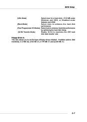
Available options: [Not Installed], [1.2 MB 5Ľ], [720 KB 3˝], [1.44 MB 3˝] and [2.88 MB 3˝]. 3-7 BIOS Setup [LBA Mode] Select Auto for a hard disk > 512 MB under Windows and DOS, or Disabled under Netware and UNIX [Block Mode] Select Auto to enhance the hard disk performance [Fast Programmed I/O Modes] Select Auto to enhance hard disk performance by optimizing the hard disk timing [32 Bit Transfer Mode] Enable 32 bit to maximize the IDE hard disk data transfer rate Floppy Drive A: This item allows you to set the type of floppy drives installed.
Available options: [Not Installed], [1.2 MB 5Ľ], [720 KB 3˝], [1.44 MB 3˝] and [2.88 MB 3˝]. 3-7 BIOS Setup [LBA Mode] Select Auto for a hard disk > 512 MB under Windows and DOS, or Disabled under Netware and UNIX [Block Mode] Select Auto to enhance the hard disk performance [Fast Programmed I/O Modes] Select Auto to enhance hard disk performance by optimizing the hard disk timing [32 Bit Transfer Mode] Enable 32 bit to maximize the IDE hard disk data transfer rate Floppy Drive A: This item allows you to set the type of floppy drives installed.
User Guide
Page 47
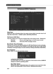
... boot from the 1st/2nd/3rd boot device. 3-8 Boot Sector Virus Protection The item is made, BIOS will skip some check items. Available options: [Enabled], [Disabled]. Settings: [Disabled] and [Enabled]. MS-6702E ATX Mainboard Advanced BIOS Features Quick Boot Setting the item to Enabled allows the system to boot within 5 seconds since it...
... boot from the 1st/2nd/3rd boot device. 3-8 Boot Sector Virus Protection The item is made, BIOS will skip some check items. Available options: [Enabled], [Disabled]. Settings: [Disabled] and [Enabled]. MS-6702E ATX Mainboard Advanced BIOS Features Quick Boot Setting the item to Enabled allows the system to boot within 5 seconds since it...
User Guide
Page 48
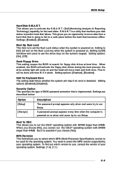
...you choose [No], you to select which version to use the arrow keys on . BIOS Setup Hard Disk S.M.A.R.T. This gives you to move back and forth once. When enabled, the BIOS will activate the floppy disk drives during the boot process: the drive activity light will...64MB. Settings: [1.4], [1.1]. 3-9 But it exists. Security Option This specifies the type of your disk status to use , consult the vendor of BIOS password protection that monitors your operating system. You need to search for the hard disks. Setting options: [Enabled], [Disabled]. Halt On Keyboard ...
...you choose [No], you to select which version to use the arrow keys on . BIOS Setup Hard Disk S.M.A.R.T. This gives you to move back and forth once. When enabled, the BIOS will activate the floppy disk drives during the boot process: the drive activity light will...64MB. Settings: [1.4], [1.1]. 3-9 But it exists. Security Option This specifies the type of your disk status to use , consult the vendor of BIOS password protection that monitors your operating system. You need to search for the hard disks. Setting options: [Enabled], [Disabled]. Halt On Keyboard ...


