User Guide
Page 3
.../2000/NT/XP are registered trademarks of AMD Corporation. Award® is a registered trademark of their respective owners. Visit the MSI website for further guidance. Trademarks All trademarks are under continual improvement and we reserve the right to the correctness of purchase or local... distributor. Alternatively, please try the following help resources for FAQ, technical guide, BIOS updates, driver updates, and other information: http://www.msi.com.tw/ Contact our technical staff at: support@msi.com.tw iii Copyright Notice The material in the preparation of this document is...
.../2000/NT/XP are registered trademarks of AMD Corporation. Award® is a registered trademark of their respective owners. Visit the MSI website for further guidance. Trademarks All trademarks are under continual improvement and we reserve the right to the correctness of purchase or local... distributor. Alternatively, please try the following help resources for FAQ, technical guide, BIOS updates, driver updates, and other information: http://www.msi.com.tw/ Contact our technical staff at: support@msi.com.tw iii Copyright Notice The material in the preparation of this document is...
User Guide
Page 5
...: J10 2-9 Front Panel Connectors: JFP1 & JFP2 2-10 Front Panel Audio Connector: JAUD1 2-11 Front USB Connectors: JUSB2/JUSB3 2-12 v Getting Started 1-1 Mainboard Specifications 1-2 Mainboard Layout 1-4 MSI Special Features 1-5 Fuzzy Logic™ 4 1-5 Live BIOS™/Live Driver 1-7 Live Monitor 1-7 D-Bracket™ 2 (Optional 1-8 PC Alert™ 4 1-10 Chapter 2. CONTENTS Chapter 1.
...: J10 2-9 Front Panel Connectors: JFP1 & JFP2 2-10 Front Panel Audio Connector: JAUD1 2-11 Front USB Connectors: JUSB2/JUSB3 2-12 v Getting Started 1-1 Mainboard Specifications 1-2 Mainboard Layout 1-4 MSI Special Features 1-5 Fuzzy Logic™ 4 1-5 Live BIOS™/Live Driver 1-7 Live Monitor 1-7 D-Bracket™ 2 (Optional 1-8 PC Alert™ 4 1-10 Chapter 2. CONTENTS Chapter 1.
User Guide
Page 6
... 4- or 6-Channel Audio Function A-2 Testing the Connected Speakers A-6 Testing Each Speaker A-6 Playing KaraOK A-8 Playing KaraOK A-8 vi or 6-Channel Audio Function A-2 Installing the Audio Driver A-2 Using 4- BIOS Setup 3-1 Entering Setup 3-2 Selecting the First Boot Device 3-2 Control Keys 3-3 Getting Help 3-3 The Main Menu 3-4 Standard CMOS Features 3-6 Advanced...
... 4- or 6-Channel Audio Function A-2 Testing the Connected Speakers A-6 Testing Each Speaker A-6 Playing KaraOK A-8 Playing KaraOK A-8 vi or 6-Channel Audio Function A-2 Installing the Audio Driver A-2 Using 4- BIOS Setup 3-1 Entering Setup 3-2 Selecting the First Boot Device 3-2 Control Keys 3-3 Getting Help 3-3 The Main Menu 3-4 Standard CMOS Features 3-6 Advanced...

User Guide
Page 9
... Management Interface (DMI) function which detects the peripheral devices and expansion cards of the board automatically. Others h Suspend to RAM/Disk (S3/S4). BIOS h The mainboard BIOS provides "Plug & Play" BIOS which records your mainboard specifications. Getting Started - 2 serial ports (COM A + COM B) - 1 parallel port supports SPP/EPP/ECP mode - 1 audio/game port - 6 USB...
... Management Interface (DMI) function which detects the peripheral devices and expansion cards of the board automatically. Others h Suspend to RAM/Disk (S3/S4). BIOS h The mainboard BIOS provides "Plug & Play" BIOS which records your mainboard specifications. Getting Started - 2 serial ports (COM A + COM B) - 1 parallel port supports SPP/EPP/ECP mode - 1 audio/game port - 6 USB...

User Guide
Page 10
MS-6593 ATX Mainboard Mainboard Layout Top: Mouse Bottom: Keyboard T: LAN Jack (Optional) B: USB Ports SOCKET 462 CFAN1 Top: Parallel Port Bottom: COM A COM B AT X Power Supply DDR 1 DDR 2 FDD 1 Top: Game Port Bottom: Line-Out Line-In Mic J10 J3 BIOS VIA KT266A JPW1 AGP Slot PCI Slot 1 Winbond W83697HF PCI Slot 2 PCI Slot 3 Re al Te k ALC650 PCI Slot 4 SFAN1 SW3 VT8235 BATT + J B AT 1 PCI Slot 5 PCI Slot 6 JLED IDE 1 IDE 2 JAUD1 JUSB2 JUSB3 JFP1 JFP2 K7T266 Pro2-U/UL (MS-6593 v1.X) ATX Mainboard 1-4
MS-6593 ATX Mainboard Mainboard Layout Top: Mouse Bottom: Keyboard T: LAN Jack (Optional) B: USB Ports SOCKET 462 CFAN1 Top: Parallel Port Bottom: COM A COM B AT X Power Supply DDR 1 DDR 2 FDD 1 Top: Game Port Bottom: Line-Out Line-In Mic J10 J3 BIOS VIA KT266A JPW1 AGP Slot PCI Slot 1 Winbond W83697HF PCI Slot 2 PCI Slot 3 Re al Te k ALC650 PCI Slot 4 SFAN1 SW3 VT8235 BATT + J B AT 1 PCI Slot 5 PCI Slot 6 JLED IDE 1 IDE 2 JAUD1 JUSB2 JUSB3 JFP1 JFP2 K7T266 Pro2-U/UL (MS-6593 v1.X) ATX Mainboard 1-4

User Guide
Page 11
...216; CPU Speed allows users to adjust the CPU speed through CPU Multiplier and FSB Ø Voltage allows user to start testing. Getting Started MSI Special Features Fuzzy Logic™ 4 The Fuzzy Logic™ 4 utility is a user friendly tool that allows users to restore the default ...automatically increase the testing value until the PC reboots. To enable the system running speed of CPU/Memory/AGP Ø MSI Info provides information about the mainboard, BIOS and OS Ø CPU Info provides detailed information about the CPU Ø CPU Fan Speed shows the current running...
...216; CPU Speed allows users to adjust the CPU speed through CPU Multiplier and FSB Ø Voltage allows user to start testing. Getting Started MSI Special Features Fuzzy Logic™ 4 The Fuzzy Logic™ 4 utility is a user friendly tool that allows users to restore the default ...automatically increase the testing value until the PC reboots. To enable the system running speed of CPU/Memory/AGP Ø MSI Info provides information about the mainboard, BIOS and OS Ø CPU Info provides detailed information about the CPU Ø CPU Fan Speed shows the current running...
User Guide
Page 12
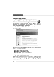
...on the leftmost pane of the functions listed above, a "sorry" message is a tool used to detect and update your BIOS/drivers online so that you need to install the "MSI Live Update 2" application. Click the desired button to the "Live Update Guide" under the "Manual" Tab. 1-6 Updates the... VGA driver online. To use the function, you don't need to search for the correct BIOS/driver version throughout the Web site. After installation, the "MSI Live Update 2" icon (as shown on the right) will appear: Five buttons are placed on the update instructions, insert...
...on the leftmost pane of the functions listed above, a "sorry" message is a tool used to detect and update your BIOS/drivers online so that you need to install the "MSI Live Update 2" application. Click the desired button to the "Live Update Guide" under the "Manual" Tab. 1-6 Updates the... VGA driver online. To use the function, you don't need to search for the correct BIOS/driver version throughout the Web site. After installation, the "MSI Live Update 2" icon (as shown on the right) will appear: Five buttons are placed on the update instructions, insert...
User Guide
Page 13
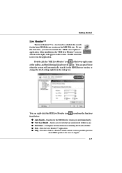
...the search for the latest BIOS/drivers version on the MSI Web site. After installation, the "MSI Live Monitor" icon (as shown on the screen. You can right-click the MSI Live Monitor icon to install the "MSI Live Update 2" application. Searches for the BIOS/drivers version, or change the...specify how often the system will appear on the right) will automatically search for the BIOS/drivers version you to run the application. z Preference - z View Last Result - z FAQ - Double click the "MSI Live Monitor" icon at the lower-right corner of the taskbar, and the following dialog...
...the search for the latest BIOS/drivers version on the MSI Web site. After installation, the "MSI Live Monitor" icon (as shown on the screen. You can right-click the MSI Live Monitor icon to install the "MSI Live Update 2" application. Searches for the BIOS/drivers version, or change the...specify how often the system will appear on the right) will automatically search for the BIOS/drivers version you to run the application. z Preference - z View Last Result - z FAQ - Double click the "MSI Live Monitor" icon at the lower-right corner of the taskbar, and the following dialog...

User Guide
Page 14
...can use graphic signal display to help users understand their system. D-Bracket™ 2 supports both USB 1.1 & 2.0 spec. Testing VGA BIOS - MS-6593 ATX Mainboard D-Bracket™ 2 (Optional) D-Bracket™ 2 is an external USB bracket integrating four Diagnostic LEDs, .... These users can debug all problems that fail the system, such as VGA, RAM or other failures. Early Chipset Initialization Memory Detection Test - Decompressing BIOS image to RAM for the overclocking users. D-Bracket™ 2 1 2 3 4 Red Green D-BracketTM2 Description System Power ON 1 2 - Testing...
...can use graphic signal display to help users understand their system. D-Bracket™ 2 supports both USB 1.1 & 2.0 spec. Testing VGA BIOS - MS-6593 ATX Mainboard D-Bracket™ 2 (Optional) D-Bracket™ 2 is an external USB bracket integrating four Diagnostic LEDs, .... These users can debug all problems that fail the system, such as VGA, RAM or other failures. Early Chipset Initialization Memory Detection Test - Decompressing BIOS image to RAM for the overclocking users. D-Bracket™ 2 1 2 3 4 Red Green D-BracketTM2 Description System Power ON 1 2 - Testing...

User Guide
Page 15
BIOS Sign On - Testing base memory from 240K to all ISA. This will initialize IDE drive and controller. Operating System Booting 1-9 This will start showing information ...
BIOS Sign On - Testing base memory from 240K to all ISA. This will initialize IDE drive and controller. Operating System Booting 1-9 This will start showing information ...

User Guide
Page 25
... and a Slave drive. 2-8 MS-6593 ATX Mainboard Connectors The mainboard provides connectors to connect to four hard disk drives, CDROM, 120MB Floppy (reserved for future BIOS) and other devices. FDD1 IDE 1 IDE 2 IDE1 (Primary IDE Connector) The first hard drive should always be connected to Slave mode by setting the jumper...
... and a Slave drive. 2-8 MS-6593 ATX Mainboard Connectors The mainboard provides connectors to connect to four hard disk drives, CDROM, 120MB Floppy (reserved for future BIOS) and other devices. FDD1 IDE 1 IDE 2 IDE1 (Primary IDE Connector) The first hard drive should always be connected to Slave mode by setting the jumper...

User Guide
Page 26
...fan) and SFAN1 (system fan) support system cooling fan with +12V. J10 R GND L GND 2 CINTRU 1 J3 SENSOR +12V GND CFAN1 SENSOR +12V GND SFAN1 MSI Reminds You... If the chassis is open, the switch will record this status and show a warning message on the screen. To clear the warning, you... must enter the BIOS utility and clear the record. Chassis Intrusion Switch Connector: J3 This connector is for proper CPU cooling fan. 2-9 CD-In Connector: J10 The connector...
...fan) and SFAN1 (system fan) support system cooling fan with +12V. J10 R GND L GND 2 CINTRU 1 J3 SENSOR +12V GND CFAN1 SENSOR +12V GND SFAN1 MSI Reminds You... If the chassis is open, the switch will record this status and show a warning message on the screen. To clear the warning, you... must enter the BIOS utility and clear the record. Chassis Intrusion Switch Connector: J3 This connector is for proper CPU cooling fan. 2-9 CD-In Connector: J10 The connector...

User Guide
Page 33
You may need to run the Setup program when: ” An error message appears on the BIOS Setup program and allows you to run SETUP. ” You want to configure the system for customized features. 3-1 BIOS Setup BIOS Setup This chapter provides information on the screen during the system booting up, and requests you to change the default settings for optimum use. BIOS Setup Chapter 3.
You may need to run the Setup program when: ” An error message appears on the BIOS Setup program and allows you to run SETUP. ” You want to configure the system for customized features. 3-1 BIOS Setup BIOS Setup This chapter provides information on the screen during the system booting up, and requests you to change the default settings for optimum use. BIOS Setup Chapter 3.

User Guide
Page 34
... boot menu similar to boot up. 3-2 The selection will boot from by pressing . Selecting the First Boot Device You are allowed to respond in the BIOS setup utility, so next time when you want to enter Setup. The system will not make changes to the settings in time. The POST messages...:Boot Menu F12:Network boot TAB:Logo If the message disappears before you respond and you to select the 1st boot device without entering the BIOS setup utility by using arrow keys and then pressing . MS-6593 ATX Mainboard Entering Setup Power on the screen, press to enter Setup, restart the...
... boot menu similar to boot up. 3-2 The selection will boot from by pressing . Selecting the First Boot Device You are allowed to respond in the BIOS setup utility, so next time when you want to enter Setup. The system will not make changes to the settings in time. The POST messages...:Boot Menu F12:Network boot TAB:Logo If the message disappears before you respond and you to select the 1st boot device without entering the BIOS setup utility by using arrow keys and then pressing . MS-6593 ATX Mainboard Entering Setup Power on the screen, press to enter Setup, restart the...

User Guide
Page 35
...Decrease the numeric value or make changes Restore the previous CMOS value from CMOS, only for Option Page Setup Menu Load High Performance Defaults Load BIOS Setup Defaults Save all devices and the system, while High Performance Defaults provide the best system performance but may affect the system stability.... 3-3 BIOS Setup Control Keys Enter> Move to the previous item Move to the next item Move to the item in the left hand Move to ...
...Decrease the numeric value or make changes Restore the previous CMOS value from CMOS, only for Option Page Setup Menu Load High Performance Defaults Load BIOS Setup Defaults Save all devices and the system, while High Performance Defaults provide the best system performance but may affect the system stability.... 3-3 BIOS Setup Control Keys Enter> Move to the previous item Move to the next item Move to the item in the left hand Move to ...

User Guide
Page 36
... time, date etc. Power Management Features Use this menu to change the values in the chipset registers and optimize your system supports PnP/PCI. 3-4 Advanced BIOS Features Use this menu to enter the sub-menu. PNP/PCI Configurations This entry appears if your system's performance. MS-6593 ATX Mainboard The Main...
... time, date etc. Power Management Features Use this menu to change the values in the chipset registers and optimize your system supports PnP/PCI. 3-4 Advanced BIOS Features Use this menu to enter the sub-menu. PNP/PCI Configurations This entry appears if your system's performance. MS-6593 ATX Mainboard The Main...

User Guide
Page 37
... CMOS and exit setup. Set User Password Use this menu to set User Password. Frequency/Voltage Control Use this menu to load the BIOS values for the best system performance, but the system stability may be affected. PC Health Status This entry shows your settings for integrated peripherals...Abandon all changes and exit setup. 3-5 Load High Performance Defaults Use this menu to specify your settings for frequency/voltage control. Load BIOS Setup Defaults Use this menu to specify your PC health status. BIOS Setup Integrated Peripherals Use this menu to load factory default settings into the...
... CMOS and exit setup. Set User Password Use this menu to set User Password. Frequency/Voltage Control Use this menu to load the BIOS values for the best system performance, but the system stability may be affected. PC Health Status This entry shows your settings for integrated peripherals...Abandon all changes and exit setup. 3-5 Load High Performance Defaults Use this menu to specify your settings for frequency/voltage control. Load BIOS Setup Defaults Use this menu to specify your PC health status. BIOS Setup Integrated Peripherals Use this menu to load factory default settings into the...

User Guide
Page 38
.... Floppy Drive A:/B: This item allows you want (usually the current date). This feature only protects the boot sector, not the whole hard disk. 3-6 MSI Reminds You... When Enabled, BIOS will show up on the right hand according to set the system time that you want (usually the current time). Primary/Secondary IDE...
.... Floppy Drive A:/B: This item allows you want (usually the current date). This feature only protects the boot sector, not the whole hard disk. 3-6 MSI Reminds You... When Enabled, BIOS will show up on the right hand according to set the system time that you want (usually the current time). Primary/Secondary IDE...

User Guide
Page 39
... item enables you to set the sequence of boot devices where AMIBIOS attempts to show the company logo on the full screen at boot. BIOS Setup Advanced BIOS Features Quick Boot Setting the item to Enabled allows the system to boot within 5 seconds since it will skip some check items. Available options...
... item enables you to set the sequence of boot devices where AMIBIOS attempts to show the company logo on the full screen at boot. BIOS Setup Advanced BIOS Features Quick Boot Setting the item to Enabled allows the system to boot within 5 seconds since it will skip some check items. Available options...

User Guide
Page 40
... you to Off will activate the floppy disk drives during the boot process. First A: will swap floppy drives A: and B:. MS-6593 ATX Mainboard MSI Reminds You... Available settings for "1st/2nd/3rd Boot Device" vary depending on . Settings: Enabled, Disabled. Primary Display This configures the primary subsystem...opportunity to use the arrow keys on the Num Lock key when the system is implemented. S.M.A.R.T. Floppy Drive Seek This setting causes the BIOS to boot from other devices if the system fails to search for the hard disks. The drive activity light will come on and the...
... you to Off will activate the floppy disk drives during the boot process. First A: will swap floppy drives A: and B:. MS-6593 ATX Mainboard MSI Reminds You... Available settings for "1st/2nd/3rd Boot Device" vary depending on . Settings: Enabled, Disabled. Primary Display This configures the primary subsystem...opportunity to use the arrow keys on the Num Lock key when the system is implemented. S.M.A.R.T. Floppy Drive Seek This setting causes the BIOS to boot from other devices if the system fails to search for the hard disks. The drive activity light will come on and the...


