User Guide
Page 3
... Technologies Ltd. Visit the MSI website for further guidance. Alternatively, please try the following help resources for FAQ, technical guide, BIOS updates, driver updates, and other information: http://www.msi.com.tw/ Contact our technical staff at: support@msi.com.tw iii Award® is a registered trademark of International Business Machines Corporation. Trademarks All trademarks are registered trademarks of their respective owners. Windows...
... Technologies Ltd. Visit the MSI website for further guidance. Alternatively, please try the following help resources for FAQ, technical guide, BIOS updates, driver updates, and other information: http://www.msi.com.tw/ Contact our technical staff at: support@msi.com.tw iii Award® is a registered trademark of International Business Machines Corporation. Trademarks All trademarks are registered trademarks of their respective owners. Windows...
User Guide
Page 5
...Supply 2-6 ATX 20-Pin Power Connector: JWR1 2-6 ATX 12V Power Connector: JPW1 2-6 Back Panel 2-7 Connectors 2-8 Floppy Disk Drive Connector: FDD1 2-8 Hard Disk Connectors: IDE1 & IDE2 2-8 Fan Power Connectors: CFAN1/SFAN1 2-9 Chassis Intrusion Switch Connector: J3 2-9 CD-In Connector: J10 2-9 Front Panel Connectors: JFP1 & JFP2 2-10 Front Panel Audio Connector: JAUD1 2-11 Front USB Connectors: JUSB2/JUSB3 2-12 v Getting Started 1-1 Mainboard Specifications 1-2 Mainboard Layout 1-4 MSI Special Features 1-5 Fuzzy Logic™ 4 1-5 Live BIOS™/Live Driver 1-7 Live Monitor...
...Supply 2-6 ATX 20-Pin Power Connector: JWR1 2-6 ATX 12V Power Connector: JPW1 2-6 Back Panel 2-7 Connectors 2-8 Floppy Disk Drive Connector: FDD1 2-8 Hard Disk Connectors: IDE1 & IDE2 2-8 Fan Power Connectors: CFAN1/SFAN1 2-9 Chassis Intrusion Switch Connector: J3 2-9 CD-In Connector: J10 2-9 Front Panel Connectors: JFP1 & JFP2 2-10 Front Panel Audio Connector: JAUD1 2-11 Front USB Connectors: JUSB2/JUSB3 2-12 v Getting Started 1-1 Mainboard Specifications 1-2 Mainboard Layout 1-4 MSI Special Features 1-5 Fuzzy Logic™ 4 1-5 Live BIOS™/Live Driver 1-7 Live Monitor...
User Guide
Page 6
...Each Speaker A-6 Playing KaraOK A-8 Playing KaraOK A-8 vi or 6-Channel Audio Function A-1 Using 4- BIOS Setup 3-1 Entering Setup 3-2 Selecting the First Boot Device 3-2 Control Keys 3-3 Getting Help 3-3 The Main Menu 3-4 Standard CMOS Features 3-6 Advanced BIOS Features 3-7 Advanced Chipset Features 3-11 Power Management Features 3-15 PNP/PCI Configurations 3-18 Integrated Peripherals 3-19 PC Health Status 3-21 Frequency/Voltage Control 3-22 Load High Performance/BIOS Setup Defaults 3-22 Set Supervisor/User Password 3-23 Appendix: Using 4- D-Bracket™ 2 Connector: JLED...
...Each Speaker A-6 Playing KaraOK A-8 Playing KaraOK A-8 vi or 6-Channel Audio Function A-1 Using 4- BIOS Setup 3-1 Entering Setup 3-2 Selecting the First Boot Device 3-2 Control Keys 3-3 Getting Help 3-3 The Main Menu 3-4 Standard CMOS Features 3-6 Advanced BIOS Features 3-7 Advanced Chipset Features 3-11 Power Management Features 3-15 PNP/PCI Configurations 3-18 Integrated Peripherals 3-19 PC Health Status 3-21 Frequency/Voltage Control 3-22 Load High Performance/BIOS Setup Defaults 3-22 Set Supervisor/User Password 3-23 Appendix: Using 4- D-Bracket™ 2 Connector: JLED...

User Guide
Page 8
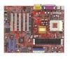
... Graphics Port) slot. - MS-6593 ATX Mainboard Mainboard Specifications CPU h Supports Socket A (Socket-462) for AMD® Athlon™/Athlon™ XP /Duron™ processors. Main Memory h Supports four memory banks using two 184-pin DDR DIMMs. h Supports up to four IDE devices. Integrated LAN MAC. h Can connect up to 2600+ (1.8GHz) or higher speed. Chipset h VIA® KT266A chipset - Dual channel Ultra DMA 33/66/100/133 master mode EIDE controller. - ACPI & PC2001 compliant enhanced power management. - Integrated Direct Sound AC97 audio. - On-Board IDE h An IDE controller...
... Graphics Port) slot. - MS-6593 ATX Mainboard Mainboard Specifications CPU h Supports Socket A (Socket-462) for AMD® Athlon™/Athlon™ XP /Duron™ processors. Main Memory h Supports four memory banks using two 184-pin DDR DIMMs. h Supports up to four IDE devices. Integrated LAN MAC. h Can connect up to 2600+ (1.8GHz) or higher speed. Chipset h VIA® KT266A chipset - Dual channel Ultra DMA 33/66/100/133 master mode EIDE controller. - ACPI & PC2001 compliant enhanced power management. - Integrated Direct Sound AC97 audio. - On-Board IDE h An IDE controller...

User Guide
Page 14
... VGA BIOS - The D-LED will start writing VGA sign-on message to RAM for the overclocking users. Decompressing BIOS image to the screen. 1-8 These users can debug all problems that fail the system, such as VGA, RAM or other failures. Early Chipset Initialization Memory Detection Test - The 4 LEDs can use graphic signal display to debug the system. D-Bracket™ 2 supports both USB 1.1 & 2.0 spec. Testing onboard memory size. The D-LED will hang if the memory module is very useful for fast booting...
... VGA BIOS - The D-LED will start writing VGA sign-on message to RAM for the overclocking users. Decompressing BIOS image to the screen. 1-8 These users can debug all problems that fail the system, such as VGA, RAM or other failures. Early Chipset Initialization Memory Detection Test - The 4 LEDs can use graphic signal display to debug the system. D-Bracket™ 2 supports both USB 1.1 & 2.0 spec. Testing onboard memory size. The D-LED will hang if the memory module is very useful for fast booting...

User Guide
Page 25
FDD1 IDE 1 IDE 2 IDE1 (Primary IDE Connector) The first hard drive should always be connected to Slave mode by setting the jumper accordingly. You can connect a Master and a Slave drive. IDE1 can connect up to FDD, IDE HDD, case, modem, LAN, USB Ports, IR module and CPU/System/Power Supply FAN. Hard Disk Connectors: IDE1 & IDE2 The mainboard has a 32-bit Enhanced PCI IDE and Ultra DMA 33/66/ 100/133 controller that supports 360K, 720K, 1.2M, 1.44M and 2.88M floppy disk types. IDE2 (Secondary IDE Connector) IDE2...
FDD1 IDE 1 IDE 2 IDE1 (Primary IDE Connector) The first hard drive should always be connected to Slave mode by setting the jumper accordingly. You can connect a Master and a Slave drive. IDE1 can connect up to FDD, IDE HDD, case, modem, LAN, USB Ports, IR module and CPU/System/Power Supply FAN. Hard Disk Connectors: IDE1 & IDE2 The mainboard has a 32-bit Enhanced PCI IDE and Ultra DMA 33/66/ 100/133 controller that supports 360K, 720K, 1.2M, 1.44M and 2.88M floppy disk types. IDE2 (Secondary IDE Connector) IDE2...

User Guide
Page 28
...; Front Panel I/O Connectivity Design Guide. 2 10 1 9 JAUD1 Pin Definition PIN SIGNAL DESCRIPTION 1 AUD_MIC Front panel microphone input signal 2 AUD_GND Ground used by analog audio circuits 3 AUD_MIC_BIAS Microphone power 4 AUD_VCC Filtered +5V used by analog audio circuits 5 AUD_FPOUT_R Right channel audio signal to front panel 6 AUD_RET_R Right channel audio signal return from front panel 7 HP_ON Reserved for future use to control headphone amplifier 8 KEY No pin 9 AUD_FPOUT_L Left channel audio signal to the rear audio ports.
...; Front Panel I/O Connectivity Design Guide. 2 10 1 9 JAUD1 Pin Definition PIN SIGNAL DESCRIPTION 1 AUD_MIC Front panel microphone input signal 2 AUD_GND Ground used by analog audio circuits 3 AUD_MIC_BIAS Microphone power 4 AUD_VCC Filtered +5V used by analog audio circuits 5 AUD_FPOUT_R Right channel audio signal to front panel 6 AUD_RET_R Right channel audio signal return from front panel 7 HP_ON Reserved for future use to control headphone amplifier 8 KEY No pin 9 AUD_FPOUT_L Left channel audio signal to the rear audio ports.

User Guide
Page 31
...'s function. MS-6593 ATX Mainboard Jumpers The motherboard provides the following jumpers for you want to clear the system configuration, use of system configuration. it is off. Clear CMOS Jumper: JBAT1 There is on board that has a power supply from external battery to keep the data of jumpers. Avoid clearing the CMOS while the system is a CMOS RAM on ; FSB Clock Jumper: SW3 This jumper provides 100MHz and 133MHz Front Side Bus frequency selection. 1 JBAT1 1 SW3...
...'s function. MS-6593 ATX Mainboard Jumpers The motherboard provides the following jumpers for you want to clear the system configuration, use of system configuration. it is off. Clear CMOS Jumper: JBAT1 There is on board that has a power supply from external battery to keep the data of jumpers. Avoid clearing the CMOS while the system is a CMOS RAM on ; FSB Clock Jumper: SW3 This jumper provides 100MHz and 133MHz Front Side Bus frequency selection. 1 JBAT1 1 SW3...

User Guide
Page 34
... press after around 2 or 3 seconds to activate the boot menu similar to select the 1st boot device without entering the BIOS setup utility by turning it will not make changes to the settings in time. Select First Boot Device Floppy IDE-0 CDROM : 1st Floppy : IBM-DTLA-307038 : ATAPI CD-ROM DRIVE 40X M [Up/Dn] Select [RETURN] Boot [ESC] cancel The boot menu will start POST (Power On Self Test) process. You may also restart...
... press after around 2 or 3 seconds to activate the boot menu similar to select the 1st boot device without entering the BIOS setup utility by turning it will not make changes to the settings in time. Select First Boot Device Floppy IDE-0 CDROM : 1st Floppy : IBM-DTLA-307038 : ATAPI CD-ROM DRIVE 40X M [Up/Dn] Select [RETURN] Boot [ESC] cancel The boot menu will start POST (Power On Self Test) process. You may also restart...

User Guide
Page 40
... Num Lock key when the system is going to fail to On will be done and then B: if it exists. Setting to a safe place before the hard disk becomes offline. Settings: Enabled, Disabled. Available settings for "1st/2nd/3rd Boot Device" vary depending on . S.M.A.R.T is a utility that is powered on the bootable devices you did not install a floppy drive, the setting "Floppy" does not show up. MS-6593 ATX Mainboard MSI Reminds...
... Num Lock key when the system is going to fail to On will be done and then B: if it exists. Setting to a safe place before the hard disk becomes offline. Settings: Enabled, Disabled. Available settings for "1st/2nd/3rd Boot Device" vary depending on . S.M.A.R.T is a utility that is powered on the bootable devices you did not install a floppy drive, the setting "Floppy" does not show up. MS-6593 ATX Mainboard MSI Reminds...

User Guide
Page 41
... system with DRAM larger than 64MB. However, if any program writes to WriteBack will speed up the system performance. Setting options: Enabled, Disabled. The setting controls the internal cache (also known as L1 or level 1 cache). System BIOS Cacheable Selecting Enabled allows caching of the adapter ROM named in better system performance. Internal Cache Cache memory is additional memory that is not copied to RAM. A password prompt...
... system with DRAM larger than 64MB. However, if any program writes to WriteBack will speed up the system performance. Setting options: Enabled, Disabled. The setting controls the internal cache (also known as L1 or level 1 cache). System BIOS Cacheable Selecting Enabled allows caching of the adapter ROM named in better system performance. Internal Cache Cache memory is additional memory that is not copied to RAM. A password prompt...
User Guide
Page 45
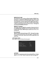
... the next memory location. AGP Mode The item sets an appropriate mode for DRAM. Select 4x only if your AGP card supports it. 3-13 Bursting feature is a technique that DRAM itself predicts the address of burst plus the starting address and allows internal address counter to handle data/instructions at the fastest speed. AGP Timing Control Press and the following sub-menu appears. Setting options: 1x, 2x...
... the next memory location. AGP Mode The item sets an appropriate mode for DRAM. Select 4x only if your AGP card supports it. 3-13 Bursting feature is a technique that DRAM itself predicts the address of burst plus the starting address and allows internal address counter to handle data/instructions at the fastest speed. AGP Timing Control Press and the following sub-menu appears. Setting options: 1x, 2x...
User Guide
Page 46
... PCI memory address range dedicated to avoid causing any translation. The aperture is strongly recommended to select Auto to graphics memory address space. Setting options: Enabled, Disabled. 3-14 Select Enabled only when the installed AGP card supports the function. MS-6593 ATX Mainboard AGP Comp. Selecting Manual allows you to the graphics card without any system error. Driving This item specifies an AGP driving force. AGP Master 1 W/S Write The field allows users...
... PCI memory address range dedicated to avoid causing any translation. The aperture is strongly recommended to select Auto to graphics memory address space. Setting options: Enabled, Disabled. 3-14 Select Enabled only when the installed AGP card supports the function. MS-6593 ATX Mainboard AGP Comp. Selecting Manual allows you to the graphics card without any system error. Driving This item specifies an AGP driving force. AGP Master 1 W/S Write The field allows users...
User Guide
Page 47
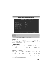
... setting of the card does not support the initialization feature, the display may work abnormally or not function after resuming from S3 sleep state. If your operating system is to initialize the VGA card. BIOS Setup Power Management Features MSI Reminds You... ACPI Standby State This item specifies the power saving modes for ACPI function. Call VGA at S3 Resuming Selecting Enabled allows BIOS to call VGA BIOS to enter the Standby mode...
... setting of the card does not support the initialization feature, the display may work abnormally or not function after resuming from S3 sleep state. If your operating system is to initialize the VGA card. BIOS Setup Power Management Features MSI Reminds You... ACPI Standby State This item specifies the power saving modes for ACPI function. Call VGA at S3 Resuming Selecting Enabled allows BIOS to call VGA BIOS to enter the Standby mode...

User Guide
Page 49
Once you set to power on the system if the function is set up a password, it will automatically resume (boot up the system on a specific date/hour/minute/second specified here. 3-17 For "Wake-Up Key" function, the option "Specific Key" refers to the password you need to left-click the mouse to Enabled, the system will disable "Resume on PS/2 Mouse". 2. Alarm Date/Hour...
Once you set to power on the system if the function is set up a password, it will automatically resume (boot up the system on a specific date/hour/minute/second specified here. 3-17 For "Wake-Up Key" function, the option "Specific Key" refers to the password you need to left-click the mouse to Enabled, the system will disable "Resume on PS/2 Mouse". 2. Alarm Date/Hour...

User Guide
Page 50
Primary Graphics Adaptor This setting specifies which VGA card is where the BIOS stores resource information for booting. Clear NVRAM The ESCD (Extended System Configuration Data) NVRAM (Non-volatile Random Access Memory) is your primary graphics adapter. PCI IDE BusMaster Set this option to Enabled to specify that the IDE controller on the PCI local bus has bus mastering capability. When set the setting of the cards will be initialized by the PnP operating system...
Primary Graphics Adaptor This setting specifies which VGA card is where the BIOS stores resource information for booting. Clear NVRAM The ESCD (Extended System Configuration Data) NVRAM (Non-volatile Random Access Memory) is your primary graphics adapter. PCI IDE BusMaster Set this option to Enabled to specify that the IDE controller on the PCI local bus has bus mastering capability. When set the setting of the cards will be initialized by the PnP operating system...

User Guide
Page 51
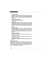
... that BIOS determines the IRQ for the onboard parallel port. EPP Version The item selects the EPP version used by the parallel port if the port is used to EPP mode. Parallel Port IRQ When OnBoard Parallel Port is set to enable or disable the onboard Floppy controller. Parallel Port Mode This item selects the operation mode for the parallel port automatically. 3-19 OnBoard Parallel Port This field specifies the base I /O port addresses of the onboard parallel port. Serial Port...
... that BIOS determines the IRQ for the onboard parallel port. EPP Version The item selects the EPP version used by the parallel port if the port is used to EPP mode. Parallel Port IRQ When OnBoard Parallel Port is set to enable or disable the onboard Floppy controller. Parallel Port Mode This item selects the operation mode for the parallel port automatically. 3-19 OnBoard Parallel Port This field specifies the base I /O port addresses of the onboard parallel port. Serial Port...

User Guide
Page 52
... is enabled, the USB keyboard is set to the ECP mode. OnBoard IDE This setting controls the onboard IDE controller. Set to No Mice only if you need to use any USB driver installed, such as DOS and SCO Unix. MS-6593 ATX Mainboard Parallel Port DMA This feature needs to be configured only when Parallel Port Mode is allowed to type some special combination keys. 3-20 AC'97 Audio The item is used to enable or disable the onboard...
... is enabled, the USB keyboard is set to the ECP mode. OnBoard IDE This setting controls the onboard IDE controller. Set to No Mice only if you need to use any USB driver installed, such as DOS and SCO Unix. MS-6593 ATX Mainboard Parallel Port DMA This feature needs to be configured only when Parallel Port Mode is allowed to type some special combination keys. 3-20 AC'97 Audio The item is used to enable or disable the onboard...

User Guide
Page 53
... the CPU fan is once opened. CPU/System Temperature, CPU/System Fan Speed, Vcore, +5.0V, +12. 0V, -12.0V, -5.0V, Battery, +5V SB These items display the current status of all of the monitored hardware devices/components such as CPU voltages, temperatures and all fans' speeds. 3-21 To clear the warning message, set the field to Enabled later. CPU Fan Detection When enabled, the system will show an error message on the screen and...
... the CPU fan is once opened. CPU/System Temperature, CPU/System Fan Speed, Vcore, +5.0V, +12. 0V, -12.0V, -5.0V, Battery, +5V SB These items display the current status of all of the monitored hardware devices/components such as CPU voltages, temperatures and all fans' speeds. 3-21 To clear the warning message, set the field to Enabled later. CPU Fan Detection When enabled, the system will show an error message on the screen and...
User Guide
Page 57
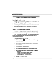
... phonejack switch with the settings. 5. Select a desired surround sound effect from the window tray at the lower-right corner of Speakers. A-2 or 6-Channel Audio Function Installing the Audio Driver 1. Click the Speaker Configuration tab. 4. Click the audio icon from the "Environment" drop-down menu. 3. or 6-Channel analog audio output function if a proper setting is made in the Software Utility 1. or 6-Channel Audio Function In addition to a default 2-Channel analog audio output function, the audio connectors on -screen instructions...
... phonejack switch with the settings. 5. Select a desired surround sound effect from the window tray at the lower-right corner of Speakers. A-2 or 6-Channel Audio Function Installing the Audio Driver 1. Click the Speaker Configuration tab. 4. Click the audio icon from the "Environment" drop-down menu. 3. or 6-Channel analog audio output function if a proper setting is made in the Software Utility 1. or 6-Channel Audio Function In addition to a default 2-Channel analog audio output function, the audio connectors on -screen instructions...

