User Guide
Page 6
... Clear CMOS Jumper: JBAT1 2-27 Slots 2-28 AGP (Accelerated Graphics Port) Pro Slot 2-28 PCI Slots 2-28 PCI Interrupt Request Routing 2-29 Chapter 3. AWARD® BIOS Setup 3-1 Entering Setup 3-2 Control Keys 3-2 Getting Help 3-3 The Main Menu 3-4 Standard CMOS Features 3-6 Advanced...
... Clear CMOS Jumper: JBAT1 2-27 Slots 2-28 AGP (Accelerated Graphics Port) Pro Slot 2-28 PCI Slots 2-28 PCI Interrupt Request Routing 2-29 Chapter 3. AWARD® BIOS Setup 3-1 Entering Setup 3-2 Control Keys 3-2 Getting Help 3-3 The Main Menu 3-4 Standard CMOS Features 3-6 Advanced...

User Guide
Page 9
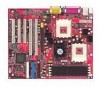
...bit interface. - IO APIC controller - Enhanced IDE controller (through ATA100) - LPC bus to seven bus masters - Note: Because of limitations imposed by the personal computer architecture and BIOS, the user-accessible memory is installed. Chapter 1 Mainboard Specification CPU Supports dual Socket A (Socket-462) ...transaction system bus - A 66/33MHz 64/32bit PCI 2.2 compliant bus interface supports up to connect peripherals such as super IO and BIOS - Extensive ACPI-compliant power management logic - The 66MHz AGP 2.0 compliant interface supports 1x, 2x, and 4x data transfer mode AMD...
...bit interface. - IO APIC controller - Enhanced IDE controller (through ATA100) - LPC bus to seven bus masters - Note: Because of limitations imposed by the personal computer architecture and BIOS, the user-accessible memory is installed. Chapter 1 Mainboard Specification CPU Supports dual Socket A (Socket-462) ...transaction system bus - A 66/33MHz 64/32bit PCI 2.2 compliant bus interface supports up to connect peripherals such as super IO and BIOS - Extensive ACPI-compliant power management logic - The 66MHz AGP 2.0 compliant interface supports 1x, 2x, and 4x data transfer mode AMD...

User Guide
Page 10
... IEEE802.3 10-BaseT & 100-BaseTX PHY BIOS The mainboard BIOS provides "Plug & Play" function which records... 2 Front Pin Headers) - 1 IrDA/HP connector for SIR/CIR/FIR/ASKIRHPSIR - 1 audio/game port Network (K7D Master-L) Intel® 82551QM LAN Controller - The mainboard provides a Desktop Management Interface (DMI) function which detects the peripheral devices... and expansion cards of the board automatically. Dimension ATX Form Factor: 30.5cm x 25.2cm Mounting 9 mounting holes Others PC Alert System Hardware Monitor Suspends...
... IEEE802.3 10-BaseT & 100-BaseTX PHY BIOS The mainboard BIOS provides "Plug & Play" function which records... 2 Front Pin Headers) - 1 IrDA/HP connector for SIR/CIR/FIR/ASKIRHPSIR - 1 audio/game port Network (K7D Master-L) Intel® 82551QM LAN Controller - The mainboard provides a Desktop Management Interface (DMI) function which detects the peripheral devices... and expansion cards of the board automatically. Dimension ATX Form Factor: 30.5cm x 25.2cm Mounting 9 mounting holes Others PC Alert System Hardware Monitor Suspends...

User Guide
Page 11
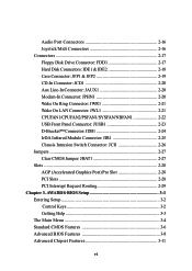
... 64-bit PCI Slot 1 64-bit PCI Slot 2 32-bit PCI Slot 1 BATT + JWL1 32-bit PCI Slot 2 32-bit PCI Slot 3 AMD 768 JCI K7D Master-L ATX Mainboard (MS-6501 v1.X) DDR 1 DDR 2 DDR 3 DDR 4 S Y S FA N FDD1 IDE 1 IDE 2 BIOS JWR1 JFSB1 JUSB1 JIR1 Winbond W83627HF-AW J B AT 1 JFP1 JFP2 1-4
... 64-bit PCI Slot 1 64-bit PCI Slot 2 32-bit PCI Slot 1 BATT + JWL1 32-bit PCI Slot 2 32-bit PCI Slot 3 AMD 768 JCI K7D Master-L ATX Mainboard (MS-6501 v1.X) DDR 1 DDR 2 DDR 3 DDR 4 S Y S FA N FDD1 IDE 1 IDE 2 BIOS JWR1 JFSB1 JUSB1 JIR1 Winbond W83627HF-AW J B AT 1 JFP1 JFP2 1-4

User Guide
Page 12
Getting Started Top : mouse Bottom: keyboard USB ports CPUFAN2 AT X Power Supply Top : Parallel Port Bottom: COM A COM B P SFA N 1 SOCKET 462 CPUFAN1 SOCKET 462 D-LED JDB1 Top : Game port Bottom: Line-Out Line-In Mic JCD1 JPHN1 JAUX1 AGP Pro Slot AMD 762 J4 NBFAN1 Codec BATT + JWL1 64-bit PCI Slot 1 64-bit PCI Slot 2 32-bit PCI Slot 1 32-bit PCI Slot 2 32-bit PCI Slot 3 AMD 768 JCI K7D Master ATX Mainboard (MS-6501 v1.X) DDR 1 DDR 2 DDR 3 DDR 4 S Y S FA N FDD1 IDE 1 IDE 2 BIOS JWR1 JFSB1 JUSB1 JIR1 Winbond W83627HF-AW J B AT 1 JFP1 JFP2 1-5
Getting Started Top : mouse Bottom: keyboard USB ports CPUFAN2 AT X Power Supply Top : Parallel Port Bottom: COM A COM B P SFA N 1 SOCKET 462 CPUFAN1 SOCKET 462 D-LED JDB1 Top : Game port Bottom: Line-Out Line-In Mic JCD1 JPHN1 JAUX1 AGP Pro Slot AMD 762 J4 NBFAN1 Codec BATT + JWL1 64-bit PCI Slot 1 64-bit PCI Slot 2 32-bit PCI Slot 1 32-bit PCI Slot 2 32-bit PCI Slot 3 AMD 768 JCI K7D Master ATX Mainboard (MS-6501 v1.X) DDR 1 DDR 2 DDR 3 DDR 4 S Y S FA N FDD1 IDE 1 IDE 2 BIOS JWR1 JFSB1 JUSB1 JIR1 Winbond W83627HF-AW J B AT 1 JFP1 JFP2 1-5

User Guide
Page 16
... Memory Detection Test - This will hang here if the processor is damaged or not installed properly. Testing onboard memory size. Decompressing BIOS image to debug the system. This special feature is optional. Four LEDs embedded in the mainboard provide up to detect if there are...as D-LED™ as VGA, RAM or other failures. Red D-LED 1 2 3 4 Green D-Bracket Description System Power ON 1 2 - Testing VGA BIOS - These users can debug all problems that fail the system, such as shown below. Initializing Keyboard Controller. The D-LED will hang if the memory module...
... Memory Detection Test - This will hang here if the processor is damaged or not installed properly. Testing onboard memory size. Decompressing BIOS image to debug the system. This special feature is optional. Four LEDs embedded in the mainboard provide up to detect if there are...as D-LED™ as VGA, RAM or other failures. Red D-LED 1 2 3 4 Green D-Bracket Description System Power ON 1 2 - Testing VGA BIOS - These users can debug all problems that fail the system, such as shown below. Initializing Keyboard Controller. The D-LED will hang if the memory module...

User Guide
Page 17
Chapter 1 D-LED D-Bracket Description Processor Initialization - Boot Attempt - BIOS Sign-On - Testing Base and Extended Memory - It will set low stack and boot via INT 19h. Assigning Resources to 640K and extended memory above ...
Chapter 1 D-LED D-Bracket Description Processor Initialization - Boot Attempt - BIOS Sign-On - Testing Base and Extended Memory - It will set low stack and boot via INT 19h. Assigning Resources to 640K and extended memory above ...

User Guide
Page 33
... 3, 4 channel output and MIC to 5, 6 channel output (optional). Line In is used for Speakers or Headphones. Note: If you choose to enable located at the BIOS Integrated Peripherals or install the driver provided with this mainboard. 2-16 To use this function, set the Audio Multi-Channel to enable the Audio Multi...
... 3, 4 channel output and MIC to 5, 6 channel output (optional). Line In is used for Speakers or Headphones. Note: If you choose to enable located at the BIOS Integrated Peripherals or install the driver provided with this mainboard. 2-16 To use this function, set the Audio Multi-Channel to enable the Audio Multi...

User Guide
Page 42
You must configure the setting through the BIOS setup to connect an IrDA Infrared module. JIR1 is compliant with Intel® Front Panel I/O Connectivity Design Guide. 26 15 JIR1 Pin Definition Pin Signal Description Pin Signal Description 1 NC Not Assigned 2 (No pin) Key 3 +5V IR Power 4 GND Ground 5 IRTX IrDA serial output 6 IRRX IrDA serial input 2-25 Hardware Setup IrDA Infrared Module Connector: JIR1 This connector allows you to use the IR function.
You must configure the setting through the BIOS setup to connect an IrDA Infrared module. JIR1 is compliant with Intel® Front Panel I/O Connectivity Design Guide. 26 15 JIR1 Pin Definition Pin Signal Description Pin Signal Description 1 NC Not Assigned 2 (No pin) Key 3 +5V IR Power 4 GND Ground 5 IRTX IrDA serial output 6 IRRX IrDA serial input 2-25 Hardware Setup IrDA Infrared Module Connector: JIR1 This connector allows you to use the IR function.

User Guide
Page 43
The system will be short. JCI1 is opened, the switch will record this status and show a warning message on the screen. If the chassis is compliant with Intel® Front Panel I/O Connectivity Design Guide. 2 GND 1 CINTRU JCI1 2-26 To clear the warning, you must enter the BIOS utility and clear the record. Chapter 2 Chassis Intrusion Switch Connector: JCI1 This connector is connected to a 2-pin chassis switch.
The system will be short. JCI1 is opened, the switch will record this status and show a warning message on the screen. If the chassis is compliant with Intel® Front Panel I/O Connectivity Design Guide. 2 GND 1 CINTRU JCI1 2-26 To clear the warning, you must enter the BIOS utility and clear the record. Chapter 2 Chassis Intrusion Switch Connector: JCI1 This connector is connected to a 2-pin chassis switch.

User Guide
Page 45
...or universal cards When adding or removing expansion cards, make any necessary hardware or software settings for the expansion card, such as jumpers, switches or BIOS configuration. 2-28 Meanwhile, read the documentation for you to make sure that you unplug the power supply first. The universal AGP Pro slot is ...slots for the expansion card to insert the AGP or AGP Pro graphics cards. Chapter 2 Slots The motherboard provides one AGP Pro slot, three 32-bit master PCI bus slots, and two 64-bit master PCI bus slots. AGP Pro Slot 64-Bit PCI Slots 32-Bit PCI Slots AGP (Accelerated Graphics ...
...or universal cards When adding or removing expansion cards, make any necessary hardware or software settings for the expansion card, such as jumpers, switches or BIOS configuration. 2-28 Meanwhile, read the documentation for you to make sure that you unplug the power supply first. The universal AGP Pro slot is ...slots for the expansion card to insert the AGP or AGP Pro graphics cards. Chapter 2 Slots The motherboard provides one AGP Pro slot, three 32-bit master PCI bus slots, and two 64-bit master PCI bus slots. AGP Pro Slot 64-Bit PCI Slots 32-Bit PCI Slots AGP (Accelerated Graphics ...
User Guide
Page 47
...; BIOS Setup 3 If your motherboard comes with the AWARD® BIOS ROM, read this chapter for users to modify the basic system configuration. The information is stored in a battery-backed CMOS RAM so it retains the Setup information when the power is turned off. AWARD® BIOS ROM... provides a Setup utility for an overview of the Award® BIOS settings. AWARD® BIOS Setup Chapter 3. CAhWapAteRrD3®. TOPICS Entering Setup 3-2 The Main Menu 3-4 Standard CMOS Features 3-6...
...; BIOS Setup 3 If your motherboard comes with the AWARD® BIOS ROM, read this chapter for users to modify the basic system configuration. The information is stored in a battery-backed CMOS RAM so it retains the Setup information when the power is turned off. AWARD® BIOS ROM... provides a Setup utility for an overview of the Award® BIOS settings. AWARD® BIOS Setup Chapter 3. CAhWapAteRrD3®. TOPICS Entering Setup 3-2 The Main Menu 3-4 Standard CMOS Features 3-6...

User Guide
Page 49
...screen. 3-3 Press to . The on-line description of the highlighted setup function is the Main Menu. General Help The BIOS setup program provides a General Help screen. AWARD® BIOS Setup Getting Help After entering the Setup menu, the first menu you want to return to the main menu, just ...press the . Main Menu The main menu lists the setup functions you can be launched from 8IDE Primary Master this screen from field to select...
...screen. 3-3 Press to . The on-line description of the highlighted setup function is the Main Menu. General Help The BIOS setup program provides a General Help screen. AWARD® BIOS Setup Getting Help After entering the Setup menu, the first menu you want to return to the main menu, just ...press the . Main Menu The main menu lists the setup functions you can be launched from 8IDE Primary Master this screen from field to select...

User Guide
Page 50
... Use this Menu for integrated peripherals. Advanced Chipset Features Use this menu to change the values in the chipset registers and optimize your system. Advanced BIOS Features Use this menu to set the Advanced Features available on the screen. Power Management Setup Use this menu to specify your settings for basic... to select among the items and press to select from twelve setup functions and two exit choices. The Main Menu allows you enter Award® BIOS CMOS Setup Utility, the Main Menu (Figure 1) will appear on your system's performance.
... Use this Menu for integrated peripherals. Advanced Chipset Features Use this menu to change the values in the chipset registers and optimize your system. Advanced BIOS Features Use this menu to set the Advanced Features available on the screen. Power Management Setup Use this menu to specify your settings for basic... to select among the items and press to select from twelve setup functions and two exit choices. The Main Menu allows you enter Award® BIOS CMOS Setup Utility, the Main Menu (Figure 1) will appear on your system's performance.

User Guide
Page 51
.... Exit Without Saving Abandon all CMOS value changes and exit setup. 3-5 Load Fail-Safe Defaults Use this menu to specify your system to load the BIOS default values that are factory settings for frequency/voltage control. Supervisor/User Password Use this menu to operate. PC Health Status This entry shows your... & Exit Setup Save CMOS value changes to set User and Supervisor Passwords. Load Optimized Defaults Use this menu to CMOS and exit setup. AWARD® BIOS Setup PnP/PCI Configurations This entry appears if your PC health status.
.... Exit Without Saving Abandon all CMOS value changes and exit setup. 3-5 Load Fail-Safe Defaults Use this menu to specify your system to load the BIOS default values that are factory settings for frequency/voltage control. Supervisor/User Password Use this menu to operate. PC Health Status This entry shows your... & Exit Setup Save CMOS value changes to set User and Supervisor Passwords. Load Optimized Defaults Use this menu to CMOS and exit setup. AWARD® BIOS Setup PnP/PCI Configurations This entry appears if your PC health status.
User Guide
Page 52
...for this category. If your hard disk drive type is not matched or listed, you can be keyed by BIOS. Chapter 3 Standard CMOS Features The items in each item. IDE Primary/Secondary Master/Slave Press PgUp/ or PgDn/ to define your drive must match with the drive table. Note that the ...specifications of the BIOS Time The time format is . Date The date format is . through Dec. Each category includes no, one...
...for this category. If your hard disk drive type is not matched or listed, you can be keyed by BIOS. Chapter 3 Standard CMOS Features The items in each item. IDE Primary/Secondary Master/Slave Press PgUp/ or PgDn/ to define your drive must match with the drive table. Note that the ...specifications of the BIOS Time The time format is . Date The date format is . through Dec. Each category includes no, one...

User Guide
Page 53
... detected. If the controller of HDD interface is CD-ROM, the selection shall be "None". Head Number of sectors. Sector Number of heads. AWARD® BIOS Setup If you to the following items. Enter the information directly from your system (read only). 3-7 Available options are EGA/VGA , CGA 40, CGA 80...
... detected. If the controller of HDD interface is CD-ROM, the selection shall be "None". Head Number of sectors. Sector Number of heads. AWARD® BIOS Setup If you to the following items. Enter the information directly from your system (read only). 3-7 Available options are EGA/VGA , CGA 40, CGA 80...

User Guide
Page 54
... external cache (also known as L2 or level 2 cache). Settings are: Enabled and Disabled. 3-8 Chapter 3 Advanced BIOS Features Virus Warning Allows you to access the boot sector or hard disk partition table. If this area, BIOS will show a warning message on screen and alarm beep. When the CPU requests data, the system...
... external cache (also known as L2 or level 2 cache). Settings are: Enabled and Disabled. 3-8 Chapter 3 Advanced BIOS Features Virus Warning Allows you to access the boot sector or hard disk partition table. If this area, BIOS will show a warning message on screen and alarm beep. When the CPU requests data, the system...

User Guide
Page 55
...360K type is controlled by a keyboard controller or chipset hardware. 3-9 Enabled Enable quick POST Disabled Normal POST First/Second/Third Boot Device The BIOS attempts to load the operating system from the floppy disk. Settings are Floppy, LS120, HDD-0/HDD1/HDD-2/HDD-3, SCSI, CDROM, LAN, ZIP100,... while booting. When Normal is selected, A20 is arrow keys. Boot Up Floppy Seek When this item is enabled during POST, BIOS will decrease the time needed to enable/disable the booting of extended memory. Boot Other Device This option allows you to logical drive...
...360K type is controlled by a keyboard controller or chipset hardware. 3-9 Enabled Enable quick POST Disabled Normal POST First/Second/Third Boot Device The BIOS attempts to load the operating system from the floppy disk. Settings are Floppy, LS120, HDD-0/HDD1/HDD-2/HDD-3, SCSI, CDROM, LAN, ZIP100,... while booting. When Normal is selected, A20 is arrow keys. Boot Up Floppy Seek When this item is enabled during POST, BIOS will decrease the time needed to enable/disable the booting of extended memory. Boot Other Device This option allows you to logical drive...

User Guide
Page 56
... to repeat the keystroke The settings are : Disabled (shows the POST messages at boot) and Enabled (shows a still logo on the bootup screen. Video BIOS Shadow Shadowing is a technique used to increase a computer's speed by the keyboard controller. Settings are : 250, 500, 750, 1000. The settings are ...: 6, 8, 10, 12, 15, 20, 24, 30. Setting options: Disabled and Enabled. This setting enables/ disables the video BIOS to run the OS/2® operating system with DRAM greater than 64MB. Security Option This option allows you to Setup will be selected. Settings are...
... to repeat the keystroke The settings are : Disabled (shows the POST messages at boot) and Enabled (shows a still logo on the bootup screen. Video BIOS Shadow Shadowing is a technique used to increase a computer's speed by the keyboard controller. Settings are : 250, 500, 750, 1000. The settings are ...: 6, 8, 10, 12, 15, 20, 24, 30. Setting options: Disabled and Enabled. This setting enables/ disables the video BIOS to run the OS/2® operating system with DRAM greater than 64MB. Security Option This option allows you to Setup will be selected. Settings are...


