
User Guide
Page 2
... All trademarks are registered trademarks of Intel Corporation. Alternatively, please try the following help resources for FAQ, technical guide, BIOS updates, driver updates, and other countries. Intel® and Pentium® are the properties of their respective owners. Award...indows® 2000/XP/Vista are registered trademarks of International Business Machines Corporation. func=faqIndex Contact our technical staff at: http://support.msi.com.tw/ ii We take every care in the preparation of this document is the intellectual property of M ICRO-STAR INTERNATIONAL. Our...
... All trademarks are registered trademarks of Intel Corporation. Alternatively, please try the following help resources for FAQ, technical guide, BIOS updates, driver updates, and other countries. Intel® and Pentium® are the properties of their respective owners. Award...indows® 2000/XP/Vista are registered trademarks of International Business Machines Corporation. func=faqIndex Contact our technical staff at: http://support.msi.com.tw/ ii We take every care in the preparation of this document is the intellectual property of M ICRO-STAR INTERNATIONAL. Our...
User Guide
Page 8
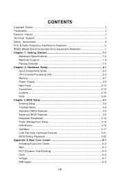
... Setup 2-1 Quick Components Guide 2-2 CPU (Central Processing Unit 2-3 Memory ...2-7 Power Supply ...2-9 Back Panel ...2-10 Connectors ...2-12 Jumpers ...2-19 Slots ...2-20 Chapter 3 BIOS Setup 3-1 Entering Setup ...3-2 The Main Menu ...3-4 Standard CMOS Features 3-6 Advanced BIOS Features 3-9 Integrated Peripherals 3-12 Power Management Setup 3-14 H/W Monitor ...3-16 Cell Menu ...3-17 Load Fail-Safe/ Optimized Defaults 3-21...
... Setup 2-1 Quick Components Guide 2-2 CPU (Central Processing Unit 2-3 Memory ...2-7 Power Supply ...2-9 Back Panel ...2-10 Connectors ...2-12 Jumpers ...2-19 Slots ...2-20 Chapter 3 BIOS Setup 3-1 Entering Setup ...3-2 The Main Menu ...3-4 Standard CMOS Features 3-6 Advanced BIOS Features 3-9 Integrated Peripherals 3-12 Power Management Setup 3-14 H/W Monitor ...3-16 Cell Menu ...3-17 Load Fail-Safe/ Optimized Defaults 3-21...

User Guide
Page 9
Temperature ...A-9 User Profile ...A-10 Appendix B Intel ICH7R SATA RAID B-1 ICH7R Introduction B-2 BIOS Configuration B-3 Installing Software B-9 RAID Migration Instructions B-15 Degraded RAID Array B-22 ix
Temperature ...A-9 User Profile ...A-10 Appendix B Intel ICH7R SATA RAID B-1 ICH7R Introduction B-2 BIOS Configuration B-3 Installing Software B-9 RAID Migration Instructions B-15 Degraded RAID Array B-22 ix

User Guide
Page 20
... retention tab. 10. Align the holes on the mainboard with the plastic cap covered (shown in Figure 1) to fasten the cooler. Mainboard photos shown in BIOS (Chapter 3). 2. Read the CPU status in this section are correctly inserted. MS-7528 Mainboard 9. Then rotate the locking switch (refer to the correct direction marked...
... retention tab. 10. Align the holes on the mainboard with the plastic cap covered (shown in Figure 1) to fasten the cooler. Mainboard photos shown in BIOS (Chapter 3). 2. Read the CPU status in this section are correctly inserted. MS-7528 Mainboard 9. Then rotate the locking switch (refer to the correct direction marked...
User Guide
Page 28
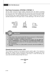
... GND 12 JCI1 2-14 W hen connecting the wire to the +12V; CPUFAN1 / SYSFAN1 / SYSFAN2 supports fan control. To clear the warning, you must enter the BIOS utility and clear the record. The system will record this status and show a warning message on -board, you must use a specially designed fan with speed... proper CPU cooling fan. 2. If the chassis is opened, the chassis intrusion mechanism will automatically control the CPU fan speed according to take advantage of BIOS and install Dual Core Center utility that the red wire is Ground and should be connected to GND.
... GND 12 JCI1 2-14 W hen connecting the wire to the +12V; CPUFAN1 / SYSFAN1 / SYSFAN2 supports fan control. To clear the warning, you must enter the BIOS utility and clear the record. The system will record this status and show a warning message on -board, you must use a specially designed fan with speed... proper CPU cooling fan. 2. If the chassis is opened, the chassis intrusion mechanism will automatically control the CPU fan speed according to take advantage of BIOS and install Dual Core Center utility that the red wire is Ground and should be connected to GND.
User Guide
Page 34
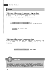
... adding or removing expansion cards, make sure that comply with PCI specifications. Meanwhile, read the documentation for the expansion card, such as jumpers, switches or BIOS configuration. 2-20 The PCI Express x 16 slot supports up to configure any necessary hardware or software settings for the expansion card to 250 MB/s transfer...
... adding or removing expansion cards, make sure that comply with PCI specifications. Meanwhile, read the documentation for the expansion card, such as jumpers, switches or BIOS configuration. 2-20 The PCI Express x 16 slot supports up to configure any necessary hardware or software settings for the expansion card to 250 MB/s transfer...
User Guide
Page 36
You may need to run the Setup program when: ² An error message appears on the BIOS Setup program and allows you to run SETUP. ² You want to configure the system for customized features. 3-1 Chapter 3 BIOS Setup BIOS Setup This chapter provides information on the screen during the system booting up, and requests you to change the default settings for optimum use.
You may need to run the Setup program when: ² An error message appears on the BIOS Setup program and allows you to run SETUP. ² You want to configure the system for customized features. 3-1 Chapter 3 BIOS Setup BIOS Setup This chapter provides information on the screen during the system booting up, and requests you to change the default settings for optimum use.

User Guide
Page 37
... keys. The items under continuous update for reference only. 2. Upon boot-up, the 1st line appearing after the memory count is usually in this BIOS was released. 3-2 Therefore, the description may also restart the system by turning it OFF and On or pressing the RESET button. It is the... BIOS version. You may be slightly different from the latest BIOS and should be held for better system performance. Important 1. MS-7528 Mainboard Entering Setup Power on the screen, ...
... keys. The items under continuous update for reference only. 2. Upon boot-up, the 1st line appearing after the memory count is usually in this BIOS was released. 3-2 Therefore, the description may also restart the system by turning it OFF and On or pressing the RESET button. It is the... BIOS version. You may be slightly different from the latest BIOS and should be held for better system performance. Important 1. MS-7528 Mainboard Entering Setup Power on the screen, ...
User Guide
Page 38
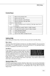
... the Main Menu. You can use arrow keys ( ↑↓ ) to highlight the field and press to call up the sub-menu. General Help The BIOS setup program provides a General Help screen. The Help screen lists the appropriate keys to use the arrow keys ( ↑↓ ) to select the item. ...You can call up this field. BIOS Setup Control Keys Enter> Move to the previous item Move to the next item Move to the item in the right hand Select the item...
... the Main Menu. You can use arrow keys ( ↑↓ ) to highlight the field and press to call up the sub-menu. General Help The BIOS setup program provides a General Help screen. The Help screen lists the appropriate keys to use the arrow keys ( ↑↓ ) to select the item. ...You can call up this field. BIOS Setup Control Keys Enter> Move to the previous item Move to the next item Move to the item in the right hand Select the item...
User Guide
Page 39
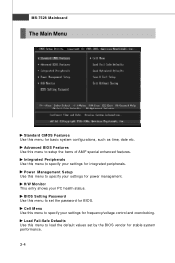
... Use this menu to specify your settings for stable system performance. 3-4 H/W Monitor This entry shows your settings for BIOS. Load Fail-Safe Defaults Use this menu to specify your PC health status. Advanced BIOS Features Use this menu to load the default values set the password for integrated peripherals. Cell Menu Use...
... Use this menu to specify your settings for stable system performance. 3-4 H/W Monitor This entry shows your settings for BIOS. Load Fail-Safe Defaults Use this menu to specify your PC health status. Advanced BIOS Features Use this menu to load the default values set the password for integrated peripherals. Cell Menu Use...

User Guide
Page 40
Exit Without Saving Abandon all changes and exit setup. 3-5 BIOS Setup Load Optimized Defaults Use this menu to CMOS and exit setup. Save & Exit Setup Save changes to load the default values set by the mainboard manufacturer specifically for optimal performance of the mainboard.
Exit Without Saving Abandon all changes and exit setup. 3-5 BIOS Setup Load Optimized Defaults Use this menu to CMOS and exit setup. Save & Exit Setup Save changes to load the default values set by the mainboard manufacturer specifically for optimal performance of the mainboard.

User Guide
Page 41
... can be adjusted by numeric function keys. day Day of the week, from Jan. IDE Primary Master/ Slave, SATA 1/2/3/4 Channel Press to Sat, determined by BIOS. Time (HH:MM :SS) This allows you to 31 can be keyed by users. The time format is . Read-only.
... can be adjusted by numeric function keys. day Day of the week, from Jan. IDE Primary Master/ Slave, SATA 1/2/3/4 Channel Press to Sat, determined by BIOS. Time (HH:MM :SS) This allows you to 31 can be keyed by users. The time format is . Read-only.
User Guide
Page 42
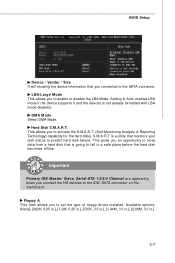
... offline. Available options: [None], [360K, 5.25 in.], [1.2M, 5.25 in.], [720K, 3.5 in.], [1.44M, 3.5 in.], [2.88M, 3.5 in.]. 3-7 Floppy A This item allows you to the SATA connector. BIOS Setup Device / Vender / Size It will showing the device information that you connected to set the type of floppy drives installed. This allows you to...
... offline. Available options: [None], [360K, 5.25 in.], [1.2M, 5.25 in.], [720K, 3.5 in.], [1.44M, 3.5 in.], [2.88M, 3.5 in.]. 3-7 Floppy A This item allows you to the SATA connector. BIOS Setup Device / Vender / Size It will showing the device information that you connected to set the type of floppy drives installed. This allows you to...
User Guide
Page 43
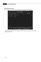
MS-7528 Mainboard System Information Press to enter the sub-menu, and the following screen appears. This sub-menu shows the CPU information, BIOS version and memory status of your system (read only). 3-8
MS-7528 Mainboard System Information Press to enter the sub-menu, and the following screen appears. This sub-menu shows the CPU information, BIOS version and memory status of your system (read only). 3-8
User Guide
Page 44
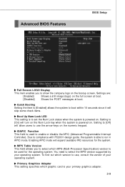
.... Setting to [On] will expand available IRQ resources for the operating system. You need to use the arrow keys on the bootup screen. Advanced BIOS Features BIOS Setup Full Screen LOGO Display This item enables you to select which MPS (Multi-Processor Specification) version to be used to enable or disable the...
.... Setting to [On] will expand available IRQ resources for the operating system. You need to use the arrow keys on the bootup screen. Advanced BIOS Features BIOS Setup Full Screen LOGO Display This item enables you to select which MPS (Multi-Processor Specification) version to be used to enable or disable the...
User Guide
Page 45
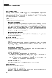
... graphics core.. [Fixed] mode, a fixed-size fragment of the system memory is part of the chipset. W hen set the first/ second/ third boot device where BIOS attempts to load the disk operating system. 3-10 Set Limit CPUID MaxVal to 3 The Max CPUID Value Limit is designed to limit the listed speed...
... graphics core.. [Fixed] mode, a fixed-size fragment of the system memory is part of the chipset. W hen set the first/ second/ third boot device where BIOS attempts to load the disk operating system. 3-10 Set Limit CPUID MaxVal to 3 The Max CPUID Value Limit is designed to limit the listed speed...
User Guide
Page 46
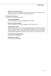
...: TCG/TPM SUPPORT This setting allows you to clear the user information in the TPM security chip. TPM Owner Status This item is not configurable. BIOS Setup Boot From Other Device Setting the option to [Yes] allows the system to try to enable/disable the TCG/TPM. if the system fails...
...: TCG/TPM SUPPORT This setting allows you to clear the user information in the TPM security chip. TPM Owner Status This item is not configurable. BIOS Setup Boot From Other Device Setting the option to [Yes] allows the system to try to enable/disable the TCG/TPM. if the system fails...
User Guide
Page 47
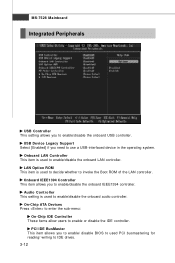
...: On-Chip IDE Controller These items allow users to enable/disable the onboard IEEE1394 controller. PCI IDE BusMaster This item allows you to enable/ disable BIOS to used to IDE drives. 3-12 Onboard LAN Controller This item is used PCI busmastering for reading/ writing to enable/disable the onboard LAN controller...
...: On-Chip IDE Controller These items allow users to enable/disable the onboard IEEE1394 controller. PCI IDE BusMaster This item allows you to enable/ disable BIOS to used to IDE drives. 3-12 Onboard LAN Controller This item is used PCI busmastering for reading/ writing to enable/disable the onboard LAN controller...
User Guide
Page 48
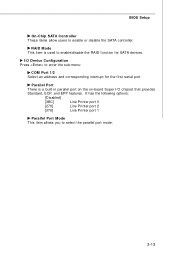
... used to enter the sub-menu: COM Port 1/2 Select an address and corresponding interrupt for SATA devices. I /O chipset that provides Standard, ECP, and EPP features. BIOS Setup On-Chip SATA Controller These items allow users to select the parallel port mode. 3-13 RAID Mode This item is a built-in parallel port...
... used to enter the sub-menu: COM Port 1/2 Select an address and corresponding interrupt for SATA devices. I /O chipset that provides Standard, ECP, and EPP features. BIOS Setup On-Chip SATA Controller These items allow users to select the parallel port mode. 3-13 RAID Mode This item is a built-in parallel port...
User Guide
Page 49
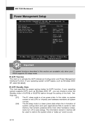
... Standby mode in memory will be used to save energy. ACPI Standby State This item specifies the power saving modes for ACPI function. If your BIOS supports S3 sleep mode. In this section are available only when your operating system supports ACPI, such as W indows 2000/ XP, select [Enabled]. Settings are...
... Standby mode in memory will be used to save energy. ACPI Standby State This item specifies the power saving modes for ACPI function. If your BIOS supports S3 sleep mode. In this section are available only when your operating system supports ACPI, such as W indows 2000/ XP, select [Enabled]. Settings are...


