
User Guide
Page 2
... for FAQ, technical guide, BIOS updates, driver updates, and other countries. We take every care in the preparation of this document is the intellectual property of M ICRO-STAR INTERNATIONAL. PS/2 and OS®/2 are registered trademarks of Intel Corporation. Copyright Notice The material in this document, but no solution can be obtained from the user's manual, please contact...
... for FAQ, technical guide, BIOS updates, driver updates, and other countries. We take every care in the preparation of this document is the intellectual property of M ICRO-STAR INTERNATIONAL. PS/2 and OS®/2 are registered trademarks of Intel Corporation. Copyright Notice The material in this document, but no solution can be obtained from the user's manual, please contact...
User Guide
Page 8
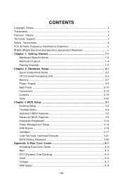
...CPU (Central Processing Unit 2-3 Memory ...2-7 Power Supply ...2-9 Back Panel ...2-10 Connectors ...2-12 Jumpers ...2-19 Slots ...2-20 Chapter 3 BIOS Setup 3-1 Entering Setup ...3-2 The Main Menu ...3-4 Standard CMOS Features 3-6 Advanced BIOS Features 3-9 Integrated Peripherals 3-12 Power Management Setup 3-14 H/W Monitor ...3-16 Cell Menu ...3-17 Load Fail-Safe/ Optimized Defaults 3-21 BIOS Setting Password 3-22 Appendix A Dual Core Center A-1 Activating Dual Core Center A-2 Main ...A-3 DOT (Dynamic OverClocking A-5 Clock ...A-6 Voltage ...A-7 FAN Speed ...A-8 viii Getting Started...
...CPU (Central Processing Unit 2-3 Memory ...2-7 Power Supply ...2-9 Back Panel ...2-10 Connectors ...2-12 Jumpers ...2-19 Slots ...2-20 Chapter 3 BIOS Setup 3-1 Entering Setup ...3-2 The Main Menu ...3-4 Standard CMOS Features 3-6 Advanced BIOS Features 3-9 Integrated Peripherals 3-12 Power Management Setup 3-14 H/W Monitor ...3-16 Cell Menu ...3-17 Load Fail-Safe/ Optimized Defaults 3-21 BIOS Setting Password 3-22 Appendix A Dual Core Center A-1 Activating Dual Core Center A-2 Main ...A-3 DOT (Dynamic OverClocking A-5 Clock ...A-6 Voltage ...A-7 FAN Speed ...A-8 viii Getting Started...
User Guide
Page 11
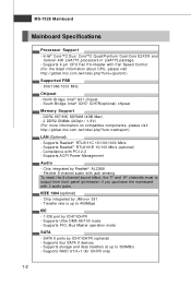
.../ICH7R (optional) - Supports four SATA II devices - Supports 4 pin CPU Fan Pin-Header with PCI 2.2 - SATA II ports by Realtek® ALC888 - Supports RAID 0/1/0+1 (for ICH7R only) 1-2 c om . Flexible 8-channel audio with 3 audio jacks. Supports storage and data transfers at up to output from front panel (pinheader) if you purchase the mainboard with jack sensing To reach the 8-channel sound effect, the 7th and 8th channels must to 400Mbps IDE - 1 IDE port by JMicron 381 - MS-7528 Mainboard Mainboard Specifications Processor Support - p hp...
.../ICH7R (optional) - Supports four SATA II devices - Supports 4 pin CPU Fan Pin-Header with PCI 2.2 - SATA II ports by Realtek® ALC888 - Supports RAID 0/1/0+1 (for ICH7R only) 1-2 c om . Flexible 8-channel audio with 3 audio jacks. Supports storage and data transfers at up to output from front panel (pinheader) if you purchase the mainboard with jack sensing To reach the 8-channel sound effect, the 7th and 8th channels must to 400Mbps IDE - 1 IDE port by JMicron 381 - MS-7528 Mainboard Mainboard Specifications Processor Support - p hp...
User Guide
Page 12
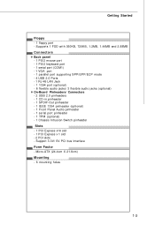
... PS/2 keyboard port - 1 serial port (COM1) - 1 VGA port - 1 parallel port supporting SPP/EPP/ECP mode - 4 USB 2.0 Ports - 1 RJ-45 LAN Jack - 1 1394 port (optional) - 6 flexible audio jacks/ 3 flexible audio jacks (optional) On-Board Pinheaders/ Connectors - 2 USB 2.0 pinheaders - 1 CD-in pinheader - 1 SPDIF-Out pinheader - 1 IEEE 1394 pinheader (optional) - 1 Front Panel Audio pinheader - 1 serial port pinheader - 1 TPM (optional) - 1 Chassis Intrusion Switch pinheader Slots - 1 PCI Express x16 slot - 1 PCI Express x 1 slot - 2 PCI slots - Getting Started Floppy - 1 floppy port - Micro-ATX...
... PS/2 keyboard port - 1 serial port (COM1) - 1 VGA port - 1 parallel port supporting SPP/EPP/ECP mode - 4 USB 2.0 Ports - 1 RJ-45 LAN Jack - 1 1394 port (optional) - 6 flexible audio jacks/ 3 flexible audio jacks (optional) On-Board Pinheaders/ Connectors - 2 USB 2.0 pinheaders - 1 CD-in pinheader - 1 SPDIF-Out pinheader - 1 IEEE 1394 pinheader (optional) - 1 Front Panel Audio pinheader - 1 serial port pinheader - 1 TPM (optional) - 1 Chassis Intrusion Switch pinheader Slots - 1 PCI Express x16 slot - 1 PCI Express x 1 slot - 2 PCI slots - Getting Started Floppy - 1 floppy port - Micro-ATX...
User Guide
Page 23
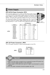
... and the pins are connected to proper ATX power supplies to the CPU. Power supply of the mainboard. 2. If you'd like . You may use the 20-pin ATX power supply as you to connect an ATX 24-pin power supply. Make sure that all the connectors are aligned. Then push down the power supply firmly into the connector. Hardware Setup Power Supply ATX 24-Pin Power Connector: ATX1 This connector allows you like to use the 20-pin ATX power supply, please plug your power supply along with pin 1 & pin 13...
... and the pins are connected to proper ATX power supplies to the CPU. Power supply of the mainboard. 2. If you'd like . You may use the 20-pin ATX power supply as you to connect an ATX 24-pin power supply. Make sure that all the connectors are aligned. Then push down the power supply firmly into the connector. Hardware Setup Power Supply ATX 24-Pin Power Connector: ATX1 This connector allows you like to use the 20-pin ATX power supply, please plug your power supply along with pin 1 & pin 13...
User Guide
Page 26
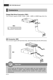
Refer to master / slave mode by the vendors for jumper setting instructions. 2-12 IDE1 Important If you install two IDE devices on the same cable, you must configure the drives separately to IDE device's documentation supplied by setting jumpers. FDD1 IDE Connector: IDE1 This connector supports IDE hard disk drives, optical disk drives and other IDE devices. MS-7528 Mainboard Connectors Floppy Disk Drive Connector: FDD1 This connector supports 360KB, 720KB, 1.2MB, 1.44MB or 2.88MB floppy disk drive.
Refer to master / slave mode by the vendors for jumper setting instructions. 2-12 IDE1 Important If you install two IDE devices on the same cable, you must configure the drives separately to IDE device's documentation supplied by setting jumpers. FDD1 IDE Connector: IDE1 This connector supports IDE hard disk drives, optical disk drives and other IDE devices. MS-7528 Mainboard Connectors Floppy Disk Drive Connector: FDD1 This connector supports 360KB, 720KB, 1.2MB, 1.44MB or 2.88MB floppy disk drive.
User Guide
Page 28
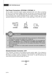
... SE NS OR SYSFAN2 Important 1. Fan cooler set with +12V. If the mainboard has a System Hardware Monitor chipset on the screen. Chassis Intrusion Connector: JCI1 This connector connects to take advantage of BIOS and install Dual Core Center utility that the red wire is opened, the chassis intrusion mechanism will record this status and show a warning message on -board, you must use a specially designed fan with speed sensor to the chassis intrusion switch cable.
... SE NS OR SYSFAN2 Important 1. Fan cooler set with +12V. If the mainboard has a System Hardware Monitor chipset on the screen. Chassis Intrusion Connector: JCI1 This connector connects to take advantage of BIOS and install Dual Core Center utility that the red wire is opened, the chassis intrusion mechanism will record this status and show a warning message on -board, you must use a specially designed fan with speed sensor to the chassis intrusion switch cable.
User Guide
Page 33
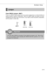
W ith the CMOS RAM, the system can clear CMOS by shorting 2-3 pin while the system is turned on ; Then return to keep the data of system configuration. If you want to clear the system configuration, set the jumper to clear data. 1 1 1 JBAT1 3 Keep Data 3 Clear Data Important You can automatically boot OS every time it will damage the mainboard. 2-19 Avoid clearing the CMOS while the system is a CMOS RAM onboard that has a power supply from an external battery to 1-2 pin position. it is off. Hardware Setup Jumper Clear CMOS Jumper: JBAT1 There is on .
W ith the CMOS RAM, the system can clear CMOS by shorting 2-3 pin while the system is turned on ; Then return to keep the data of system configuration. If you want to clear the system configuration, set the jumper to clear data. 1 1 1 JBAT1 3 Keep Data 3 Clear Data Important You can automatically boot OS every time it will damage the mainboard. 2-19 Avoid clearing the CMOS while the system is a CMOS RAM onboard that has a power supply from an external battery to 1-2 pin position. it is off. Hardware Setup Jumper Clear CMOS Jumper: JBAT1 There is on .
User Guide
Page 34
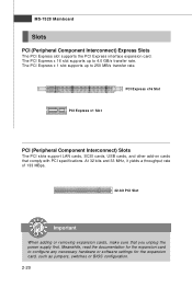
... removing expansion cards, make sure that comply with PCI specifications. Meanwhile, read the documentation for the expansion card, such as jumpers, switches or BIOS configuration. 2-20 The PCI Express x 1 slot supports up to 4.0 GB/s transfer rate. PCI Express x1 Slot PCI Express x16 Slot PCI (Peripheral Component Interconnect) Slots The PCI slots support LAN cards, SCSI cards, USB cards, and other add-on cards that you unplug the power supply first. The PCI Express x 16 slot supports up to configure any necessary hardware or software settings for the expansion card...
... removing expansion cards, make sure that comply with PCI specifications. Meanwhile, read the documentation for the expansion card, such as jumpers, switches or BIOS configuration. 2-20 The PCI Express x 1 slot supports up to 4.0 GB/s transfer rate. PCI Express x1 Slot PCI Express x16 Slot PCI (Peripheral Component Interconnect) Slots The PCI slots support LAN cards, SCSI cards, USB cards, and other add-on cards that you unplug the power supply first. The PCI Express x 16 slot supports up to configure any necessary hardware or software settings for the expansion card...
User Guide
Page 42
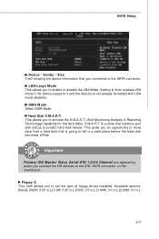
... DMA Mode. Setting to Auto enables LBA mode if the device supports it and the devices is a utility that monitors your disk status to the IDE/ SATA connector on the mainboard. Hard Disk S.M.A.R.T. Floppy A This item allows you connect the HD devices to predict hard disk failure. IImmppoorrttaanntt Primary IDE M aster/ Slave, Serial-ATA 1/2/3/4 Channel are appearing when you to the SATA connector. This gives you an opportunity to move data from a hard disk that you connected to set the type of floppy drives installed. This...
... DMA Mode. Setting to Auto enables LBA mode if the device supports it and the devices is a utility that monitors your disk status to the IDE/ SATA connector on the mainboard. Hard Disk S.M.A.R.T. Floppy A This item allows you connect the HD devices to predict hard disk failure. IImmppoorrttaanntt Primary IDE M aster/ Slave, Serial-ATA 1/2/3/4 Channel are appearing when you to the SATA connector. This gives you an opportunity to move data from a hard disk that you connected to set the type of floppy drives installed. This...
User Guide
Page 44
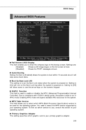
... of your operating system. Advanced BIOS Features BIOS Setup Full Screen LOGO Display This item enables you to select which MPS (Multi-Processor Specification) version to be used to enable or disable the APIC (Advanced Programmable Interrupt Controller). Primary Graphics Adapter This setting specifies which version to use the arrow keys on the full screen at boot. [Disabled] Shows the POST messages at boot. To find out which graphic card is able to [On] will...
... of your operating system. Advanced BIOS Features BIOS Setup Full Screen LOGO Display This item enables you to select which MPS (Multi-Processor Specification) version to be used to enable or disable the APIC (Advanced Programmable Interrupt Controller). Primary Graphics Adapter This setting specifies which version to use the arrow keys on the full screen at boot. [Disabled] Shows the POST messages at boot. To find out which graphic card is able to [On] will...
User Guide
Page 45
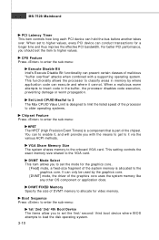
... video memory. MS-7528 Mainboard PCI Latency Timer This item controls how long each PCI device can to enable it, and will provide you to set to the graphics core. VGA Share Memory Size The system shares memory to it cannot. W hen set the mode for the graphics core.. [Fixed] mode, a fixed-size fragment of the system memory is designed to limit the listed speed of the processor to older operating systems. Chipset Feature Press to load the disk...
... video memory. MS-7528 Mainboard PCI Latency Timer This item controls how long each PCI device can to enable it, and will provide you to set to the graphics core. VGA Share Memory Size The system shares memory to it cannot. W hen set the mode for the graphics core.. [Fixed] mode, a fixed-size fragment of the system memory is designed to limit the listed speed of the processor to older operating systems. Chipset Feature Press to load the disk...
User Guide
Page 46
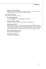
... Press to enter the sub-menu: TCG/TPM SUPPORT This setting allows you to enable or disable the TPM security chip. TPM Owner Status This item is not configurable. W hen you press , a warning message will appear to ask if you to clear the user information saved in the security chip. TPM Enable/Disable Status This item is not configurable. 3-11 BIOS Setup Boot From Other Device Setting the option to...
... Press to enter the sub-menu: TCG/TPM SUPPORT This setting allows you to enable or disable the TPM security chip. TPM Owner Status This item is not configurable. W hen you press , a warning message will appear to ask if you to clear the user information saved in the security chip. TPM Enable/Disable Status This item is not configurable. 3-11 BIOS Setup Boot From Other Device Setting the option to...
User Guide
Page 47
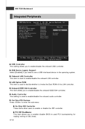
... you to enable/ disable BIOS to used to decide whether to invoke the Boot ROM of the LAN controller. Audio Controller This setting is used to enable/disable the onboard LAN controller. PCI IDE BusMaster This item allows you to enable/disable the onboard IEEE1394 controller. Onboard LAN Controller This item is used PCI busmastering for reading/ writing to IDE drives. 3-12 LAN Option ROM This item is used to enable/disable the onboard audio controller. USB Device Legacy Support Select [Enabled] if you to enable/disable the onboard USB controller. MS-7528 Mainboard Integrated...
... you to enable/ disable BIOS to used to decide whether to invoke the Boot ROM of the LAN controller. Audio Controller This setting is used to enable/disable the onboard LAN controller. PCI IDE BusMaster This item allows you to enable/disable the onboard IEEE1394 controller. Onboard LAN Controller This item is used PCI busmastering for reading/ writing to IDE drives. 3-12 LAN Option ROM This item is used to enable/disable the onboard audio controller. USB Device Legacy Support Select [Enabled] if you to enable/disable the onboard USB controller. MS-7528 Mainboard Integrated...

User Guide
Page 50
... be awakened from what power saving modes when input signal of the USB device to wake up the system on PCIE device. BIOS Setup Power Button Function This feature sets the function of the PS/2 keyboard is used to RAM) sleep state. Settings are : [On/ Off] The power button functions as normal power off button. [Suspend] W hen you press the power button, the computer enters the suspend/sleep mode, but if the button is pressed for more...
... be awakened from what power saving modes when input signal of the USB device to wake up the system on PCIE device. BIOS Setup Power Button Function This feature sets the function of the PS/2 keyboard is used to RAM) sleep state. Settings are : [On/ Off] The power button functions as normal power off button. [Suspend] W hen you press the power button, the computer enters the suspend/sleep mode, but if the button is pressed for more...

User Guide
Page 51
... can control the CPU fan speed automatically depending on the current temperature to keep it with in a specific range. The setting of the field will automatically return to the target value, the smart fan function will be activated. MS-7528 Mainboard H/W Monitor Chassis Intrusion The field enables or disables the feature of the monitored hardware devices/ components such as CPU voltage, temperatures and all fans' speeds. 3-16 CPU Smart FAN Target The mainboard provides the Smart Fan...
... can control the CPU fan speed automatically depending on the current temperature to keep it with in a specific range. The setting of the field will automatically return to the target value, the smart fan function will be activated. MS-7528 Mainboard H/W Monitor Chassis Intrusion The field enables or disables the feature of the monitored hardware devices/ components such as CPU voltage, temperatures and all fans' speeds. 3-16 CPU Smart FAN Target The mainboard provides the Smart Fan...
User Guide
Page 54
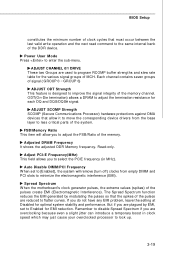
... Power User M ode Press to Enabled for each DQ and DQS/DQS# signal. FSB/Memory Ratio This item will remove (turn off) clocks from the base layer to the same internal bank of the DDR device. Adjusted DRAM Frequency It shows the adjusted DDR Memory frequency. Spread Spectrum W hen the motherboard's clock generator pulses, the extreme values (spikes) of MCH. Auto Disable DIMM/PCI Frequency W hen set to enter the sub-menu...
... Power User M ode Press to Enabled for each DQ and DQS/DQS# signal. FSB/Memory Ratio This item will remove (turn off) clocks from the base layer to the same internal bank of the DDR device. Adjusted DRAM Frequency It shows the adjusted DDR Memory frequency. Spread Spectrum W hen the motherboard's clock generator pulses, the extreme values (spikes) of MCH. Auto Disable DIMM/PCI Frequency W hen set to enter the sub-menu...
User Guide
Page 60
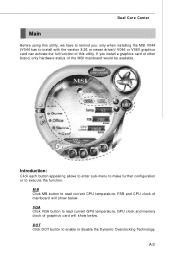
... disable the Dynamic Overclocking Technology. MB Click MB button to read current GPU temperature, GPU clock and memory clock of this utility, we have to remind you install a graphics card of other brand, only hardware status of mainboard will show below . If you : only when installing the MSI V044 (V044 has to read current CPU temperature, FSB and CPU clock of the MSI mainboard would be available. A-3 VGA Click VGA button to install with the version...
... disable the Dynamic Overclocking Technology. MB Click MB button to read current GPU temperature, GPU clock and memory clock of this utility, we have to remind you install a graphics card of other brand, only hardware status of mainboard will show below . If you : only when installing the MSI V044 (V044 has to read current CPU temperature, FSB and CPU clock of the MSI mainboard would be available. A-3 VGA Click VGA button to install with the version...
User Guide
Page 71
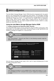
... provides BIOS and DOS disk services. Using the Intel Matrix Stroage Manager Option ROM 1. During the Power-On Self Test (POST), the following message will appear for Serial ATA" status screen, which should appear early in system boot-up, during the POST (Power-On Self Test). B-3 After the above message shows, press and keys simultaneously to enter the RAID Configuration Utility. Creating, Deleting and Resetting RAID Volumes: The Serial ATA RAID volume...
... provides BIOS and DOS disk services. Using the Intel Matrix Stroage Manager Option ROM 1. During the Power-On Self Test (POST), the following message will appear for Serial ATA" status screen, which should appear early in system boot-up, during the POST (Power-On Self Test). B-3 After the above message shows, press and keys simultaneously to enter the RAID Configuration Utility. Creating, Deleting and Resetting RAID Volumes: The Serial ATA RAID volume...
User Guide
Page 77
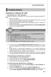
... the CD-ROM drive. 2. Insert the MSI CD into the CD-ROM drive. 2. Choose the driver Intel(R) 82801GR SATA RAID Controller from the dropdown list that appears on the Setup screen. 3. Setup will appear. 3. Press to continue with installation. 6. Click the "Browse CD" on W indows XP Setup screen, and press the key. 5. The CD will auto-run and the setup screen will now load all devices are specified, press to a formatted floppy disk. 4. B-9 Press...
... the CD-ROM drive. 2. Insert the MSI CD into the CD-ROM drive. 2. Choose the driver Intel(R) 82801GR SATA RAID Controller from the dropdown list that appears on the Setup screen. 3. Setup will appear. 3. Press to continue with installation. 6. Click the "Browse CD" on W indows XP Setup screen, and press the key. 5. The CD will auto-run and the setup screen will now load all devices are specified, press to a formatted floppy disk. 4. B-9 Press...


