User Guide
Page 8
...Connectors ...2-11 Switc h ...2-18 Button ...2-19 Slots ...2-20 Chapter 3 BIOS Setup 3-1 Entering Setup ...3-2 The Main Menu ...3-4 Standard CMOS Features 3-6 Advanced BIOS Features 3-9 Integrated Peripherals 3-12 Power Management Setup 3-14 H/W Monitor ...3-17 BIOS Setting Password 3-18 Cell Menu ...3-19 ...Safe/ Optimized Defaults 3-26 Appendix A Realtek Audio A-1 Installing the Realtek HD Audio Driver A-2 Software Configuration A-4 Hardware Setup A-19 viii CONTENTS Copyright Notice ...ii Trademarks ...ii Revision History ...ii Technical Support ...ii Safety Instructions ...iii FCC...
...Connectors ...2-11 Switc h ...2-18 Button ...2-19 Slots ...2-20 Chapter 3 BIOS Setup 3-1 Entering Setup ...3-2 The Main Menu ...3-4 Standard CMOS Features 3-6 Advanced BIOS Features 3-9 Integrated Peripherals 3-12 Power Management Setup 3-14 H/W Monitor ...3-17 BIOS Setting Password 3-18 Cell Menu ...3-19 ...Safe/ Optimized Defaults 3-26 Appendix A Realtek Audio A-1 Installing the Realtek HD Audio Driver A-2 Software Configuration A-4 Hardware Setup A-19 viii CONTENTS Copyright Notice ...ii Trademarks ...ii Revision History ...ii Technical Support ...ii Safety Instructions ...iii FCC...

User Guide
Page 15
Use a grounded wrist strap before handling computer components. Hardware Setup Chapter 2 Hardware Setup This chapter provides you install in holding the components and follow the installation procedures. For some components, if you with the information about hardware setup procedures. Static electricity may damage the components. 2-1 While doing the installation, be careful in the wrong orientation, the components will not work properly.
Use a grounded wrist strap before handling computer components. Hardware Setup Chapter 2 Hardware Setup This chapter provides you install in holding the components and follow the installation procedures. For some components, if you with the information about hardware setup procedures. Static electricity may damage the components. 2-1 While doing the installation, be careful in the wrong orientation, the components will not work properly.
User Guide
Page 17
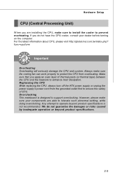
... caused by inadequate operation or beyond product specifications is designed to enhance heat dissipation. Always make sure your dealer before turning on the computer. Hardware Setup CPU (Central Processing Unit) W hen you are able to ensure the safety of thermal paste (or thermal tape) between the CPU and the heatsink to...
... caused by inadequate operation or beyond product specifications is designed to enhance heat dissipation. Always make sure your dealer before turning on the computer. Hardware Setup CPU (Central Processing Unit) W hen you are able to ensure the safety of thermal paste (or thermal tape) between the CPU and the heatsink to...
User Guide
Page 19
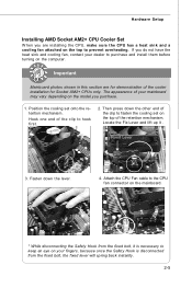
... fingers, because once the Safety Hook is disconnected from the fixed bolt, it . Position the cooling set on the top of the retention mechanism. Hardware Setup Installing AMD Socket AM2+ CPU Cooler Set W hen you are for demonstration of the cooler installation for Socket AM2+ CPUs only. Then press down the...
... fingers, because once the Safety Hook is disconnected from the fixed bolt, it . Position the cooling set on the top of the retention mechanism. Hardware Setup Installing AMD Socket AM2+ CPU Cooler Set W hen you are for demonstration of the cooler installation for Socket AM2+ CPUs only. Then press down the...

User Guide
Page 21
... is properly inserted in place by the DIMM slot clips at each side of the same type and density in the DDR2 DIMM slots. - Hardware Setup Installing Memory Modules 1.
... is properly inserted in place by the DIMM slot clips at each side of the same type and density in the DDR2 DIMM slots. - Hardware Setup Installing Memory Modules 1.
User Guide
Page 23
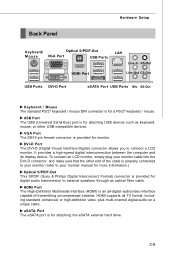
... USB-compatible devices. HDMI Port The High-Definition Multimedia Interface (HDMI) is properly connected to your monitor (refer to connect a LCD monitor. Back Panel Hardware Setup Keyboard/ Optical S/PDIF-Out Mouse VGA Port USB Ports LAN Line-In RS-Out HDMI Port Line-Out CS-Out USB Ports DVI-D Port eSATA...
... USB-compatible devices. HDMI Port The High-Definition Multimedia Interface (HDMI) is properly connected to your monitor (refer to connect a LCD monitor. Back Panel Hardware Setup Keyboard/ Optical S/PDIF-Out Mouse VGA Port USB Ports LAN Line-In RS-Out HDMI Port Line-Out CS-Out USB Ports DVI-D Port eSATA...
User Guide
Page 25
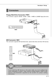
Refer to master / slave mode by the vendors for jumper setting instructions. 2-11 IDE1 Important If you install two IDE devices on the same cable, you must configure the drives separately to IDE device's documentation supplied by setting jumpers. Hardware Setup Connectors Floppy Disk Drive Connector: FDD1 This connector supports 360KB, 720KB, 1.2MB, 1.44MB or 2.88MB floppy disk drive. FDD1 IDE Connector: IDE1 This connector supports IDE hard disk drives, optical disk drives and other IDE devices.
Refer to master / slave mode by the vendors for jumper setting instructions. 2-11 IDE1 Important If you install two IDE devices on the same cable, you must configure the drives separately to IDE device's documentation supplied by setting jumpers. Hardware Setup Connectors Floppy Disk Drive Connector: FDD1 This connector supports 360KB, 720KB, 1.2MB, 1.44MB or 2.88MB floppy disk drive. FDD1 IDE Connector: IDE1 This connector supports IDE hard disk drives, optical disk drives and other IDE devices.

User Guide
Page 27
... NC CPU_FAN1 SE NS OR +1 2V GND SYS_FAN1 SYS_FAN2 Important 1. To clear the warning, you must enter the BIOS utility and clear the record. Hardware Setup Fan Power Connectors: CPU_FAN1, SYS_FAN1/2 The fan power connectors support system cooling fan with 3 or 4 pins power connector are both available for proper CPU cooling...
... NC CPU_FAN1 SE NS OR +1 2V GND SYS_FAN1 SYS_FAN2 Important 1. To clear the warning, you must enter the BIOS utility and clear the record. Hardware Setup Fan Power Connectors: CPU_FAN1, SYS_FAN1/2 The fan power connectors support system cooling fan with 3 or 4 pins power connector are both available for proper CPU cooling...

User Guide
Page 29
... panel microphone JACK1 Jack detection sense line from front panel JACK2 CD-In Connector: JCD1 This connector is connected Analog Port - JCD1 R GND L 2-15 Hardware Setup Front Panel Audio Connector: JAUD1 This connector allows you to connect the front panel audio and is connected to the analog header.
... panel microphone JACK1 Jack detection sense line from front panel JACK2 CD-In Connector: JCD1 This connector is connected Analog Port - JCD1 R GND L 2-15 Hardware Setup Front Panel Audio Connector: JAUD1 This connector allows you to connect the front panel audio and is connected to the analog header.

User Guide
Page 31
JUSB1~3 2 10 1 9 Pin Definition PIN SIGNAL 1 VCC 3 USB0- 5 USB0+ 7 GND 9 Key (no pin) PIN SIGNAL 2 VCC 4 USB1- 6 USB1+ 8 GND 10 USBOC USB 2.0 Bracket (Optional) Important Note that the pins of VCC and GND must be connected correctly to avoid possible damage. 2-17 Hardware Setup Front USB Connector: JUSB1 ~ 3 These connectors, compliant with Intel® I/O Connectivity Design Guide, is ideal for connecting high-speed USB interface peripherals such as USB HDD, digital cameras, MP3 players, printers, modems and the like.
JUSB1~3 2 10 1 9 Pin Definition PIN SIGNAL 1 VCC 3 USB0- 5 USB0+ 7 GND 9 Key (no pin) PIN SIGNAL 2 VCC 4 USB1- 6 USB1+ 8 GND 10 USBOC USB 2.0 Bracket (Optional) Important Note that the pins of VCC and GND must be connected correctly to avoid possible damage. 2-17 Hardware Setup Front USB Connector: JUSB1 ~ 3 These connectors, compliant with Intel® I/O Connectivity Design Guide, is ideal for connecting high-speed USB interface peripherals such as USB HDD, digital cameras, MP3 players, printers, modems and the like.

User Guide
Page 33
... section will explain how to change your motherboard's function through the use the button to clear data. Press the button to clear the data. Hardware Setup Button The motherboard provides the following button for you want to clear the system configuration, use of button.
... section will explain how to change your motherboard's function through the use the button to clear data. Press the button to clear the data. Hardware Setup Button The motherboard provides the following button for you want to clear the system configuration, use of button.

User Guide
Page 35
... PCI IRQ pins are hardware lines over which devices can send interrupt signals to the PCI bus pins as jumpers, switches or BIOS configuration. Hardware Setup PCI (Peripheral Component Interconnect) Slot The PCI slot supports LAN card, SCSI card, USB card, and other add-on cards that comply with PCI specifications...
... PCI IRQ pins are hardware lines over which devices can send interrupt signals to the PCI bus pins as jumpers, switches or BIOS configuration. Hardware Setup PCI (Peripheral Component Interconnect) Slot The PCI slot supports LAN card, SCSI card, USB card, and other add-on cards that comply with PCI specifications...

User Guide
Page 37
...; Control Center: Select the Advanced View from the manufacturer. 2-23 The following aspect appears in the Catalyst™ Control Center that needs to operate. Hardware Setup 3.W hen all of the hardware and software has been properly set up and installed, reboot the system. for CrossFire™ to be enabled for more...
...; Control Center: Select the Advanced View from the manufacturer. 2-23 The following aspect appears in the Catalyst™ Control Center that needs to operate. Hardware Setup 3.W hen all of the hardware and software has been properly set up and installed, reboot the system. for CrossFire™ to be enabled for more...

User Guide
Page 38
You may need to run the Setup program when: ² An error message appears on the BIOS Setup program and allows you to run SETUP. ² You want to configure the system for customized features. 3-1 Chapter 3 BIOS Setup BIOS Setup This chapter provides information on the screen during the system booting up, and requests you to change the default settings for optimum use.
You may need to run the Setup program when: ² An error message appears on the BIOS Setup program and allows you to run SETUP. ² You want to configure the system for customized features. 3-1 Chapter 3 BIOS Setup BIOS Setup This chapter provides information on the screen during the system booting up, and requests you to change the default settings for optimum use.
User Guide
Page 39
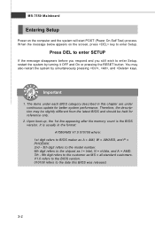
...V1.0 refers to the BIOS version. 010108 refers to the date this chapter are under continuous update for reference only. 2. Press DEL to enter SETUP If the message disappears before you respond and you still wish to the customer as MS = all standard customers. You may be slightly different from ... description may also restart the system by turning it OFF and On or pressing the RESET button. MS-7550 Mainboard Entering Setup Power on the screen, press key to enter Setup. Upon boot-up, the 1st line appearing after the memory count is usually in this BIOS was released. 3-2 W hen the ...
...V1.0 refers to the BIOS version. 010108 refers to the date this chapter are under continuous update for reference only. 2. Press DEL to enter SETUP If the message disappears before you respond and you still wish to the customer as MS = all standard customers. You may be slightly different from ... description may also restart the system by turning it OFF and On or pressing the RESET button. MS-7550 Mainboard Entering Setup Power on the screen, press key to enter Setup. Upon boot-up, the 1st line appearing after the memory count is usually in this BIOS was released. 3-2 W hen the ...

User Guide
Page 40
... select the item. Sub-M enu If you can be launched from this screen from field to call up the sub-menu. General Help The BIOS setup program provides a General Help screen. The on-line description of certain fields that means a sub-menu can make changes Memory-Z Load Optimized Defaults Load ...Fail-Safe Defaults Save all the CMOS changes and exit Getting Help After entering the Setup menu, the first menu you will see is displayed at the bottom of the screen. You can use arrow keys ( ↑↓ ) to highlight ...
... select the item. Sub-M enu If you can be launched from this screen from field to call up the sub-menu. General Help The BIOS setup program provides a General Help screen. The on-line description of certain fields that means a sub-menu can make changes Memory-Z Load Optimized Defaults Load ...Fail-Safe Defaults Save all the CMOS changes and exit Getting Help After entering the Setup menu, the first menu you will see is displayed at the bottom of the screen. You can use arrow keys ( ↑↓ ) to highlight ...

User Guide
Page 41
... time, date etc. Integrated Peripherals Use this menu to specify your settings for power management. Power Management Setup Use this menu to specify your PC health status. Cell Menu Use this menu to setup the items of AMI® special enhanced features. MS-7550 Mainboard The Main Menu Standard CMOS Features Use...
... time, date etc. Integrated Peripherals Use this menu to specify your settings for power management. Power Management Setup Use this menu to specify your PC health status. Cell Menu Use this menu to setup the items of AMI® special enhanced features. MS-7550 Mainboard The Main Menu Standard CMOS Features Use...

User Guide
Page 42
Load Optimized Defaults Use this menu to CMOS and exit setup. Save & Exit Setup Save changes to load the default values set by the mainboard manufacturer specifically for optimal performance of the mainboard. BIOS Setup User Settings Use this menu to save/ load your settings to load the default values set by the BIOS vendor for stable system performance. Load Fail-Safe Defaults Use this menu to / from CMOS for BIOS. Exit Without Saving Abandon all changes and exit setup. 3-5
Load Optimized Defaults Use this menu to CMOS and exit setup. Save & Exit Setup Save changes to load the default values set by the mainboard manufacturer specifically for optimal performance of the mainboard. BIOS Setup User Settings Use this menu to save/ load your settings to load the default values set by the BIOS vendor for stable system performance. Load Fail-Safe Defaults Use this menu to / from CMOS for BIOS. Exit Without Saving Abandon all changes and exit setup. 3-5

User Guide
Page 43
... adjusted by numeric function keys. The time format is . MS-7550 Mainboard Standard CMOS Features The items in Standard CMOS Features Menu includes some basic setup items. Use the arrow keys to highlight the item and then use the or keys to select the value you want (usually the current date...
... adjusted by numeric function keys. The time format is . MS-7550 Mainboard Standard CMOS Features The items in Standard CMOS Features Menu includes some basic setup items. Use the arrow keys to highlight the item and then use the or keys to select the value you want (usually the current date...

User Guide
Page 44
... & E-SATA1 are appearing when you to set the type of floppy drives installed. 3-7 S.M.A.R.T is a utility that is not already formatted with LBA mode disabled. BIOS Setup Device / Vender / Size It will showing the device information that you an opportunity to move data from a hard disk that monitors your disk status to...
... & E-SATA1 are appearing when you to set the type of floppy drives installed. 3-7 S.M.A.R.T is a utility that is not already formatted with LBA mode disabled. BIOS Setup Device / Vender / Size It will showing the device information that you an opportunity to move data from a hard disk that monitors your disk status to...

