User Guide
Page 4
.... com.tw/program/service/faq/faq/esc_faq_list.php h Contact our technical staff at: support@msi.com.tw Safety Instructions 1. Always read the safety instructions carefully. 2. Always Unplug the Power Cord before setting it work well or you can not get the equipment checked by the manufacturer. Keep this User's Manual for technical guide, BIOS updates, driver updates, and other information: http://www.msi.com.tw & http...
.... com.tw/program/service/faq/faq/esc_faq_list.php h Contact our technical staff at: support@msi.com.tw Safety Instructions 1. Always read the safety instructions carefully. 2. Always Unplug the Power Cord before setting it work well or you can not get the equipment checked by the manufacturer. Keep this User's Manual for technical guide, BIOS updates, driver updates, and other information: http://www.msi.com.tw & http...
User Guide
Page 5
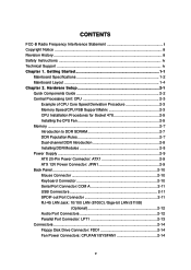
... CPU Fan 2-5 Memory ...2-7 Introduction to DDR SDRAM 2-7 DDR Population Rules 2-7 Dual-channel DDR Introduction 2-8 Installing DDR Modules 2-8 Power Supply ...2-9 ATX 20-Pin Power Connector: ATX1 2-9 ATX 12V Power Connector: JPW1 2-9 Back Panel ...2-10 Mouse Connector 2-10 Keyboard Connector 2-10 Serial Port Connector: COM A 2-11 USB Connectors 2-11 SPDIF-out Port Connector 2-11 RJ-45 LAN Jack: 10/100 LAN (8100C) /Giga-bit LAN (8110S) (Optional 2-12 Audio Port Connectors 2-12 Parallel Port Connector: LPT1 2-13 Connectors ...2-14 Floppy Disk Drive Connector: FDD1 2-14 Fan Power...
... CPU Fan 2-5 Memory ...2-7 Introduction to DDR SDRAM 2-7 DDR Population Rules 2-7 Dual-channel DDR Introduction 2-8 Installing DDR Modules 2-8 Power Supply ...2-9 ATX 20-Pin Power Connector: ATX1 2-9 ATX 12V Power Connector: JPW1 2-9 Back Panel ...2-10 Mouse Connector 2-10 Keyboard Connector 2-10 Serial Port Connector: COM A 2-11 USB Connectors 2-11 SPDIF-out Port Connector 2-11 RJ-45 LAN Jack: 10/100 LAN (8100C) /Giga-bit LAN (8110S) (Optional 2-12 Audio Port Connectors 2-12 Parallel Port Connector: LPT1 2-13 Connectors ...2-14 Floppy Disk Drive Connector: FDD1 2-14 Fan Power...

User Guide
Page 6
... Status 3-23 Frequency/Voltage Control 3-24 Set Supervisor/User Password 3-27 Load High Performance/BIOS Setup Defaults 3-28 vi CD-In Connector: CD1 2-14 ATA100 Hard Disk Connectors: IDE1 & IDE2 2-15 Front USB Connectors: JUSB2 & JUSB3 2-15 Serial ATA HDD Connectors: SATA1, SATA2 2-16 S-Bracket (SPDIF) Connector: JSP1 (Optional 2-17 Front Panel Connectors: JFP1 & JFP2 2-18 Front Panel Audio Connector: JAUD1 2-19 D-Bracket™ 2 Connector: JDB1 (Optional 2-20 Jumpers ...2-21 Clear CMOS Jumper: JBAT1 2-21 Slots ...2-22 AGP (Accelerated Graphics Port) Slot 2-22 PCI (Peripheral...
... Status 3-23 Frequency/Voltage Control 3-24 Set Supervisor/User Password 3-27 Load High Performance/BIOS Setup Defaults 3-28 vi CD-In Connector: CD1 2-14 ATA100 Hard Disk Connectors: IDE1 & IDE2 2-15 Front USB Connectors: JUSB2 & JUSB3 2-15 Serial ATA HDD Connectors: SATA1, SATA2 2-16 S-Bracket (SPDIF) Connector: JSP1 (Optional 2-17 Front Panel Connectors: JFP1 & JFP2 2-18 Front Panel Audio Connector: JAUD1 2-19 D-Bracket™ 2 Connector: JDB1 (Optional 2-20 Jumpers ...2-21 Clear CMOS Jumper: JBAT1 2-21 Slots ...2-22 AGP (Accelerated Graphics Port) Slot 2-22 PCI (Peripheral...
User Guide
Page 8
... / 848P chipset - MS-6788 ATX Mainboard Mainboard Specifications CPU h Supports Intel® P4 Northwood / Prescott (Socket 478) processors. h FSB 400MHz (for Northwood only) / 533MHz / 800MHz depending on DIMM 1.3). (For the updated supporting memory modules, please visit http://www.msi.com.tw/ program/products/mainboard/mbd/pro_mbd_trp_list.php.) Slots h One AGP slot supports 8x/4x. Supports AGP 8X/4X interface. - h Five 32-bit v2.3 Master PCI bus slots (supports 3.3v/5v PCI bus interface). Can connect up to 2 Serial...
... / 848P chipset - MS-6788 ATX Mainboard Mainboard Specifications CPU h Supports Intel® P4 Northwood / Prescott (Socket 478) processors. h FSB 400MHz (for Northwood only) / 533MHz / 800MHz depending on DIMM 1.3). (For the updated supporting memory modules, please visit http://www.msi.com.tw/ program/products/mainboard/mbd/pro_mbd_trp_list.php.) Slots h One AGP slot supports 8x/4x. Supports AGP 8X/4X interface. - h Five 32-bit v2.3 Master PCI bus slots (supports 3.3v/5v PCI bus interface). Can connect up to 2 Serial...
User Guide
Page 18
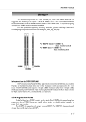
..., it supports both single-channel & dual-channel DDR. 2-7 You can install either single- For 848P Neo-V: DIMM1~2, max. It uses 2.5 volts as opposed to 3.3 volts used in SDR SDRAM, and requires 184-pin DIMM modules rather than 168-pin DIMM modules used by transferring data twice per cycle. DDR Population Rules Install at least one DIMM module on the DDR DIMM slots. Each DIMM slot supports up...
..., it supports both single-channel & dual-channel DDR. 2-7 You can install either single- For 848P Neo-V: DIMM1~2, max. It uses 2.5 volts as opposed to 3.3 volts used in SDR SDRAM, and requires 184-pin DIMM modules rather than 168-pin DIMM modules used by transferring data twice per cycle. DDR Population Rules Install at least one DIMM module on the DDR DIMM slots. Each DIMM slot supports up...

User Guide
Page 20
... GND GND GND -5V 5V 5V ATX 12V Power Connector: JPW1 This 12V power connector is inserted in the proper orientation and the pins are aligned. Power supply of the power supply is used to provide power to an ATX power supply. ATX 20-Pin Power Connector: ATX1 This connector allows you to connect to the CPU. 3 4 1 2 JPW1 JPW1 Pin Definition PIN SIGNAL 1 GND 2 GND 3 12V 4 12V MSI Reminds You... Hardware Setup Power Supply The mainboard supports ATX power supply for system stability. 2-9
... GND GND GND -5V 5V 5V ATX 12V Power Connector: JPW1 This 12V power connector is inserted in the proper orientation and the pins are aligned. Power supply of the power supply is used to provide power to an ATX power supply. ATX 20-Pin Power Connector: ATX1 This connector allows you to connect to the CPU. 3 4 1 2 JPW1 JPW1 Pin Definition PIN SIGNAL 1 GND 2 GND 3 12V 4 12V MSI Reminds You... Hardware Setup Power Supply The mainboard supports ATX power supply for system stability. 2-9
User Guide
Page 25
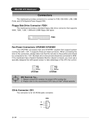
... of the CPU fan control. When connecting the wire to GND. It supports three-pin head connector. Floppy Disk Drive Connector: FDD1 The mainboard provides a standard floppy disk drive connector that the red wire is the positive and should be connected to take note that supports 360K, 720K, 1.2M, 1.44M and 2.88M floppy disk types. Please refer to FDD, IDE HDD, LAN, USB Ports, and CPU/System/Power Supply FAN. FDD1 Fan Power Connectors: CPUFAN1/SYSFAN1 The CPUFAN1 (processor fan) and SYSFAN1 (system fan) support system cooling fan with speed sensor...
... of the CPU fan control. When connecting the wire to GND. It supports three-pin head connector. Floppy Disk Drive Connector: FDD1 The mainboard provides a standard floppy disk drive connector that the red wire is the positive and should be connected to take note that supports 360K, 720K, 1.2M, 1.44M and 2.88M floppy disk types. Please refer to FDD, IDE HDD, LAN, USB Ports, and CPU/System/Power Supply FAN. FDD1 Fan Power Connectors: CPUFAN1/SYSFAN1 The CPUFAN1 (processor fan) and SYSFAN1 (system fan) support system cooling fan with speed sensor...
User Guide
Page 26
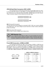
... four hard disk drives, CD-ROM, 120MB Floppy and other devices. IDE2 (Secondary IDE Connector) IDE2 can connect a Master and a Slave drive. Front USB Connectors: JUSB2 & JUSB3 The mainboard provides two USB 2.0 pin headers JUSB2 & JUSB3 that provides PIO mode 0~5, Bus Master, and Ultra DMA 33/66/100 function. You must configure the second drive to a maximum throughput of 480Mbps, which is 40 times faster than USB 1.1, and is ideal for jumper setting instructions. USB 2.0 technology...
... four hard disk drives, CD-ROM, 120MB Floppy and other devices. IDE2 (Secondary IDE Connector) IDE2 can connect a Master and a Slave drive. Front USB Connectors: JUSB2 & JUSB3 The mainboard provides two USB 2.0 pin headers JUSB2 & JUSB3 that provides PIO mode 0~5, Bus Master, and Ultra DMA 33/66/100 function. You must configure the second drive to a maximum throughput of 480Mbps, which is 40 times faster than USB 1.1, and is ideal for jumper setting instructions. USB 2.0 technology...

User Guide
Page 32
... is a CMOS RAM on board that has a power supply from external battery to keep the data of jumpers. Then return to clear the data: 1 JBAT1 1 1 3 Keep Data 3 Clear Data MSI Reminds You... Clear CMOS Jumper: JBAT1 There is turned on ; You can automatically boot OS every time it will explain how to change your motherboard's function through the use the JBAT1 (Clear CMOS Jumper ) to clear data. If you to set the computer...
... is a CMOS RAM on board that has a power supply from external battery to keep the data of jumpers. Then return to clear the data: 1 JBAT1 1 1 3 Keep Data 3 Clear Data MSI Reminds You... Clear CMOS Jumper: JBAT1 There is turned on ; You can automatically boot OS every time it will explain how to change your motherboard's function through the use the JBAT1 (Clear CMOS Jumper ) to clear data. If you to set the computer...
User Guide
Page 33
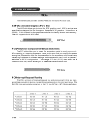
... 3D graphics. The orange PCI slot (PCI5) also works as jumpers, switches or BIOS configuration. When adding or removing expansion cards, make any necessary hardware or software settings for the graphics controller to insert the AGP graphics card. The PCI IRQ pins are hardware lines over which allows you to insert the expansion cards to insert the communcation card. It introduces a 66MHz, 32-bit channel for the expansion card, such as a communcation slot, which devices...
... 3D graphics. The orange PCI slot (PCI5) also works as jumpers, switches or BIOS configuration. When adding or removing expansion cards, make any necessary hardware or software settings for the graphics controller to insert the AGP graphics card. The PCI IRQ pins are hardware lines over which allows you to insert the expansion cards to insert the communcation card. It introduces a 66MHz, 32-bit channel for the expansion card, such as a communcation slot, which devices...
User Guide
Page 35
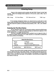
... Boot Device Floppy IDE-0 CDROM : 1st Floppy : IBM-DTLA-307038 : ATAPI CD-ROM DRIVE 40X M [Up/Dn] Select [RETURN] Boot [ESC] cancel The boot menu will still use the original first boot device to the settings in time. The selection will not make changes to boot up. 3-2 The system will start POST (Power On Self Test) process. Selecting the First Boot Device You are allowed to select the 1st boot device without entering the BIOS setup utility...
... Boot Device Floppy IDE-0 CDROM : 1st Floppy : IBM-DTLA-307038 : ATAPI CD-ROM DRIVE 40X M [Up/Dn] Select [RETURN] Boot [ESC] cancel The boot menu will still use the original first boot device to the settings in time. The selection will not make changes to boot up. 3-2 The system will start POST (Power On Self Test) process. Selecting the First Boot Device You are allowed to select the 1st boot device without entering the BIOS setup utility...
User Guide
Page 42
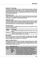
... to enable or disable the Intel Hyper Threading CPU function. BIOS Setup S.M.A.R.T. Setting options:[On], [Off]. When enabled, the BIOS will activate the floppy disk drives during the boot process: the drive activity light will increase the system performance. Enabling the functionality of the following platform Components: *CPU: An Intel® Pentium® 4 Processor with DRAM larger than 64MB. for the hard disks. Hyper Threading Function This field is a utility that supports HT Technology.
... to enable or disable the Intel Hyper Threading CPU function. BIOS Setup S.M.A.R.T. Setting options:[On], [Off]. When enabled, the BIOS will activate the floppy disk drives during the boot process: the drive activity light will increase the system performance. Enabling the functionality of the following platform Components: *CPU: An Intel® Pentium® 4 Processor with DRAM larger than 64MB. for the hard disks. Hyper Threading Function This field is a utility that supports HT Technology.
User Guide
Page 43
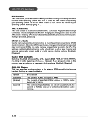
... ROM named in better system performance. Setting options: [Enabled], [Disabled]. MS-6788 ATX Mainboard MPS Revision This field allows you to select which version to use, consult the vendor of your operating system. To find out which MPS (Multi-Processor Specification) version to be written to and read from the main DRAM into cache memory, for the operating system. Due to compliance to PC2001 design guide...
... ROM named in better system performance. Setting options: [Enabled], [Disabled]. MS-6788 ATX Mainboard MPS Revision This field allows you to select which version to use, consult the vendor of your operating system. To find out which MPS (Multi-Processor Specification) version to be written to and read from the main DRAM into cache memory, for the operating system. Due to compliance to PC2001 design guide...
User Guide
Page 46
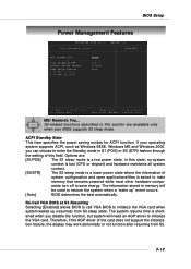
BIOS Setup Power Management Features MSI Reminds You... Options are available only when your operating system supports ACPI, such as Windows 98SE, Windows ME and Windows 2000, you disable the function, but system will be used to enter the Standby mode in S1 (POS) or S3 (STR) fashion through the setting of the card does not support the initialization feature, the display may work abnormally or not function after resuming...
BIOS Setup Power Management Features MSI Reminds You... Options are available only when your operating system supports ACPI, such as Windows 98SE, Windows ME and Windows 2000, you disable the function, but system will be used to enter the Standby mode in S1 (POS) or S3 (STR) fashion through the setting of the card does not support the initialization feature, the display may work abnormally or not function after resuming...
User Guide
Page 48
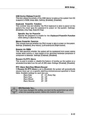
... MSI Reminds You... Settings: [Disabled], [Any Action], [Left-button] and [Right-button]. Settings: [Enabled], [Disabled]. Settings: [Enabled], [Disabled]. BIOS Setup USB Device Wakeup From S3 This item allows the activity of the USB device to wake up until it enters the operating system, before this setting, you must type the password to power on the system. Keyboard PowerOn Function This controls how and whether the PS/2 keyboard is able to [Specific Key]. Setting: [Enabled], [Disabled]. Available settings for the Keyboard PowerOn Function while setting...
... MSI Reminds You... Settings: [Disabled], [Any Action], [Left-button] and [Right-button]. Settings: [Enabled], [Disabled]. Settings: [Enabled], [Disabled]. BIOS Setup USB Device Wakeup From S3 This item allows the activity of the USB device to wake up until it enters the operating system, before this setting, you must type the password to power on the system. Keyboard PowerOn Function This controls how and whether the PS/2 keyboard is able to [Specific Key]. Setting: [Enabled], [Disabled]. Available settings for the Keyboard PowerOn Function while setting...
User Guide
Page 49
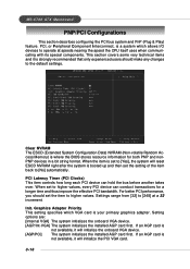
...-6788 ATX Mainboard PNP/PCI Configurations This section describes configuring the PCI bus system and PnP (Plug & Play) feature. When the item is set to [Yes], the system will reset ESCD NVRAM right after the system is booted up and then set the item to [248] at speeds nearing the speed the CPU itself uses when communicating with its special components. Setting options are: [Internal VGA] The system initializes the onboard VGA device...
...-6788 ATX Mainboard PNP/PCI Configurations This section describes configuring the PCI bus system and PnP (Plug & Play) feature. When the item is set to [Yes], the system will reset ESCD NVRAM right after the system is booted up and then set the item to [248] at speeds nearing the speed the CPU itself uses when communicating with its special components. Setting options are: [Internal VGA] The system initializes the onboard VGA device...
User Guide
Page 50
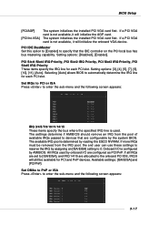
... . Setting options: [Disabled], [Enabled]. PCI Slot1/Slot4 IRQ Priority, PCI Slot2 IRQ Priority, PCI Slot3 IRQ Priority, PCI Slot5 IRQ Priority These items specify the IRQ line for each PCI slot. Set DMAs to PnP or ISA Press to devices that the IDE controller on the PCI local bus has bus mastering capability. If a PCI VGA card is used by onboard I /O is determined by the system BIOS. The system initializes the installed PCI VGA card first. Onboard I /O are configurable...
... . Setting options: [Disabled], [Enabled]. PCI Slot1/Slot4 IRQ Priority, PCI Slot2 IRQ Priority, PCI Slot3 IRQ Priority, PCI Slot5 IRQ Priority These items specify the IRQ line for each PCI slot. Set DMAs to PnP or ISA Press to devices that the IDE controller on the PCI local bus has bus mastering capability. If a PCI VGA card is used by onboard I /O is determined by the system BIOS. The system initializes the installed PCI VGA card first. Onboard I /O are configurable...
User Guide
Page 52
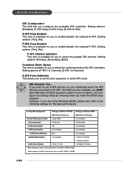
.... Setting options: [Legacy Mode], [Native Mode]. 3-19 USB Device Legacy Support Set to [Enabled] if your BIOS might be different depending on the motherboard you to determine how the RAID controller on your need to use any USB 1.1/2.0 device in the operating system that the options showed on the south bridge is used to SATA controller. [Legacy Mode] means you may use all the available IRQs. Setting options: [Disabled], [Enabled]. USB Controller This setting is going to switch to enable/disable the onboard USB controllers. On-Chip IDE Configuration Press to enter...
.... Setting options: [Legacy Mode], [Native Mode]. 3-19 USB Device Legacy Support Set to [Enabled] if your BIOS might be different depending on the motherboard you to determine how the RAID controller on your need to use any USB 1.1/2.0 device in the operating system that the options showed on the south bridge is used to SATA controller. [Legacy Mode] means you may use all the available IRQs. Setting options: [Disabled], [Enabled]. USB Controller This setting is going to switch to enable/disable the onboard USB controllers. On-Chip IDE Configuration Press to enter...
User Guide
Page 53
... configure the settings listed as following settings for you to set the boot sequence of serial ATA ports. When choosing P-ATA 1st Channel, you enter the BIOS setup program. MSI Reminds You... Setting options: [P-ATA 1st Channel], [S-ATA 1st Channel]. Setting options: [Disabled], [P-ATA Only], [S-ATA Only], [P-ATA+S-ATA]. P-ATA Channel Selection This item is available for you to the IDE1 and IDE2 are using Windows 98/Me, please also refer to enable/disable the onboard...
... configure the settings listed as following settings for you to set the boot sequence of serial ATA ports. When choosing P-ATA 1st Channel, you enter the BIOS setup program. MSI Reminds You... Setting options: [P-ATA 1st Channel], [S-ATA 1st Channel]. Setting options: [Disabled], [P-ATA Only], [S-ATA Only], [P-ATA+S-ATA]. P-ATA Channel Selection This item is available for you to the IDE1 and IDE2 are using Windows 98/Me, please also refer to enable/disable the onboard...
User Guide
Page 54
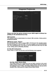
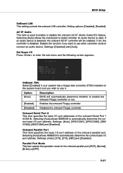
...port. Setting options: [Disabled], [Enabled]. Set Super I/O Press to enter the sub-menu and the following screen appears: OnBoard FDC Select [Enabled] if your system has a floppy disk controller (FDD) installed on the system board and you want to enable or disable the onboard AC'97 (Audio Codec'97) feature. if not, the controller is used to use it. Settings: [Auto], [3F8/COM1], [2F8/COM2], [3E8/ COM3], [2E8/COM4] and [Disabled]. Option [Auto] Description BIOS will be enabled; BIOS Setup OnBoard LAN This setting controls the onboard LAN controller. Onboard Serial...
...port. Setting options: [Disabled], [Enabled]. Set Super I/O Press to enter the sub-menu and the following screen appears: OnBoard FDC Select [Enabled] if your system has a floppy disk controller (FDD) installed on the system board and you want to enable or disable the onboard AC'97 (Audio Codec'97) feature. if not, the controller is used to use it. Settings: [Auto], [3F8/COM1], [2F8/COM2], [3E8/ COM3], [2E8/COM4] and [Disabled]. Option [Auto] Description BIOS will be enabled; BIOS Setup OnBoard LAN This setting controls the onboard LAN controller. Onboard Serial...

