Link-8 VHF Installation Manual EN
Page 2
... rights reserved. For free owner's manuals and the most current information on this product, its compliance. CAUTION CAUTION used to alert you to do so without prior written consent of Lowrance Electronics. Lowrance® is not responsible for any purpose, without notice. DANGER This is used without notice. Any unauthorized commercial distribution of this manual are simulated. It is...
... rights reserved. For free owner's manuals and the most current information on this product, its compliance. CAUTION CAUTION used to alert you to do so without prior written consent of Lowrance Electronics. Lowrance® is not responsible for any purpose, without notice. DANGER This is used without notice. Any unauthorized commercial distribution of this manual are simulated. It is...
Link-8 VHF Installation Manual EN
Page 3
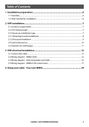
Link-8 Installation Instructions 3 NMEA 2000...15 3.3 Wiring diagram - NMEA 0183 connections 17 4 Setup your radio - Table of Contents 1 Installation preparation 6 1.1 Checklist...6 1.2 Tools needed for installation...6 2 VHF installation 7 2.1 Location requirements...7 2.2 LCD viewing angle...7 2.3 Choose an installation type...7 2.3.1 Mounting bracket installation...8 2.3.2 Recessed installation...9 2.4 Link-8 dimensions...10 2.5 Handset mic wall hanger...11 3 VHF electrical installation 12 3.1 Connect the radio...12 3.2 Wiring diagram - Your user MMSI 18 Lowrance - External ...
Link-8 Installation Instructions 3 NMEA 2000...15 3.3 Wiring diagram - NMEA 0183 connections 17 4 Setup your radio - Table of Contents 1 Installation preparation 6 1.1 Checklist...6 1.2 Tools needed for installation...6 2 VHF installation 7 2.1 Location requirements...7 2.2 LCD viewing angle...7 2.3 Choose an installation type...7 2.3.1 Mounting bracket installation...8 2.3.2 Recessed installation...9 2.4 Link-8 dimensions...10 2.5 Handset mic wall hanger...11 3 VHF electrical installation 12 3.1 Connect the radio...12 3.2 Wiring diagram - Your user MMSI 18 Lowrance - External ...
Link-8 VHF Installation Manual EN
Page 4
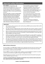
... Link-8 in order to use the instrument and transducers in a location that are unsure who to contact, consult your national radio communications authorities before applying this Lowrance VHF radio may be the official version of your Lowrance dealer. Lowrance recommends that you may need an individual operator's license. Link-8 Installation Instructions This manual represents the Link-8 as a safety device, this radio must obtain a user MMSI (Marine Mobile Service...
... Link-8 in order to use the instrument and transducers in a location that are unsure who to contact, consult your national radio communications authorities before applying this Lowrance VHF radio may be the official version of your Lowrance dealer. Lowrance recommends that you may need an individual operator's license. Link-8 Installation Instructions This manual represents the Link-8 as a safety device, this radio must obtain a user MMSI (Marine Mobile Service...
Link-8 VHF Installation Manual EN
Page 5
... antenna. However, there is subject to comply with CE under model documentation section: http://www.lowrance.com. Consult the dealer or an experienced technician for an uncontrolled environment. Industry Canada Statement This device complies with FCC radiation exposure limits set forth for help. Link-8 Installation Instructions 5 Increase the separation between the antennas and all person's body...
... antenna. However, there is subject to comply with CE under model documentation section: http://www.lowrance.com. Consult the dealer or an experienced technician for an uncontrolled environment. Industry Canada Statement This device complies with FCC radiation exposure limits set forth for help. Link-8 Installation Instructions 5 Increase the separation between the antennas and all person's body...
Link-8 VHF Installation Manual EN
Page 6
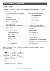
...; Power supply cable (with 7 A fuseholder incorporated) • Spare 7 A fuse -- 2 flat screws -- 2 plain washers -- 2 spring washers -- 2 nuts • 2 M5 x 32 screws with 2 plain washers and 2 nuts (for a recessed installation) • Mounting bracket, with: • Operation Manual -- 4 self-tapping screws • Installation Manual -- 4 flat screws -- 4 plain washers -- 4 spring washers -- 4 nuts -- 2 mounting knobs • Warranty Card • DSC Warning Label • Template for a recessed installation). 6 Lowrance - Link-8 Installation Instructions
...; Power supply cable (with 7 A fuseholder incorporated) • Spare 7 A fuse -- 2 flat screws -- 2 plain washers -- 2 spring washers -- 2 nuts • 2 M5 x 32 screws with 2 plain washers and 2 nuts (for a recessed installation) • Mounting bracket, with: • Operation Manual -- 4 self-tapping screws • Installation Manual -- 4 flat screws -- 4 plain washers -- 4 spring washers -- 4 nuts -- 2 mounting knobs • Warranty Card • DSC Warning Label • Template for a recessed installation). 6 Lowrance - Link-8 Installation Instructions
Link-8 VHF Installation Manual EN
Page 7
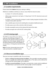
... site and the radio is placed into a bulkhead. The reversible mounting gimbal is fixed to fix the DSC warning label. 2.2 LCD viewing angle The VHF has a large LCD screen with an optimum viewing angle of approx. +/-20 deg. The radio can be adjusted. The radio fixture is recessed ... of the display. The radio is permanent and the viewing angle cannot be removed for a suitable location. Link-8 Installation Instructions 7 Side 20˚ 20˚ Top 20˚ 20˚ 2.3 Choose an installation type There are two ways to (at least) a 10 Amp fused 13.6 V DC electrical source...
... site and the radio is placed into a bulkhead. The reversible mounting gimbal is fixed to fix the DSC warning label. 2.2 LCD viewing angle The VHF has a large LCD screen with an optimum viewing angle of approx. +/-20 deg. The radio can be adjusted. The radio fixture is recessed ... of the display. The radio is permanent and the viewing angle cannot be removed for a suitable location. Link-8 Installation Instructions 7 Side 20˚ 20˚ Top 20˚ 20˚ 2.3 Choose an installation type There are two ways to (at least) a 10 Amp fused 13.6 V DC electrical source...
Link-8 VHF Installation Manual EN
Page 8
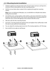
... microphone wall hanger. 8 Lowrance - Use the flat screws, spring washers, plain washers, and nuts to attach the mounting bracket to drill pilot holes before drilling the screw holes. 3. Insert the 2 mounting knobs through the mounting surface. Hold the supplied mounting bracket at the chosen location and use the self-tapping screws instead of the flat screws. 4. Link-8 Installation Instructions Drill the 4 screw...
... microphone wall hanger. 8 Lowrance - Use the flat screws, spring washers, plain washers, and nuts to attach the mounting bracket to drill pilot holes before drilling the screw holes. 3. Insert the 2 mounting knobs through the mounting surface. Hold the supplied mounting bracket at the chosen location and use the self-tapping screws instead of the flat screws. 4. Link-8 Installation Instructions Drill the 4 screw...
Link-8 VHF Installation Manual EN
Page 9
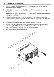
... mounting template and slide the radio into fiberglass, use a small drill bit to the mounting surface using the 2 M5 x 32 screws with the plain washers and nuts. (The screws should not be covered by the radio fascia after installation). 4. Lowrance - Ensure that will be visible from the front of the radio). 6. Drill through the mounting surface. Link-8 Installation Instructions 9 2.3.2 Recessed installation 1. Tape the supplied mounting...
... mounting template and slide the radio into fiberglass, use a small drill bit to the mounting surface using the 2 M5 x 32 screws with the plain washers and nuts. (The screws should not be covered by the radio fascia after installation). 4. Lowrance - Ensure that will be visible from the front of the radio). 6. Drill through the mounting surface. Link-8 Installation Instructions 9 2.3.2 Recessed installation 1. Tape the supplied mounting...
Link-8 VHF Installation Manual EN
Page 11
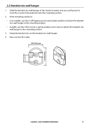
... mic wall hanger to mark the 2 screw hole positions onto the mounting surface. 2. Hang the handset mic on the handset mic wall hanger. 4. If the mounting surface is: • non-metallic, use the 2 self-tapping screws and 2 plain washers to attach the ...handset mic wall hanger to the mounting surface. • metallic, use a soft pencil to the mounting surface. 3. Now connect the radio. 0.96" (24.5 mm) 0.47" (12 mm) 1.16" (29.5 mm) Lowrance - Link-8 Installation Instructions ...
... mic wall hanger to mark the 2 screw hole positions onto the mounting surface. 2. Hang the handset mic on the handset mic wall hanger. 4. If the mounting surface is: • non-metallic, use the 2 self-tapping screws and 2 plain washers to attach the ...handset mic wall hanger to the mounting surface. • metallic, use a soft pencil to the mounting surface. 3. Now connect the radio. 0.96" (24.5 mm) 0.47" (12 mm) 1.16" (29.5 mm) Lowrance - Link-8 Installation Instructions ...
Link-8 VHF Installation Manual EN
Page 12
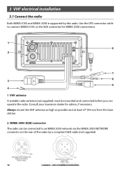
3 VHF electrical installation 3.1 Connect the radio Both NMEA 0183 and NMEA 2000 is supported by a complaint N2K cable (not supplied). 12 Lowrance - Link-8 Installation Instructions Always mount the VHF antenna as high as possible and at least 37" (96 cm) from the base station. 2 NMEA 2000 (N2K) connector The radio can operate the radio. Consult your Lowrance dealer for NMEA 2000 connections. 1 VHF antenna A suitable radio antenna...
3 VHF electrical installation 3.1 Connect the radio Both NMEA 0183 and NMEA 2000 is supported by a complaint N2K cable (not supplied). 12 Lowrance - Link-8 Installation Instructions Always mount the VHF antenna as high as possible and at least 37" (96 cm) from the base station. 2 NMEA 2000 (N2K) connector The radio can operate the radio. Consult your Lowrance dealer for NMEA 2000 connections. 1 VHF antenna A suitable radio antenna...
Link-8 VHF Installation Manual EN
Page 13
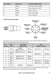
....4 kbps RS422 OUT (+) RS232 OUT (+) 38.4 kbps 38.4 kbps Note: The GPS connector on the GPS cable and plug together. The pin details are shown for information. Lowrance - Link-8 Installation Instructions 13 Pin / Socket 1 2 3 4 5 Wire color Green Red Black White Blue Function (NMEA 2000) Can-D, Drain wire, Shield Can-S, Power, +12 V DC Can-C, Ground Can-H, Data High Can-L, Data Low...
....4 kbps RS422 OUT (+) RS232 OUT (+) 38.4 kbps 38.4 kbps Note: The GPS connector on the GPS cable and plug together. The pin details are shown for information. Lowrance - Link-8 Installation Instructions 13 Pin / Socket 1 2 3 4 5 Wire color Green Red Black White Blue Function (NMEA 2000) Can-D, Drain wire, Shield Can-S, Power, +12 V DC Can-C, Ground Can-H, Data High Can-L, Data Low...
Link-8 VHF Installation Manual EN
Page 14
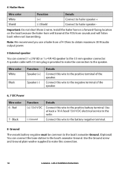
... the connection to the negative terminal of the speaker. 6, 7 DC Power Wire color 6 - Use at least a 10 A fused 13.6 V DC electrical service to the positive terminal of 4 Ohms to obtain maximum 30 W audio output power. 5 External speaker You can connect the base station to the positive battery terminal. Install the hailer horn in a forward-facing location on the boat...
... the connection to the negative terminal of the speaker. 6, 7 DC Power Wire color 6 - Use at least a 10 A fused 13.6 V DC electrical service to the positive terminal of 4 Ohms to obtain maximum 30 W audio output power. 5 External speaker You can connect the base station to the positive battery terminal. Install the hailer horn in a forward-facing location on the boat...
Link-8 VHF Installation Manual EN
Page 15
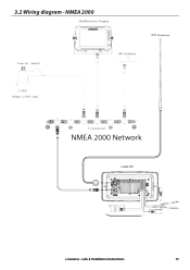
NMEA 2000 Lowrance - 3.2 Wiring diagram - Link-8 Installation Instructions 15
NMEA 2000 Lowrance - 3.2 Wiring diagram - Link-8 Installation Instructions 15
Link-8 VHF Installation Manual EN
Page 16
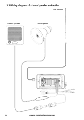
3.3 Wiring diagram - Link-8 Installation Instructions External speaker and hailer VHF Antenna External Speaker Hailer Speaker 16 Lowrance -
3.3 Wiring diagram - Link-8 Installation Instructions External speaker and hailer VHF Antenna External Speaker Hailer Speaker 16 Lowrance -
Link-8 VHF Installation Manual EN
Page 17
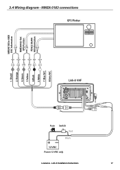
White 7. Shield 2. Orange 4. Blue N/C 8.Grey N/C Fuse Switch Red Black 12 VDC Power 12 VDC only + Lowrance - NMEA 0183 connections GPS Plotter - + - +- + Link-8 VHF 1. Link-8 Installation Instructions 17 Green 5.Yellow 6.Black 3. NMEA0183 In 4800 DSC Information NMEA0183 Out GPS Position RS422 38,400 AIS Information 3.4 Wiring diagram -
White 7. Shield 2. Orange 4. Blue N/C 8.Grey N/C Fuse Switch Red Black 12 VDC Power 12 VDC only + Lowrance - NMEA 0183 connections GPS Plotter - + - +- + Link-8 VHF 1. Link-8 Installation Instructions 17 Green 5.Yellow 6.Black 3. NMEA0183 In 4800 DSC Information NMEA0183 Out GPS Position RS422 38,400 AIS Information 3.4 Wiring diagram -
Link-8 VHF Installation Manual EN
Page 18
See the Setup section in the Link-8 User Guide for full setup details. Link-8 Installation Instructions You must enter your User MMSI before the DSC functions of the rear heat-sink on this radio will work. Caution is advised to prevent possible skin burns. 18 Lowrance - Your user MMSI CAUTION You can't make any DSC transmissions until you've obtained a user MMSI and entered it into your radio - 4 Setup your radio. CAUTION Under extreme operating conditions, the temperature of this radio may exceed normal surface temperatures.
See the Setup section in the Link-8 User Guide for full setup details. Link-8 Installation Instructions You must enter your User MMSI before the DSC functions of the rear heat-sink on this radio will work. Caution is advised to prevent possible skin burns. 18 Lowrance - Your user MMSI CAUTION You can't make any DSC transmissions until you've obtained a user MMSI and entered it into your radio - 4 Setup your radio. CAUTION Under extreme operating conditions, the temperature of this radio may exceed normal surface temperatures.


