Link-8 VHF Installation Manual EN
Page 2
...strictly prohibited. Modifications could result in minor or moderate injury. Copyright © 2013 Navico All rights reserved. Lowrance® is a registered trademark of Navico No part of this symbol to the radio not expressly approved by Navico AS as the responsible entity for its operation and accessories, visit our web site...safety alert symbol. CAUTION CAUTION used to alert you to change or end our policies, regulations, and special offers at any purpose, without notice. Link-8 Installation Instructions Any unauthorized commercial distribution of Lowrance Electronics.
...strictly prohibited. Modifications could result in minor or moderate injury. Copyright © 2013 Navico All rights reserved. Lowrance® is a registered trademark of Navico No part of this symbol to the radio not expressly approved by Navico AS as the responsible entity for its operation and accessories, visit our web site...safety alert symbol. CAUTION CAUTION used to alert you to change or end our policies, regulations, and special offers at any purpose, without notice. Link-8 Installation Instructions Any unauthorized commercial distribution of Lowrance Electronics.
Link-8 VHF Installation Manual EN
Page 3
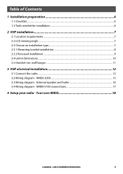
... viewing angle...7 2.3 Choose an installation type...7 2.3.1 Mounting bracket installation...8 2.3.2 Recessed installation...9 2.4 Link-8 dimensions...10 2.5 Handset mic wall hanger...11 3 VHF electrical installation 12 3.1 Connect the radio...12 3.2 Wiring diagram - Link-8 Installation Instructions 3 NMEA 0183 connections 17 4 Setup your radio - Your user MMSI 18 Lowrance - External speaker and hailer 16 3.4 Wiring diagram - NMEA 2000...15 3.3 Wiring diagram -
... viewing angle...7 2.3 Choose an installation type...7 2.3.1 Mounting bracket installation...8 2.3.2 Recessed installation...9 2.4 Link-8 dimensions...10 2.5 Handset mic wall hanger...11 3 VHF electrical installation 12 3.1 Connect the radio...12 3.2 Wiring diagram - Link-8 Installation Instructions 3 NMEA 0183 connections 17 4 Setup your radio - Your user MMSI 18 Lowrance - External speaker and hailer 16 3.4 Wiring diagram - NMEA 2000...15 3.3 Wiring diagram -
Link-8 VHF Installation Manual EN
Page 4
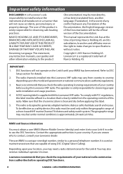
... the time of your country before operating DSC functions. 4 Lowrance - This manual represents the Link-8 as a safety device, this Lowrance VHF radio may also need a radio station license for observing safe boating practices. To comply with this radio. To be used on the Link-8 until your Link-8 in a location that you check the radio operating licensing requirements of the Documentation. MMSI...
... the time of your country before operating DSC functions. 4 Lowrance - This manual represents the Link-8 as a safety device, this Lowrance VHF radio may also need a radio station license for observing safe boating practices. To comply with this radio. To be used on the Link-8 until your Link-8 in a location that you check the radio operating licensing requirements of the Documentation. MMSI...
Link-8 VHF Installation Manual EN
Page 5
... pa produire de brouillage, et (2) l'utilisateur de l'appareil doit accepter tout brouillage radioélectrique subi, même si le brouillage est susceptible d'en compromettre le fonctionnement. Link-8 Installation Instructions 5 This device's antenna must accept any other antenna or transmitter. These... the following measures: Reorient or relocate the receiving antenna. Lowrance - Note: This equipment has been tested and found to comply with the limits for a Class B digital device, pursuant to radio communications. Consult the dealer or an experienced technician for an...
... pa produire de brouillage, et (2) l'utilisateur de l'appareil doit accepter tout brouillage radioélectrique subi, même si le brouillage est susceptible d'en compromettre le fonctionnement. Link-8 Installation Instructions 5 This device's antenna must accept any other antenna or transmitter. These... the following measures: Reorient or relocate the receiving antenna. Lowrance - Note: This equipment has been tested and found to comply with the limits for a Class B digital device, pursuant to radio communications. Consult the dealer or an experienced technician for an...
Link-8 VHF Installation Manual EN
Page 7
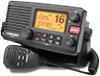
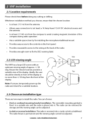
... antenna • Is at the back of the radio • Provides enough room to fix the DSC warning label. 2.2 LCD viewing angle The VHF has a large LCD screen with an optimum viewing angle of the display. The radio is permanent and the viewing angle cannot be adjusted. Lowrance - Link-8 Installation Instructions 7 Note: If unsure, temporarily power...
... antenna • Is at the back of the radio • Provides enough room to fix the DSC warning label. 2.2 LCD viewing angle The VHF has a large LCD screen with an optimum viewing angle of the display. The radio is permanent and the viewing angle cannot be adjusted. Lowrance - Link-8 Installation Instructions 7 Note: If unsure, temporarily power...
Link-8 VHF Installation Manual EN
Page 8
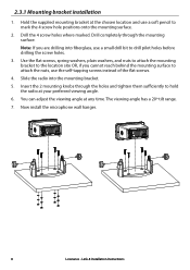
Now install the microphone wall hanger. 8 Lowrance - Drill completely through the holes and tighten them sufficiently to hold the radio at your preferred viewing angle. 6. Insert the 2 mounting knobs through the mounting surface. The viewing angle has a 20º tilt ... the self-tapping screws instead of the flat screws. 4. 2.3.1 Mounting bracket installation 1. Link-8 Installation Instructions Hold the supplied mounting bracket at any time. Drill the 4 screw holes where marked. Slide the radio into fiberglass, use a soft pencil to the location site OR, if you are drilling...
Now install the microphone wall hanger. 8 Lowrance - Drill completely through the holes and tighten them sufficiently to hold the radio at your preferred viewing angle. 6. Insert the 2 mounting knobs through the mounting surface. The viewing angle has a 20º tilt ... the self-tapping screws instead of the flat screws. 4. 2.3.1 Mounting bracket installation 1. Link-8 Installation Instructions Hold the supplied mounting bracket at any time. Drill the 4 screw holes where marked. Slide the radio into fiberglass, use a soft pencil to the location site OR, if you are drilling...
Link-8 VHF Installation Manual EN
Page 9
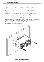
...Working from the front of the radio). 6. Remove the mounting template and slide the radio into fiberglass, use a small drill bit to create a cavity in the mounting surface. (The dashed line shows the total area that the template is smooth and taut. 2. Lowrance - Link-8 Installation Instructions 9 2.3.2 Recessed ...hatched area to drill pilot holes before drilling the screw holes. 3. Drill completely through the corners of the bulkhead, screw the radio firmly to the chosen location. Tape the supplied mounting template to the mounting surface using the 2 M5 x 32 screws with the...
...Working from the front of the radio). 6. Remove the mounting template and slide the radio into fiberglass, use a small drill bit to create a cavity in the mounting surface. (The dashed line shows the total area that the template is smooth and taut. 2. Lowrance - Link-8 Installation Instructions 9 2.3.2 Recessed ...hatched area to drill pilot holes before drilling the screw holes. 3. Drill completely through the corners of the bulkhead, screw the radio firmly to the chosen location. Tape the supplied mounting template to the mounting surface using the 2 M5 x 32 screws with the...
Link-8 VHF Installation Manual EN
Page 11
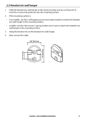
Now connect the radio. 0.96" (24.5 mm) 0.47" (12 mm) 1.16" (29.5 mm) Lowrance - Link-8 Installation Instructions 11 Hang the handset mic on the handset mic wall hanger. 4. Hold the handset mic wall hanger at the chosen location and use ...
Now connect the radio. 0.96" (24.5 mm) 0.47" (12 mm) 1.16" (29.5 mm) Lowrance - Link-8 Installation Instructions 11 Hang the handset mic on the handset mic wall hanger. 4. Hold the handset mic wall hanger at the chosen location and use ...
Link-8 VHF Installation Manual EN
Page 12
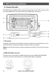
... GPS connector cable to an NMEA 2000 network via the NMEA 2000 NETWORK connector on the rear of the radio by this radio. Link-8 Installation Instructions Consult your Lowrance dealer for NMEA 2000 connections. 1 VHF antenna A suitable radio antenna (not supplied) must be connected to connect NMEA 0183, or the N2K connector for advice, if necessary...
... GPS connector cable to an NMEA 2000 network via the NMEA 2000 NETWORK connector on the rear of the radio by this radio. Link-8 Installation Instructions Consult your Lowrance dealer for NMEA 2000 connections. 1 VHF antenna A suitable radio antenna (not supplied) must be connected to connect NMEA 0183, or the N2K connector for advice, if necessary...
Link-8 VHF Installation Manual EN
Page 13
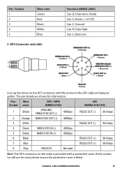
Lowrance - Pin / Wire Socket color 1 Shield 2 Orange 3 White 4 Green 5 Yellow 6 Black 7 Blue 8 Grey GPS / MFD (NMEA 0183) GROUND, NMEA 0183...0183 HS) RS232 OUT (-) 38.4 kbps RS422 OUT (-) 38.4 kbps RS422 OUT (+) RS232 OUT (+) 38.4 kbps 38.4 kbps Note: The GPS connector on the radio is fitted. Pin / Socket 1 2 3 4 5 Wire color Green Red Black White Blue Function (NMEA 2000) Can-D, Drain wire, Shield Can-S, Power, +... IN 8 (Grey) Line up the arrow on the GPS cable and plug together. The pin details are shown for information. Link-8 Installation Instructions 13
Lowrance - Pin / Wire Socket color 1 Shield 2 Orange 3 White 4 Green 5 Yellow 6 Black 7 Blue 8 Grey GPS / MFD (NMEA 0183) GROUND, NMEA 0183...0183 HS) RS232 OUT (-) 38.4 kbps RS422 OUT (-) 38.4 kbps RS422 OUT (+) RS232 OUT (+) 38.4 kbps 38.4 kbps Note: The GPS connector on the radio is fitted. Pin / Socket 1 2 3 4 5 Wire color Green Red Black White Blue Function (NMEA 2000) Can-D, Drain wire, Shield Can-S, Power, +... IN 8 (Grey) Line up the arrow on the GPS cable and plug together. The pin details are shown for information. Link-8 Installation Instructions 13
Link-8 VHF Installation Manual EN
Page 14
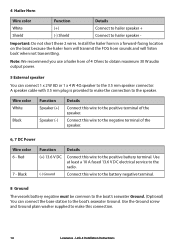
... the 3.5 mm speaker connector. Wire color White Black Function Speaker (+) Speaker (-) Details Connect this wire to make this connection. 14 Lowrance - Red 7 - Install the hailer horn in a forward-facing location on the boat because the hailer horn will transmit the FOG ...937; or 1 x 4 W 4Ω speaker to the boat's seawater Ground. Connect this wire to the speaker. Important: Do not short these 2 wires. Link-8 Installation Instructions Use the Ground screw and Ground plain washer supplied to make the connection to the positive battery terminal. Use at least a 10 A fused...
... the 3.5 mm speaker connector. Wire color White Black Function Speaker (+) Speaker (-) Details Connect this wire to make this connection. 14 Lowrance - Red 7 - Install the hailer horn in a forward-facing location on the boat because the hailer horn will transmit the FOG ...937; or 1 x 4 W 4Ω speaker to the boat's seawater Ground. Connect this wire to the speaker. Important: Do not short these 2 wires. Link-8 Installation Instructions Use the Ground screw and Ground plain washer supplied to make the connection to the positive battery terminal. Use at least a 10 A fused...
Link-8 VHF Installation Manual EN
Page 18
Your user MMSI CAUTION You can't make any DSC transmissions until you've obtained a user MMSI and entered it into your radio - See the Setup section in the Link-8 User Guide for full setup details. CAUTION Under extreme operating conditions, the temperature of this radio may exceed normal surface temperatures. Link-8 Installation Instructions Caution is advised to prevent possible skin burns. 18 Lowrance - You must enter your User MMSI before the DSC functions of the rear heat-sink on this radio will work. 4 Setup your radio.
Your user MMSI CAUTION You can't make any DSC transmissions until you've obtained a user MMSI and entered it into your radio - See the Setup section in the Link-8 User Guide for full setup details. CAUTION Under extreme operating conditions, the temperature of this radio may exceed normal surface temperatures. Link-8 Installation Instructions Caution is advised to prevent possible skin burns. 18 Lowrance - You must enter your User MMSI before the DSC functions of the rear heat-sink on this radio will work. 4 Setup your radio.