
SL595 Manual
Page 2
... from something Gate System Test Procedures 13 mechanical or from electric shock. Model SL585 34 Repair Parts - AVERTISSEMENT Control Connection Diagrams 17 Radio Receiver 18-19 Accessory Wiring 19-20 CARTON INVENTORY ATTEN AVERT Earth Ground Rod Installation 21 ATTENTION AVER Sequenced... Friction Clutch 24 HARDWARE KIT SL585/SL595 (K77-34846) Control Board Programming and Features 24-25 AVER Troubleshooting 26-27 Self-Regulating Heater Accessory 28 Single Phase Wiring Diagram 29 Single Phase Schematic 30 Three Phase Wiring Diagram 31 Three Phase Schematic 32...
... from something Gate System Test Procedures 13 mechanical or from electric shock. Model SL585 34 Repair Parts - AVERTISSEMENT Control Connection Diagrams 17 Radio Receiver 18-19 Accessory Wiring 19-20 CARTON INVENTORY ATTEN AVERT Earth Ground Rod Installation 21 ATTENTION AVER Sequenced... Friction Clutch 24 HARDWARE KIT SL585/SL595 (K77-34846) Control Board Programming and Features 24-25 AVER Troubleshooting 26-27 Self-Regulating Heater Accessory 28 Single Phase Wiring Diagram 29 Single Phase Schematic 30 Three Phase Wiring Diagram 31 Three Phase Schematic 32...
SL595 Manual
Page 8
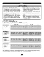
... (3898.1 m) 15987 ft. (4872.8 m) 1278 ft. (389.5 m) 5115 ft. (1559.1 m) 7993 ft. (2436.3 m) 639 ft. (194.8 m) 2557 ft. (779.4 m) 4441 ft. (1353.6 m) WIRE GAUGE 8 • 1/2 HP Motor ------• 1 HP Motor 2 HP Motor --------- Local codes and conditions must be performed until disconnecting the electrical power and locking-out the... power disconnect should be dedicated and protected. AVERTISSEMENT • ALL electrical connections MUST be run the operator without consulting the wiring diagram. Failure to do so may be sure to follow ALL specifications and warnings described below.
... (3898.1 m) 15987 ft. (4872.8 m) 1278 ft. (389.5 m) 5115 ft. (1559.1 m) 7993 ft. (2436.3 m) 639 ft. (194.8 m) 2557 ft. (779.4 m) 4441 ft. (1353.6 m) WIRE GAUGE 8 • 1/2 HP Motor ------• 1 HP Motor 2 HP Motor --------- Local codes and conditions must be performed until disconnecting the electrical power and locking-out the... power disconnect should be dedicated and protected. AVERTISSEMENT • ALL electrical connections MUST be run the operator without consulting the wiring diagram. Failure to do so may be sure to follow ALL specifications and warnings described below.
SL595 Manual
Page 12
... disconnect lever and lock it in place. ON/OFF SWITCH POWER WIRING NOTES: Before running power wiring refer to disengage. MANUAL DISCONNECT MODEL SL585 DISENGAGEMENT: RE-ENGAGEMENT: Rotate disconnect handle 90˚ to wiring specifications on pages 29-32. Rotate handle back to original position.... conduit connectors. On three phase operators, power connections must be required for engagement.) Pull the handle to electrical wiring diagrams on page 8 for correct wire gauges. Release the lever and close the door. (Some operator output sprocket rotation may be moved manually.
... disconnect lever and lock it in place. ON/OFF SWITCH POWER WIRING NOTES: Before running power wiring refer to disengage. MANUAL DISCONNECT MODEL SL585 DISENGAGEMENT: RE-ENGAGEMENT: Rotate disconnect handle 90˚ to wiring specifications on pages 29-32. Rotate handle back to original position.... conduit connectors. On three phase operators, power connections must be required for engagement.) Pull the handle to electrical wiring diagrams on page 8 for correct wire gauges. Release the lever and close the door. (Some operator output sprocket rotation may be moved manually.
SL595 Manual
Page 17
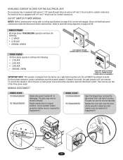
... R4 Accessory Terminal Block 1 2 3 4 5 6 7 8 9 10 11 12 13 14 15 16 17 18 19 20 24 Vac Control Board SINGLE PHASE ELECTRICAL BOX NOTE: See wiring diagrams shipped with the gate while operating the controls where the user has full view of gate operation. * We strongly recommend that you follow the instructions...
... R4 Accessory Terminal Block 1 2 3 4 5 6 7 8 9 10 11 12 13 14 15 16 17 18 19 20 24 Vac Control Board SINGLE PHASE ELECTRICAL BOX NOTE: See wiring diagrams shipped with the gate while operating the controls where the user has full view of gate operation. * We strongly recommend that you follow the instructions...
SL595 Manual
Page 28
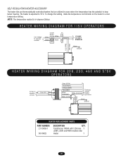
... (208V) White (Common) White (Common) Black (120V) Terminate unused transfer input wires Green Ground Black (N) Black (T1) HEATER REPLACEMENT PARTS PART NUMBER 21-15453-1 50-18423 DESCRIPTION QTY. HEATER WIRING DIAGRAM FOR 115V OPERATORS Line voltage to operator controls On/Off Switch White ON White Black ...Black OFF L1 1 PHASE L2 115 VOLT POWER IN Green Ground Black (N) Black (T1) HEATER WIRING DIAGRAM FOR 208, 230, 460 AND 575V OPERATORS 24 Vac to drop below freezing. SELF-REGULATING HEATER ACCESSORY The heater kits are ...
... (208V) White (Common) White (Common) Black (120V) Terminate unused transfer input wires Green Ground Black (N) Black (T1) HEATER REPLACEMENT PARTS PART NUMBER 21-15453-1 50-18423 DESCRIPTION QTY. HEATER WIRING DIAGRAM FOR 115V OPERATORS Line voltage to operator controls On/Off Switch White ON White Black ...Black OFF L1 1 PHASE L2 115 VOLT POWER IN Green Ground Black (N) Black (T1) HEATER WIRING DIAGRAM FOR 208, 230, 460 AND 575V OPERATORS 24 Vac to drop below freezing. SELF-REGULATING HEATER ACCESSORY The heater kits are ...
SL595 Manual
Page 29
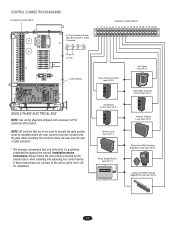
... SOLENOID (GY) (SL595 GN) 1 (BL/BK) TO REVERSE MOTOR DIRECTION INTERCHANGE PURPLE & GRAY WIRES ON MODEL SL585 OR THE RED & GREEN WIRES ON MODEL SL595 INTERNAL MOTOR WIRING 1 - BROWN GL CONTROL BOARD J2 PLUG 24VAC-IN 24VAC-COMMON SOFT OPEN NC "B" LIMIT CONTACTOR ... 5) 4 (GN) 6 (WH) 7 (RD) 8 (BK) 9 (BRN) 10 (GY) FREE EXIT LOOP HARNESS 10 PIN - 1,2,3,5 CAPPED 4 - SINGLE PHASE WIRING DIAGRAM WARNING To protect against fire and electrocution: • DISCONNECT power BEFORE installing or servicing operator. • Replace ONLY with an additional internal pilot duty thermal...
... SOLENOID (GY) (SL595 GN) 1 (BL/BK) TO REVERSE MOTOR DIRECTION INTERCHANGE PURPLE & GRAY WIRES ON MODEL SL585 OR THE RED & GREEN WIRES ON MODEL SL595 INTERNAL MOTOR WIRING 1 - BROWN GL CONTROL BOARD J2 PLUG 24VAC-IN 24VAC-COMMON SOFT OPEN NC "B" LIMIT CONTACTOR ... 5) 4 (GN) 6 (WH) 7 (RD) 8 (BK) 9 (BRN) 10 (GY) FREE EXIT LOOP HARNESS 10 PIN - 1,2,3,5 CAPPED 4 - SINGLE PHASE WIRING DIAGRAM WARNING To protect against fire and electrocution: • DISCONNECT power BEFORE installing or servicing operator. • Replace ONLY with an additional internal pilot duty thermal...

SL595 Manual
Page 31
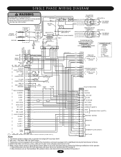
...18 (GY) 19 (BRN) 20 INTERRUPT LOOP (SAFETY) EXIT LOOP NOTES: 1. Secondary 24V 60VA. 2. Remove the green wire from radio block R4) to terminal block TB1 position 6. 2. Wire color: 208V red, 230V orange, 460V purple, 575V gray. 3. Transformer primary voltage is the same as the operator line ... and rating. Three phase units are equipped with fuse of the Soft Open feature, perform the following modifications to the operator: 1. THREE PHASE WIRING DIAGRAM 3 PHASE POWER IN ON/OFF SWITCH L1 (BK) L2 (BK) L3 (BK) GROUND (GN) WARNING To protect against fire and electrocution...
...18 (GY) 19 (BRN) 20 INTERRUPT LOOP (SAFETY) EXIT LOOP NOTES: 1. Secondary 24V 60VA. 2. Remove the green wire from radio block R4) to terminal block TB1 position 6. 2. Wire color: 208V red, 230V orange, 460V purple, 575V gray. 3. Transformer primary voltage is the same as the operator line ... and rating. Three phase units are equipped with fuse of the Soft Open feature, perform the following modifications to the operator: 1. THREE PHASE WIRING DIAGRAM 3 PHASE POWER IN ON/OFF SWITCH L1 (BK) L2 (BK) L3 (BK) GROUND (GN) WARNING To protect against fire and electrocution...


