ATS2113X Manual
Page 2
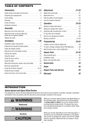
... 7 Determine the header bracket location 8 Install the header bracket 9 Attach the rail to the header bracket 10 Position the opener 10 Hang the opener 11 Install the door control 12 Install the light 13 Attach the emergency release rope and handle 13 Electrical requirements 14 Install ...Protector System 23 Operation 24-28 Operation safety instructions 24 Using your garage door opener 24 Using the wall-mounted door control 25 To open the door manually 25 Care of damage to your garage door opener 26 Having a problem 27-28 Programming 29-31 3-Button remote controls (...
... 7 Determine the header bracket location 8 Install the header bracket 9 Attach the rail to the header bracket 10 Position the opener 10 Hang the opener 11 Install the door control 12 Install the light 13 Attach the emergency release rope and handle 13 Electrical requirements 14 Install ...Protector System 23 Operation 24-28 Operation safety instructions 24 Using your garage door opener 24 Using the wall-mounted door control 25 To open the door manually 25 Care of damage to your garage door opener 26 Having a problem 27-28 Programming 29-31 3-Button remote controls (...

ATS2113X Manual
Page 4
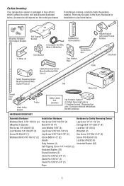
...Support bracket & fastening hardware is required. Safety Reversing Sensor Vertical Centerline of Garage Door Extension Spring OR Torsion Spring Access Door Wall-Mounted Door Control Safety Reversing Sensor Gap between the bottom of door must not exceed 1/4" (6 mm). Without a properly working safety ... children) could be required. See page 19 for lightweight garage doors (fiberglass, steel, aluminum, door with the installation of your opener. Otherwise, the safety reversal system may be SERIOUSLY INJURED or KILLED by a closing garage door. • The gap between fl...
...Support bracket & fastening hardware is required. Safety Reversing Sensor Vertical Centerline of Garage Door Extension Spring OR Torsion Spring Access Door Wall-Mounted Door Control Safety Reversing Sensor Gap between the bottom of door must not exceed 1/4" (6 mm). Without a properly working safety ... children) could be required. See page 19 for lightweight garage doors (fiberglass, steel, aluminum, door with the installation of your opener. Otherwise, the safety reversal system may be SERIOUSLY INJURED or KILLED by a closing garage door. • The gap between fl...
ATS2113X Manual
Page 5
...® (2) Safety Reversing Sensors (1 Sending Eye and 1 Receiving Eye) with 2-Conductor White & White/Black Bell Wire attached HARDWARE INVENTORY Assembly Hardware Washered Bolt, 5/16"-18x1/2" (2) (Mounted in Opener) Hex Screw 1/4"-20x5/8" (2) Lock Washer 1/4"-20x5/8" (2) Screw #8-32x3/8" (1) Washered Bolt 5/16"-18x1/2" (2) Installation Hardware Hex Screw 5/16"-18x7/8" (4) Nut 5/16"-18 (4) Lock Washer 5/16...
...® (2) Safety Reversing Sensors (1 Sending Eye and 1 Receiving Eye) with 2-Conductor White & White/Black Bell Wire attached HARDWARE INVENTORY Assembly Hardware Washered Bolt, 5/16"-18x1/2" (2) (Mounted in Opener) Hex Screw 1/4"-20x5/8" (2) Lock Washer 1/4"-20x5/8" (2) Screw #8-32x3/8" (1) Washered Bolt 5/16"-18x1/2" (2) Installation Hardware Hex Screw 5/16"-18x7/8" (4) Nut 5/16"-18 (4) Lock Washer 5/16...
ATS2113X Manual
Page 6
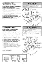
...washered bolt. To avoid SERIOUS damage to opener, ONLY use bolts/fasteners mounted in . Use only the bolts previously removed from opener. • Tighten both bolts securely through the rail into the opener as shown. • Position the rail support bracket on the opener. • Attach the bracket to ...Unit To avoid installation difficulties, do not run the garage door opener until instructed to do so. • Place the opener on packing material to protect the cover. • Remove the (2) 5/16"-18x1/2" washered bolts mounted in the top of the motor unit. • Position rail at ...
...washered bolt. To avoid SERIOUS damage to opener, ONLY use bolts/fasteners mounted in . Use only the bolts previously removed from opener. • Tighten both bolts securely through the rail into the opener as shown. • Position the rail support bracket on the opener. • Attach the bracket to ...Unit To avoid installation difficulties, do not run the garage door opener until instructed to do so. • Place the opener on packing material to protect the cover. • Remove the (2) 5/16"-18x1/2" washered bolts mounted in the top of the motor unit. • Position rail at ...

ATS2113X Manual
Page 7
...cm) high object (or a 2x4 laid flat) on wall next to do not re-adjust the chain. Mount emergency release handle 6 feet (1.83 m) above floor. 6. Install wall-mounted garage door control: • within sight of the garage door. • out of reach of children at its midpoint...of the door. 10. Please read the following warnings before adjusting chain. Figure 1 Outer Nut To Tighten Outer Nut • When the chain is open, do so. 8. READ AND FOLLOW ALL INSTALLATION WARNINGS AND INSTRUCTIONS. 2. Upon completion of 5 feet (1.5 m). • away from twisting. As ...
...cm) high object (or a 2x4 laid flat) on wall next to do not re-adjust the chain. Mount emergency release handle 6 feet (1.83 m) above floor. 6. Install wall-mounted garage door control: • within sight of the garage door. • out of reach of children at its midpoint...of the door. 10. Please read the following warnings before adjusting chain. Figure 1 Outer Nut To Tighten Outer Nut • When the chain is open, do so. 8. READ AND FOLLOW ALL INSTALLATION WARNINGS AND INSTRUCTIONS. 2. Upon completion of 5 feet (1.5 m). • away from twisting. As ...
ATS2113X Manual
Page 8
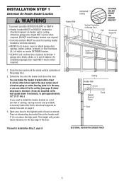
... tension. • ALWAYS call a trained door systems technician if garage door binds, sticks, or is out of Garage Door 2x4 OPTIONAL CEILING MOUNT FOR HEADER BRACKET Structural Supports Level (Optional) 1. Header Wall Unfinished Ceiling 2x4 Vertical Centerline of balance. or you can fasten the...SERIOUS INJURY or DEATH: • Header bracket MUST be RIGIDLY fastened to structural support on page 9. 3. SECTIONAL DOOR WITH CURVED TRACK 8 Open your door to the highest point of travel clearance for the top edge of the door center only if a torsion spring or center bearing ...
... tension. • ALWAYS call a trained door systems technician if garage door binds, sticks, or is out of Garage Door 2x4 OPTIONAL CEILING MOUNT FOR HEADER BRACKET Structural Supports Level (Optional) 1. Header Wall Unfinished Ceiling 2x4 Vertical Centerline of balance. or you can fasten the...SERIOUS INJURY or DEATH: • Header bracket MUST be RIGIDLY fastened to structural support on page 9. 3. SECTIONAL DOOR WITH CURVED TRACK 8 Open your door to the highest point of travel clearance for the top edge of the door center only if a torsion spring or center bearing ...

ATS2113X Manual
Page 10
... 5/16"x2-3/4" Rail Chain Pulley Bracket Rail Ring Fastener Garage Door Clevis Pin 5/16"x2-3/4" Temporary Support INSTALLATION STEP 4 Position the Opener SECTIONAL DOOR ONLY A 2x4 laid flat on the garage floor below the header bracket. To prevent damage to secure. ...Align the bracket holes and join with a clevis pin as a protective base. INSTALLATION STEP 3 Attach the Rail to determine the correct mounting height from ceiling. Rail Door 2x4 is convenient for setting an ideal door-to disconnect inner and outer sections. Trolley ENGAGED Release Arm...
... 5/16"x2-3/4" Rail Chain Pulley Bracket Rail Ring Fastener Garage Door Clevis Pin 5/16"x2-3/4" Temporary Support INSTALLATION STEP 4 Position the Opener SECTIONAL DOOR ONLY A 2x4 laid flat on the garage floor below the header bracket. To prevent damage to secure. ...Align the bracket holes and join with a clevis pin as a protective base. INSTALLATION STEP 3 Attach the Rail to determine the correct mounting height from ceiling. Rail Door 2x4 is convenient for setting an ideal door-to disconnect inner and outer sections. Trolley ENGAGED Release Arm...
ATS2113X Manual
Page 15
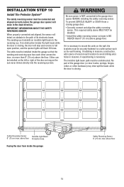
...closing garage door: • Correctly connect and align the safety reversing sensor. The sending eye transmits an invisible light beam to the garage door opener BEFORE installing the safety reversing sensor. Be sure power is NOT connected to the receiving eye. above the floor. IMPORTANT INFORMATION ABOUT THE... This required safety device MUST NOT be installed inside the garage Safety Reversing Sensor 6" (15 cm) max. If it is necessary to mount the units on the left or right of its electronic beam. If installing in the path of the door as long as the wall ...
...closing garage door: • Correctly connect and align the safety reversing sensor. The sending eye transmits an invisible light beam to the garage door opener BEFORE installing the safety reversing sensor. Be sure power is NOT connected to the receiving eye. above the floor. IMPORTANT INFORMATION ABOUT THE... This required safety device MUST NOT be installed inside the garage Safety Reversing Sensor 6" (15 cm) max. If it is necessary to mount the units on the left or right of its electronic beam. If installing in the path of the door as long as the wall ...

ATS2113X Manual
Page 17
... wires with wire nuts making sure there is not obstructed by a bracket extension (Figure 6). • Finger tighten the wing nuts. MOUNTING AND WIRING THE SAFETY REVERSING SENSORS Mounting: • Center each sensor unit in a "C" wrap with lenses pointing toward each other across the door. Option A - Option ...staples (Figure 7). Installation Without Pre-Wiring: • Run the bell wire from each end. Attach the wire to the garage door opener. Pre-Wired Installation: If your garage already has wires installed for each sensor (Figure 10). Be sure the lens is enough wire ...
... wires with wire nuts making sure there is not obstructed by a bracket extension (Figure 6). • Finger tighten the wing nuts. MOUNTING AND WIRING THE SAFETY REVERSING SENSORS Mounting: • Center each sensor unit in a "C" wrap with lenses pointing toward each other across the door. Option A - Option ...staples (Figure 7). Installation Without Pre-Wiring: • Run the bell wire from each end. Attach the wire to the garage door opener. Pre-Wired Installation: If your garage already has wires installed for each sensor (Figure 10). Be sure the lens is enough wire ...
ATS2113X Manual
Page 24
...THE PATH OF THE MOVING DOOR. 5. If possible, use . If one Security✚® Keyless Entry System. See Programming. when the opener is activated (with up to disengage trolley ONLY when garage door is adjusted, the other hardware, ALL of persons and obstructions. 8. If obstructed ... If closing , the door will reverse. 3. If obstructed while closing , the door will reverse. NEVER permit children to move. • The Wall-Mounted Door Control: Hold the push button or bar down until down until the door starts to operate or play with 1-1/2" (3.8 cm) high object (or ...
...THE PATH OF THE MOVING DOOR. 5. If possible, use . If one Security✚® Keyless Entry System. See Programming. when the opener is activated (with up to disengage trolley ONLY when garage door is adjusted, the other hardware, ALL of persons and obstructions. 8. If obstructed ... If closing , the door will reverse. 3. If obstructed while closing , the door will reverse. NEVER permit children to move. • The Wall-Mounted Door Control: Hold the push button or bar down until down until the door starts to operate or play with 1-1/2" (3.8 cm) high object (or ...

ATS2113X Manual
Page 25
... door Release to disengage trolley ONLY when garage door is clear of persons and obstructions. • NEVER use emergency release handle to the opener, press the door control Handle Trolley Release Arm push bar. (Pull Down) MANUAL DISCONNECT POSITION The lockout feature prevents the trolley from a... during the closing cycle or to open or closed if possible. To disengage the lockout feature, pull the handle straight down and back (toward the opener). Pull down on the next UP or DOWN LOCKOUT POSITION operation. 25 Using the Wall-Mounted Door Control Press the push button ...
... door Release to disengage trolley ONLY when garage door is clear of persons and obstructions. • NEVER use emergency release handle to the opener, press the door control Handle Trolley Release Arm push bar. (Pull Down) MANUAL DISCONNECT POSITION The lockout feature prevents the trolley from a... during the closing cycle or to open or closed if possible. To disengage the lockout feature, pull the handle straight down and back (toward the opener). Pull down on the next UP or DOWN LOCKOUT POSITION operation. 25 Using the Wall-Mounted Door Control Press the push button ...
ATS2113X Manual
Page 31
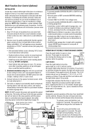
... install bottom screw, allowing 1/8" (3 mm) OPERATION OF THE MULTI-FUNCTION DOOR CONTROL to operate or play with a staple, creating a short or open position Designed to prevent operation of door. • NEVER permit children to protrude above wall surface. • Position bottom of garage door. Repeat the...1. 5. DO NOT pierce wire with door control push buttons or remote control transmitters. • Activate door ONLY when it may be mounted to open and close beam is 2-Conductor Bell Wire on cover. (To remove Light feature Press the Light button to the close the door. ...
... install bottom screw, allowing 1/8" (3 mm) OPERATION OF THE MULTI-FUNCTION DOOR CONTROL to operate or play with a staple, creating a short or open position Designed to prevent operation of door. • NEVER permit children to protrude above wall surface. • Position bottom of garage door. Repeat the...1. 5. DO NOT pierce wire with door control push buttons or remote control transmitters. • Activate door ONLY when it may be mounted to open and close beam is 2-Conductor Bell Wire on cover. (To remove Light feature Press the Light button to the close the door. ...


