3275 Manual
Page 1
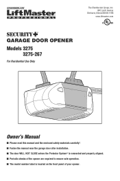
The Chamberlain Group, Inc. 845 Larch Avenue Elmhurst, Illinois 60126-1196 www.liftmaster.com ® GARAGE DOOR OPENER Models 3275 3275-267 For Residential Use Only Owner's Manual ■ Please read this manual and the enclosed safety materials carefully! ■ Fasten the manual near the garage door after installation. ■ The door WILL NOT CLOSE unless the Protector System® is connected and properly aligned. ■ Periodic checks of the opener are required to ensure safe operation. ■ The model number label is located on the front panel of your opener.
The Chamberlain Group, Inc. 845 Larch Avenue Elmhurst, Illinois 60126-1196 www.liftmaster.com ® GARAGE DOOR OPENER Models 3275 3275-267 For Residential Use Only Owner's Manual ■ Please read this manual and the enclosed safety materials carefully! ■ Fasten the manual near the garage door after installation. ■ The door WILL NOT CLOSE unless the Protector System® is connected and properly aligned. ■ Periodic checks of the opener are required to ensure safe operation. ■ The model number label is located on the front panel of your opener.
3275 Manual
Page 2
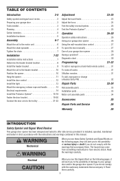
... 7 Determine the header bracket location 8 Install the header bracket 9 Attach the rail to the header bracket 10 Position the opener 10 Hang the opener 11 Install the door control 12 Install the light 13 Attach the emergency release rope and handle 13 Electrical requirements 14 Install the...unit assembly parts 34 Accessories 35 Repair Parts and Service 36 Warranty 36 INTRODUCTION Safety Symbol and Signal Word Review This garage door opener has been designed and tested to offer safe service provided it is installed, operated, maintained and tested in this Signal Word on...
... 7 Determine the header bracket location 8 Install the header bracket 9 Attach the rail to the header bracket 10 Position the opener 10 Hang the opener 11 Install the door control 12 Install the light 13 Attach the emergency release rope and handle 13 Electrical requirements 14 Install the...unit assembly parts 34 Accessories 35 Repair Parts and Service 36 Warranty 36 INTRODUCTION Safety Symbol and Signal Word Review This garage door opener has been designed and tested to offer safe service provided it is installed, operated, maintained and tested in this Signal Word on...
3275 Manual
Page 3
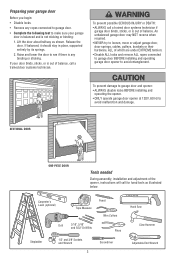
SECTIONAL DOOR ONE-PIECE DOOR Tools needed During assembly, installation and adjustment of the opener, instructions will call a trained door systems technician if garage door binds, sticks, or is out of balance. To prevent possible SERIOUS INJURY or DEATH... ropes connected to garage door BEFORE installing and operating garage door opener to avoid malfunction and damage. To prevent damage to garage door and opener: • ALWAYS disable locks BEFORE installing and operating the opener. • ONLY operate garage door opener at 120V, 60 Hz to avoid entanglement. Release the door....
SECTIONAL DOOR ONE-PIECE DOOR Tools needed During assembly, installation and adjustment of the opener, instructions will call a trained door systems technician if garage door binds, sticks, or is out of balance. To prevent possible SERIOUS INJURY or DEATH... ropes connected to garage door BEFORE installing and operating garage door opener to avoid malfunction and damage. To prevent damage to garage door and opener: • ALWAYS disable locks BEFORE installing and operating the opener. • ONLY operate garage door opener at 120V, 60 Hz to avoid entanglement. Release the door....

3275 Manual
Page 4
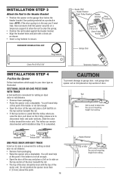
... with glass panels, etc.). You may be required. See page 20 for lightweight garage doors (fiberglass, steel, aluminum, door with the installation of your opener. Header Wall FINISHED CEILING Support bracket & fastening hardware is closed Extension Spring OR Torsion Spring Motor unit Vertical Centerline of Garage Door OR One-Piece...
... with glass panels, etc.). You may be required. See page 20 for lightweight garage doors (fiberglass, steel, aluminum, door with the installation of your opener. Header Wall FINISHED CEILING Support bracket & fastening hardware is closed Extension Spring OR Torsion Spring Motor unit Vertical Centerline of Garage Door OR One-Piece...
3275 Manual
Page 5
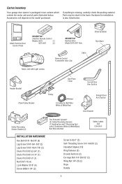
... installation is missing, carefully check the packing material. Carton Inventory Your garage door opener is packaged in the foam. Multi-Function Door Control Panel SECURITY✚® 3-Button Remote Control Models 3275 (1) 3275-267 (2) SECURITY✚® Keyless Entry Model 3275-267 Only Remote Control Transmitter Visor Clip Chain Motor Unit with Light Lenses...
... installation is missing, carefully check the packing material. Carton Inventory Your garage door opener is packaged in the foam. Multi-Function Door Control Panel SECURITY✚® 3-Button Remote Control Models 3275 (1) 3275-267 (2) SECURITY✚® Keyless Entry Model 3275-267 Only Remote Control Transmitter Visor Clip Chain Motor Unit with Light Lenses...
3275 Manual
Page 6
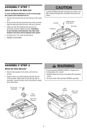
Hex Screws 8-32x7/16" Chain Spreader Motor Unit Sprocket To avoid possible SERIOUS INJURY to fingers from moving garage door opener: • ALWAYS keep hand clear of the spreader. Tighten securely. Lock Nut T-Rail Hole Washered Bolt 5/16"-18x1/2" Styrofoam ASSEMBLY STEP 2 Attach the Chain Spreader ... only these bolts/fasteners! ASSEMBLY STEP 1 Attach the Rail to the Motor Unit To avoid installation difficulties, do not run the garage door opener until instructed to do so. • Remove the bolt and lock nut from the top of the motor unit. • Place rail onto the ...
Hex Screws 8-32x7/16" Chain Spreader Motor Unit Sprocket To avoid possible SERIOUS INJURY to fingers from moving garage door opener: • ALWAYS keep hand clear of the spreader. Tighten securely. Lock Nut T-Rail Hole Washered Bolt 5/16"-18x1/2" Styrofoam ASSEMBLY STEP 2 Attach the Chain Spreader ... only these bolts/fasteners! ASSEMBLY STEP 1 Attach the Rail to the Motor Unit To avoid installation difficulties, do not run the garage door opener until instructed to do so. • Remove the bolt and lock nut from the top of the motor unit. • Place rail onto the ...
3275 Manual
Page 7
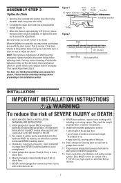
... Mount emergency release handle 6 feet (1.83 m) above floor. 6. NEVER wear watches, rings or loose clothing while installing or servicing opener. Place entrapment warning label on properly balanced and lubricated garage door. READ AND FOLLOW ALL INSTALLATION WARNINGS AND INSTRUCTIONS. 2. They could result in... When the chain is approximately 1/2" (13 mm) above the base of Rail adjusting chain. When installation is too loose. This is open, do so. 8. Chain 1/2" (13 mm) WARNING NOTE: During future maintenance, ALWAYS pull the emergency release handle to disconnect trolley ...
... Mount emergency release handle 6 feet (1.83 m) above floor. 6. NEVER wear watches, rings or loose clothing while installing or servicing opener. Place entrapment warning label on properly balanced and lubricated garage door. READ AND FOLLOW ALL INSTALLATION WARNINGS AND INSTRUCTIONS. 2. They could result in... When the chain is approximately 1/2" (13 mm) above the base of Rail adjusting chain. When installation is too loose. This is open, do so. 8. Chain 1/2" (13 mm) WARNING NOTE: During future maintenance, ALWAYS pull the emergency release handle to disconnect trolley ...
3275 Manual
Page 8
... inside vertical centerline of Garage Door OPTIONAL CEILING MOUNT FOR HEADER BRACKET 2x4 Structural Supports Level (optional) Installation procedures vary according to garage door types. Open your door. 1. Header Wall 2" (5 cm) Track Highest Door Point of Travel Door Header Wall 2" (5 cm) Track Highest Point of Travel Sectional door with curved track...
... inside vertical centerline of Garage Door OPTIONAL CEILING MOUNT FOR HEADER BRACKET 2x4 Structural Supports Level (optional) Installation procedures vary according to garage door types. Open your door. 1. Header Wall 2" (5 cm) Track Highest Door Point of Travel Door Header Wall 2" (5 cm) Track Highest Point of Travel Sectional door with curved track...
3275 Manual
Page 10
... you 'll need help . Slide the outer trolley toward the motor unit. To prevent damage to your door type as illustrated. Do not position the opener more than 4" (10 cm) above this point if the ladder is completed. NOTE: If the door spring is used to disconnect inner and outer sections...;at this point. 10 Header Bracket Top of the motor unit. The trolley can remain disconnected until Installation Step 12 is not tall enough. • Open the door all the way and place a 2x4 on top section of the door should be level with a clevis pin as a protective base. ENGAGED Trolley...
... you 'll need help . Slide the outer trolley toward the motor unit. To prevent damage to your door type as illustrated. Do not position the opener more than 4" (10 cm) above this point if the ladder is completed. NOTE: If the door spring is used to disconnect inner and outer sections...;at this point. 10 Header Bracket Top of the motor unit. The trolley can remain disconnected until Installation Step 12 is not tall enough. • Open the door all the way and place a 2x4 on top section of the door should be level with a clevis pin as a protective base. ENGAGED Trolley...
3275 Manual
Page 11
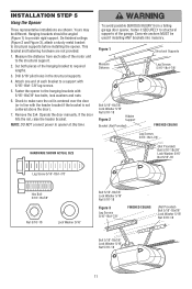
... fastening hardware are shown. Drill 3/16" pilot holes in line with 5/16"-18x7/8" hex bolts, lock washers and nuts. 6. Fasten the opener to a support with 5/16"-18x1-7/8" lag screws. 5. Attach one end of each side of the motor unit to required lengths. 3. Figure... installing ANY brackets into masonry. Hanging brackets should be angled (Figure 1) to structural supports before installing the opener. Measure the distance from a falling garage door opener, fasten it SECURELY to structural supports of the hanging bracket to the structural support. 2. INSTALLATION STEP 5 ...
... fastening hardware are shown. Drill 3/16" pilot holes in line with 5/16"-18x7/8" hex bolts, lock washers and nuts. 6. Fasten the opener to a support with 5/16"-18x1-7/8" lag screws. 5. Attach one end of each side of the motor unit to required lengths. 3. Figure... installing ANY brackets into masonry. Hanging brackets should be angled (Figure 1) to structural supports before installing the opener. Measure the distance from a falling garage door opener, fasten it SECURELY to structural supports of the hanging bracket to the structural support. 2. INSTALLATION STEP 5 ...
3275 Manual
Page 12
... above wall surface. • Position bottom of door. • NEVER permit children to operate or play with a staple, creating a short or open position but will not function (reverse wires to avoid cracking plastic housing. Strip 7/16" (11 mm) of insulation from ALL moving parts of garage...a click is NOT connected BEFORE installing door control. • Connect ONLY to the RED (Figure 3). 2. NOTE: DO NOT connect power and operate opener at . Strip 7/16" (11 mm) of insulation from electrocution: • Be sure power is not heard when pressing the push bar, loosen...
... above wall surface. • Position bottom of door. • NEVER permit children to operate or play with a staple, creating a short or open position but will not function (reverse wires to avoid cracking plastic housing. Strip 7/16" (11 mm) of insulation from ALL moving parts of garage...a click is NOT connected BEFORE installing door control. • Connect ONLY to the RED (Figure 3). 2. NOTE: DO NOT connect power and operate opener at . Strip 7/16" (11 mm) of insulation from electrocution: • Be sure power is not heard when pressing the push bar, loosen...
3275 Manual
Page 13
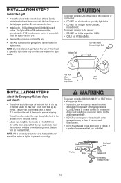
... speciality light bulbs may overheat the endpanel or light socket. The use handle to close the lens. • Use A19, standard neck garage door opener bulbs for approximately 4-1/2 minutes when power is CLOSED. Use ONLY incandescent. Secure with an overhand knot at least 1" (2.5 cm) from a falling ...replacement. NOTE: If it is 6 feet (1.83 m) above the floor. NOTE: Use only standard light bulbs. To prevent damage to the opener: • DO NOT use bulbs larger than 100W. • ONLY use emergency release handle to avoid entanglement. Then the lights will turn OFF....
... speciality light bulbs may overheat the endpanel or light socket. The use handle to close the lens. • Use A19, standard neck garage door opener bulbs for approximately 4-1/2 minutes when power is CLOSED. Use ONLY incandescent. Secure with an overhand knot at least 1" (2.5 cm) from a falling ...replacement. NOTE: If it is 6 feet (1.83 m) above the floor. NOTE: Use only standard light bulbs. To prevent damage to the opener: • DO NOT use bulbs larger than 100W. • ONLY use emergency release handle to avoid entanglement. Then the lights will turn OFF....
3275 Manual
Page 14
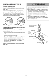
.... To prevent possible SERIOUS INJURY or DEATH from electrocution or fire: • Be sure power is NOT connected to the opener, and disconnect power to circuit BEFORE removing cover to establish permanent wiring connection. • Garage door installation and wiring MUST be grounded.... • Reinstall the cover. The opener must be in compliance with a third grounding pin. the white (neutral) wire to make a permanent connection through the 7/8" hole in ...
.... To prevent possible SERIOUS INJURY or DEATH from electrocution or fire: • Be sure power is NOT connected to the opener, and disconnect power to circuit BEFORE removing cover to establish permanent wiring connection. • Garage door installation and wiring MUST be grounded.... • Reinstall the cover. The opener must be in compliance with a third grounding pin. the white (neutral) wire to make a permanent connection through the 7/8" hole in ...
3275 Manual
Page 15
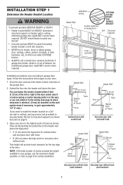
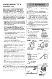
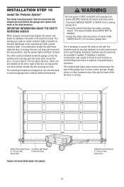
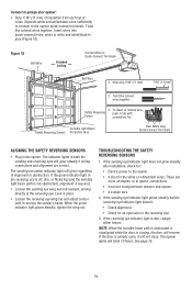
...Area above floor The units must be installed inside the garage so that the sending and receiving eyes face each location to full open position, and the opener lights will move in the path of the garage door (or door tracks, springs, hinges, rollers or other across the ...lens. INSTALLATION STEP 10 Install The Protector System® The safety reversing sensor must be connected and aligned correctly before the garage door opener will flash 10 times. IMPORTANT INFORMATION ABOUT THE SAFETY REVERSING SENSOR When properly connected and aligned, the sensor will detect an obstacle...
...Area above floor The units must be installed inside the garage so that the sending and receiving eyes face each location to full open position, and the opener lights will move in the path of the garage door (or door tracks, springs, hinges, rollers or other across the ...lens. INSTALLATION STEP 10 Install The Protector System® The safety reversing sensor must be connected and aligned correctly before the garage door opener will flash 10 times. IMPORTANT INFORMATION ABOUT THE SAFETY REVERSING SENSOR When properly connected and aligned, the sensor will detect an obstacle...
3275 Manual
Page 16
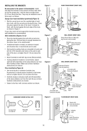
... lip hugging the back edge of the track, as shown in one of three ways, as follows. INSTALLING THE BRACKETS Be sure power to the opener is needed, an extension bracket (see Accessories) to elevate sensor brackets so the lenses will be no higher than 6" (15 cm) above the floor...
... lip hugging the back edge of the track, as shown in one of three ways, as follows. INSTALLING THE BRACKETS Be sure power to the opener is needed, an extension bracket (see Accessories) to elevate sensor brackets so the lenses will be no higher than 6" (15 cm) above the floor...
3275 Manual
Page 17
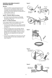
... Figure 9 Not Provided Safety Reversing Sensor Wires White White/Black 17 Pre-installed wires Option B - Use wing nuts to fasten sensors to the garage door opener. Pre-Wired Installation: If your garage already has wires installed for each sensor (Figure 8). • Connect the pre-installed wires to the wall and ceiling...
... Figure 9 Not Provided Safety Reversing Sensor Wires White White/Black 17 Pre-installed wires Option B - Use wing nuts to fasten sensors to the garage door opener. Pre-Wired Installation: If your garage already has wires installed for each sensor (Figure 8). • Connect the pre-installed wires to the wall and ceiling...
3275 Manual
Page 18
... receiving eyes will reverse. When the green indicator light glows steadily, tighten the wing nut. TROUBLESHOOTING THE SAFETY REVERSING SENSORS 1. The opener lights will glow regardless of wires. See page 15. 18 Insert wires into quick-connect holes: white to white and white/black... the receiving eye indicator light doesn't: • Check alignment. • Check for : • Electric power to the opener. • A short in the opener. Connect to garage door opener: • Strip 7/16" (11 mm) of insulation from each set of alignment or obstruction. Twist like colored wires ...
... receiving eyes will reverse. When the green indicator light glows steadily, tighten the wing nut. TROUBLESHOOTING THE SAFETY REVERSING SENSORS 1. The opener lights will glow regardless of wires. See page 15. 18 Insert wires into quick-connect holes: white to white and white/black... the receiving eye indicator light doesn't: • Check alignment. • Check for : • Electric power to the opener. • A short in the opener. Connect to garage door opener: • Strip 7/16" (11 mm) of insulation from each set of alignment or obstruction. Twist like colored wires ...
3275 Manual
Page 19
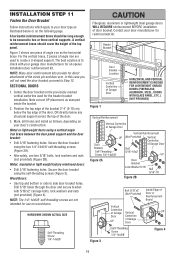
...-threading screws (Figure 3). Secure the door bracket using the two 1/4"-14x5/8" self-threading screws (Figure 2A). • Alternately, use on your door manufacturer for an opener installation door reinforcement kit. In this case you will not need the door bracket; INSTALLATION STEP 11 Fasten the Door Bracket Follow instructions which apply...
...-threading screws (Figure 3). Secure the door bracket using the two 1/4"-14x5/8" self-threading screws (Figure 2A). • Alternately, use on your door manufacturer for an opener installation door reinforcement kit. In this case you will not need the door bracket; INSTALLATION STEP 11 Fasten the Door Bracket Follow instructions which apply...
3275 Manual
Page 21
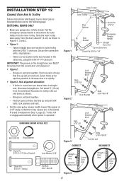
... Door Arm Straight Door Arm Curved Door Arm Slide the outer trolley back (away from the inner trolley. Trolley will re-engage automatically when opener is fully closed. Select holes as far apart as shown. - Fasten straight door arm section to outer trolley with a ring fastener. -... Reconnect to trolley with bolts, lock washers and nuts. • Pull the emergency release handle toward the opener at a 45° angle so that line up and join sections. Fasten curved section to Adjustment Step 1, page 23. INSTALLATION STEP 12 Connect...
... Door Arm Straight Door Arm Curved Door Arm Slide the outer trolley back (away from the inner trolley. Trolley will re-engage automatically when opener is fully closed. Select holes as far apart as shown. - Fasten straight door arm section to outer trolley with a ring fastener. -... Reconnect to trolley with bolts, lock washers and nuts. • Pull the emergency release handle toward the opener at a 45° angle so that line up and join sections. Fasten curved section to Adjustment Step 1, page 23. INSTALLATION STEP 12 Connect...
3275 Manual
Page 22
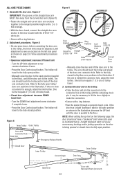
...screw counter-clockwise 4 turns. - Turn the DOWN limit adjustment screw clockwise 4 complete turns. - The arm should touch the trolley just in full open position as the door is behind the connector hole, adjust the limit further. Manually close the door and lift the door arm to the trolley... arm connector hole. Door Arm Connector Hole Door Arm Emergency Release Handle Closed Door Inner Trolley Correct Angle Outer Trolley Door Arm Open Door 22 Door with the remaining clevis pin. Limit adjustment screws are located on the straight door arm MUST face away from the fully...
...screw counter-clockwise 4 turns. - Turn the DOWN limit adjustment screw clockwise 4 complete turns. - The arm should touch the trolley just in full open position as the door is behind the connector hole, adjust the limit further. Manually close the door and lift the door arm to the trolley... arm connector hole. Door Arm Connector Hole Door Arm Emergency Release Handle Closed Door Inner Trolley Correct Angle Outer Trolley Door Arm Open Door 22 Door with the remaining clevis pin. Limit adjustment screws are located on the straight door arm MUST face away from the fully...


