3275 Manual
Page 2
... word review 2 Preparing your garage door 3 Tools needed 3 Planning 4 Carton inventory 5 Installation hardware 5 Assembly 6-7 Attach the rail to the motor unit 6 Attach the chain spreader 6 Tighten the chain 7 Installation 7-22 Installation safety instructions 7 Determine the header bracket location 8 Install the header...add, reprogram or change a Keyless Entry PIN 32 Repair Parts 33-34 Rail assembly parts 33 Installation parts 33 Motor unit assembly parts 34 Accessories 35 Repair Parts and Service 36 Warranty 36 INTRODUCTION Safety Symbol and Signal Word Review...
... word review 2 Preparing your garage door 3 Tools needed 3 Planning 4 Carton inventory 5 Installation hardware 5 Assembly 6-7 Attach the rail to the motor unit 6 Attach the chain spreader 6 Tighten the chain 7 Installation 7-22 Installation safety instructions 7 Determine the header bracket location 8 Install the header...add, reprogram or change a Keyless Entry PIN 32 Repair Parts 33-34 Rail assembly parts 33 Installation parts 33 Motor unit assembly parts 34 Accessories 35 Repair Parts and Service 36 Warranty 36 INTRODUCTION Safety Symbol and Signal Word Review...

3275 Manual
Page 4
...door must not exceed 1/4" (6 mm). Header Wall FINISHED CEILING Support bracket & fastening hardware is closed Extension Spring OR Torsion Spring Motor unit Vertical Centerline of Garage Door OR One-Piece Door-Extension Spring Wall-mounted Door Control Header Wall Access Door Door Track Safety Reversing...Slack in chain tension is normal when garage door is closed FINISHED CEILING Support bracket & fastening hardware is needed for details. Motor unit Wall-mounted Door Control ONE-PIECE DOOR WITH TRACK Slack in chain tension is normal when garage door is closed Access ...
...door must not exceed 1/4" (6 mm). Header Wall FINISHED CEILING Support bracket & fastening hardware is closed Extension Spring OR Torsion Spring Motor unit Vertical Centerline of Garage Door OR One-Piece Door-Extension Spring Wall-mounted Door Control Header Wall Access Door Door Track Safety Reversing...Slack in chain tension is normal when garage door is closed FINISHED CEILING Support bracket & fastening hardware is needed for details. Motor unit Wall-mounted Door Control ONE-PIECE DOOR WITH TRACK Slack in chain tension is normal when garage door is closed Access ...
3275 Manual
Page 5
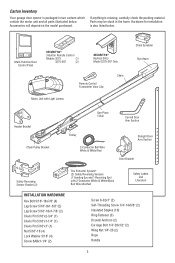
..., carefully check the packing material. Multi-Function Door Control Panel SECURITY✚® 3-Button Remote Control Models 3275 (1) 3275-267 (2) SECURITY✚® Keyless Entry Model 3275-267 Only Remote Control Transmitter Visor Clip Chain Motor Unit with Light Lenses Chain Spreader Styrofoam Header Bracket Chain Pulley Bracket One-Piece T-Rail Curved Door Arm...
..., carefully check the packing material. Multi-Function Door Control Panel SECURITY✚® 3-Button Remote Control Models 3275 (1) 3275-267 (2) SECURITY✚® Keyless Entry Model 3275-267 Only Remote Control Transmitter Visor Clip Chain Motor Unit with Light Lenses Chain Spreader Styrofoam Header Bracket Chain Pulley Bracket One-Piece T-Rail Curved Door Arm...
3275 Manual
Page 6
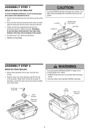
... opener: • ALWAYS keep hand clear of sprocket while operating opener. • Securely attach chain spreader BEFORE operating. ASSEMBLY STEP 1 Attach the Rail to the Motor Unit To avoid installation difficulties, do not run the garage door opener until instructed to do so. • Remove the bolt and lock... nut from the top of the motor unit. • Place rail onto the bolt mounted on the trolley to obtain more chain slack. Lock Nut T-Rail Hole Washered Bolt 5/16"-18x1/2" ...
... opener: • ALWAYS keep hand clear of sprocket while operating opener. • Securely attach chain spreader BEFORE operating. ASSEMBLY STEP 1 Attach the Rail to the Motor Unit To avoid installation difficulties, do not run the garage door opener until instructed to do so. • Remove the bolt and lock... nut from the top of the motor unit. • Place rail onto the bolt mounted on the trolley to obtain more chain slack. Lock Nut T-Rail Hole Washered Bolt 5/16"-18x1/2" ...
3275 Manual
Page 10
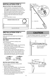
Slide the outer trolley toward the motor unit. Rail Door 2x4 is convenient for setting an ideal door-to-rail distance. • Remove foam packaging. • Raise the opener onto a stepladder. You ... to clear the spring. • Position the rail bracket against the header bracket. • Align the bracket holes and join with the top of the motor unit. Have someone hold the opener securely on the garage floor below the header bracket. NOTE: If the door spring is completed.
Slide the outer trolley toward the motor unit. Rail Door 2x4 is convenient for setting an ideal door-to-rail distance. • Remove foam packaging. • Raise the opener onto a stepladder. You ... to clear the spring. • Position the rail bracket against the header bracket. • Align the bracket holes and join with the top of the motor unit. Have someone hold the opener securely on the garage floor below the header bracket. NOTE: If the door spring is completed.
3275 Manual
Page 11
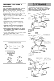
... 5/16"-18x1-7/8" lag screws. 5. NOTE: DO NOT connect power to the structural support. 2. Cut both pieces of the hanging bracket to structural supports of the motor unit to opener at this time. Yours may be used if installing ANY brackets into masonry. Attach one end of each side of the garage...
... 5/16"-18x1-7/8" lag screws. 5. NOTE: DO NOT connect power to the structural support. 2. Cut both pieces of the hanging bracket to structural supports of the motor unit to opener at this time. Yours may be used if installing ANY brackets into masonry. Attach one end of each side of the garage...
3275 Manual
Page 12
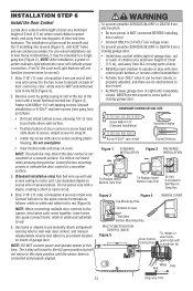
..., loosen the two mounting screws or relocate the door control to a smoother surface. 3. (Standard installation only) Run bell wire up wall and across ceiling to motor unit. Remove cover by color: white wire to WHT and white/red wire to secure wire in tab with 6ABx1-1/4" self-tapping screws (drywall installation...
..., loosen the two mounting screws or relocate the door control to a smoother surface. 3. (Standard installation only) Run bell wire up wall and across ceiling to motor unit. Remove cover by color: white wire to WHT and white/red wire to secure wire in tab with 6ABx1-1/4" self-tapping screws (drywall installation...
3275 Manual
Page 14
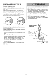
... with ALL local electrical and building codes. • NEVER use an extension cord, 2-wire adapter, or change plug in the top of the motor unit: • Remove the motor unit cover screws and set the cover aside. • Remove the attached 3-prong cord. • Connect the black (line) wire to the screw...
... with ALL local electrical and building codes. • NEVER use an extension cord, 2-wire adapter, or change plug in the top of the motor unit: • Remove the motor unit cover screws and set the cover aside. • Remove the attached 3-prong cord. • Connect the black (line) wire to the screw...
3275 Manual
Page 23
... UP (open door provides adequate clearance. Test the door for a trained door systems technician. If the door is adjusted, the other control may cause the motor to travel .
... UP (open door provides adequate clearance. Test the door for a trained door systems technician. If the door is adjusted, the other control may cause the motor to travel .
3275 Manual
Page 24
The maximum force adjustment range is about halfway through a complete travel (including binding or unbalanced doors), it will interfere with proper operation of the motor unit. Turn force adjustment controls with the door's downward travel cycle. If anything interferes with 1-1/2" high (3.8 cm) object (or 2x4 laid flat least 5 feet (1.5 m), ...
The maximum force adjustment range is about halfway through a complete travel (including binding or unbalanced doors), it will interfere with proper operation of the motor unit. Turn force adjustment controls with the door's downward travel cycle. If anything interferes with 1-1/2" high (3.8 cm) object (or 2x4 laid flat least 5 feet (1.5 m), ...
3275 Manual
Page 27
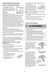
... Lock button again for 4-1/2 minutes. The door should be Trolley Release raised and lowered manually Arm as often as the Lock feature is on the motor unit panel is activated. To reconnect the door to 2-1/2 minutes. It will blink twice, resetting the timer to the Emergency opener, press the door control...
... Lock button again for 4-1/2 minutes. The door should be Trolley Release raised and lowered manually Arm as often as the Lock feature is on the motor unit panel is activated. To reconnect the door to 2-1/2 minutes. It will blink twice, resetting the timer to the Emergency opener, press the door control...
3275 Manual
Page 29
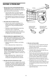
... it is blinking, deactivate the Lock Mode following page. 2. Decrease down travel . • Manually check door for flashes on my motor unit: The safety reversing sensor must be connected and aligned correctly before the garage door opener will sag. Using the Wall Mounted Door Control, Light...control is reconnected and closed position. • Loosen the chain by adjusting the outer nut 4 to Adjustment Step 2, Adjust the Force. 4. My motor unit hums briefly: • First verify that the trolley is normal.) • If the trolley does not move in particular can affect ...
... it is blinking, deactivate the Lock Mode following page. 2. Decrease down travel . • Manually check door for flashes on my motor unit: The safety reversing sensor must be connected and aligned correctly before the garage door opener will sag. Using the Wall Mounted Door Control, Light...control is reconnected and closed position. • Loosen the chain by adjusting the outer nut 4 to Adjustment Step 2, Adjust the Force. 4. My motor unit hums briefly: • First verify that the trolley is normal.) • If the trolley does not move in particular can affect ...
3275 Manual
Page 30
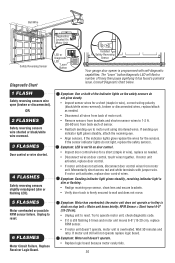
... reset. RPM Sensor = Short travel 6-8" (15-20 cm). • Unplug unit to reset. 6 FLASHES Motor Circuit Failure. Symptom: Motor unit doesn't operate. • Replace logic board because motor rarely fails. 30 Symptom: Sending indicator light glows steadily, receiving indicator light is dim or flashing. •...lens and secure brackets. • Verify door track is stuck on the safety sensors do not light, replace the safety sensors. Symptom: Motor has overheated; Wait 30 minutes and retry. OR 2 FLASHES Safety reversing sensors wire shorted or black/white wire reversed. 3 FLASHES Door...
... reset. RPM Sensor = Short travel 6-8" (15-20 cm). • Unplug unit to reset. 6 FLASHES Motor Circuit Failure. Symptom: Motor unit doesn't operate. • Replace logic board because motor rarely fails. 30 Symptom: Sending indicator light glows steadily, receiving indicator light is dim or flashing. •...lens and secure brackets. • Verify door track is stuck on the safety sensors do not light, replace the safety sensors. Symptom: Motor has overheated; Wait 30 minutes and retry. OR 2 FLASHES Safety reversing sensors wire shorted or black/white wire reversed. 3 FLASHES Door...
3275 Manual
Page 31
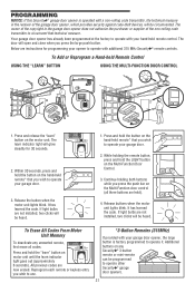
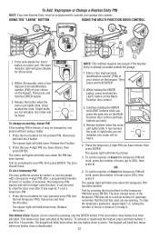
...the hand-held ). 4. Press and release the "learn" button on motor unit until the learn indicator light goes out (approximately 6 seconds). Release buttons when the motor unit lights blink. To Erase All Codes From Motor Unit Memory To deactivate any Security✚® 3-button remote or mini...holding the remote button, press and hold the "learn indicator light will be circumvented. The learn " button on the motor unit. Release the button when the motor unit lights blink. The owner of the copyright in the receiver of the non-rolling code transmitter to circumvent that you...
...the hand-held ). 4. Press and release the "learn" button on motor unit until the learn indicator light goes out (approximately 6 seconds). Release buttons when the motor unit lights blink. To Erase All Codes From Motor Unit Memory To deactivate any Security✚® 3-button remote or mini...holding the remote button, press and hold the "learn indicator light will be circumvented. The learn " button on the motor unit. Release the button when the motor unit lights blink. The owner of the copyright in the receiver of the non-rolling code transmitter to circumvent that you...
3275 Manual
Page 32
...visitors or service people with a temporary 4-digit PIN. Within 30 seconds, enter a four digit personal identification number (PIN) of your choice on motor unit. Release the # button. 2. The door should move . NOTE: This method requires two people if the Keyless Entry is known, it has expired...), then press and hold the ENTER button. 3. Then press and hold buttons 1 and 9 for your garage door opener. Release buttons when the motor unit lights blink. Press the four buttons for 10 seconds. Press the new 4-digit PIN you have chosen, then press ENTER. The opener light...
...visitors or service people with a temporary 4-digit PIN. Within 30 seconds, enter a four digit personal identification number (PIN) of your choice on motor unit. Release the # button. 2. The door should move . NOTE: This method requires two people if the Keyless Entry is known, it has expired...), then press and hold the ENTER button. 3. Then press and hold buttons 1 and 9 for your garage door opener. Release buttons when the motor unit lights blink. Press the four buttons for 10 seconds. Press the new 4-digit PIN you have chosen, then press ENTER. The opener light...
3275 Manual
Page 34
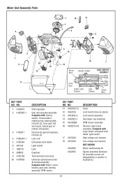
..., bracket, gear case, bearing assembly, RPM sensor KEY PART NO. Motor Unit Assembly Parts 6 1 18 2 3 4 17 6 5 7 8 10 12 13 11 9 15 16 14 Brown Wire (Down) Contact 7 LIMIT SWITCH ASSEMBLY Drive Gear Center Limit Contact (Up) ... w/ retainer and grease Drive/worm gear kit w/grease, roll pins (2) Line cord End panels w/all labels Light socket Lens Capacitor Terminal block w/screws Universal replacement motor & bracket assembly Complete with : Logic board, end panel w/all labels, light socket High voltage wire harness Low voltage wire harness NOT SHOWN...
..., bracket, gear case, bearing assembly, RPM sensor KEY PART NO. Motor Unit Assembly Parts 6 1 18 2 3 4 17 6 5 7 8 10 12 13 11 9 15 16 14 Brown Wire (Down) Contact 7 LIMIT SWITCH ASSEMBLY Drive Gear Center Limit Contact (Up) ... w/ retainer and grease Drive/worm gear kit w/grease, roll pins (2) Line cord End panels w/all labels Light socket Lens Capacitor Terminal block w/screws Universal replacement motor & bracket assembly Complete with : Logic board, end panel w/all labels, light socket High voltage wire harness Low voltage wire harness NOT SHOWN...
3275 Manual
Page 36
... gives you specific legal rights, and you will be defective and covered by Seller are confirmed to you . LIFTMASTER® SERVICE IS ON CALL OUR LARGE SERVICE ORGANIZATION SPANS AMERICA INSTALLATION AND SERVICE INFORMATION IS AS NEAR AS YOUR TELEPHONE. SIMPLY ... dealer. Technical Support Group 6050 S. Country Club Road Tucson, Arizona 85706 SERVICE INFORMATION TOLL FREE NUMBER: 1-800-528-9131 LIFTMASTER ONE-YEAR LIMITED WARRANTY LIFETIME MOTOR LIMITED WARRANTY The Chamberlain Group, Inc. ("Seller") warrants to the first retail purchaser of dealers in the Yellow Pages,...
... gives you specific legal rights, and you will be defective and covered by Seller are confirmed to you . LIFTMASTER® SERVICE IS ON CALL OUR LARGE SERVICE ORGANIZATION SPANS AMERICA INSTALLATION AND SERVICE INFORMATION IS AS NEAR AS YOUR TELEPHONE. SIMPLY ... dealer. Technical Support Group 6050 S. Country Club Road Tucson, Arizona 85706 SERVICE INFORMATION TOLL FREE NUMBER: 1-800-528-9131 LIFTMASTER ONE-YEAR LIMITED WARRANTY LIFETIME MOTOR LIMITED WARRANTY The Chamberlain Group, Inc. ("Seller") warrants to the first retail purchaser of dealers in the Yellow Pages,...


