
X4500, X7500 MFP Options User's Guide
Page 51
... scan. 5 Assign a Profile Name. For complete installation instructions, refer to the document included on the screens to define your computer. Your scan file is installed on your computer. 1 From your computer, launch the ScanBack utility. 2 Select the MFP you want to your original document and the type... of the profile you set up from your MFP. The following instructions assume ScanBack is saved...
... scan. 5 Assign a Profile Name. For complete installation instructions, refer to the document included on the screens to define your computer. Your scan file is installed on your computer. 1 From your computer, launch the ScanBack utility. 2 Select the MFP you want to your original document and the type... of the profile you set up from your MFP. The following instructions assume ScanBack is saved...

Setup Guide
Page 5
Step 1: Set up your printer 1 Modifying your high capacity feeder or base cabinet 1 Selecting a location for your MFP 3 Step 2: Set up the scanner stand 4 Unpacking the stand 4 Assembling the stand 5 Step 3: Install the control unit 6 Step 4: Mount the power supply 8 Step 5: Attach the stand to the printer 9 Attaching the optional finisher 9 Step 6: Install the scanner 10 Unpacking the scanner 10 Installing the scanner 10 v
Step 1: Set up your printer 1 Modifying your high capacity feeder or base cabinet 1 Selecting a location for your MFP 3 Step 2: Set up the scanner stand 4 Unpacking the stand 4 Assembling the stand 5 Step 3: Install the control unit 6 Step 4: Mount the power supply 8 Step 5: Attach the stand to the printer 9 Attaching the optional finisher 9 Step 6: Install the scanner 10 Unpacking the scanner 10 Installing the scanner 10 v
Setup Guide
Page 6
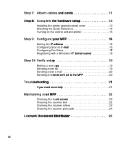
Step 7: Attach cables and cords 11 Step 8: Complete the hardware setup 13 Installing the printer operator panel cover 13 Attaching the Quick Reference 14 Turning on the control unit and printer 15 Step 9: Configure your MFP 16 Setting the IP address 16 Configuring Scan to E-mail 16 Configuring Fax ... copy 19 Sending a test fax 19 Sending a test e-mail 20 Sending a network print job to the MFP 20 Troubleshooting 21 If you need more help 21 Maintaining your MFP 22 Cleaning the touch screen 22 Cleaning the scanner bed 22 Cleaning the scanner rollers 22 Cleaning the scanner pick...
Step 7: Attach cables and cords 11 Step 8: Complete the hardware setup 13 Installing the printer operator panel cover 13 Attaching the Quick Reference 14 Turning on the control unit and printer 15 Step 9: Configure your MFP 16 Setting the IP address 16 Configuring Scan to E-mail 16 Configuring Fax ... copy 19 Sending a test fax 19 Sending a test e-mail 20 Sending a network print job to the MFP 20 Troubleshooting 21 If you need more help 21 Maintaining your MFP 22 Cleaning the touch screen 22 Cleaning the scanner bed 22 Cleaning the scanner rollers 22 Cleaning the scanner pick...

Setup Guide
Page 9
...Modifying your printer yet, unpack the high capacity feeder or base cabinet and remove any foam and tape from inside. You need to repack the option later. Save the carton and packing materials if you need a Phillips screwdriver to do this. Whether you have a printer that you need to...publications CD for your printer, you need to modify your printer 1 You need one of these options for information on how to modify and install the high capacity feeder. If you have an installed printer, you need to fit properly into the stand. Set up your high capacity feeder or ...
...Modifying your printer yet, unpack the high capacity feeder or base cabinet and remove any foam and tape from inside. You need to repack the option later. Save the carton and packing materials if you need a Phillips screwdriver to do this. Whether you have a printer that you need to...publications CD for your printer, you need to modify your printer 1 You need one of these options for information on how to modify and install the high capacity feeder. If you have an installed printer, you need to fit properly into the stand. Set up your high capacity feeder or ...
Setup Guide
Page 10
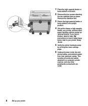
... menu settings page. 6 Unplug all cords and cables attached to a computer, printer, scanner, and any other paper handling options except an optional finisher. 1 Place the high capacity feeder or base cabinet on how to install these items, refer to your printer If you have a finisher, attach it later. This includes all power cords...
... menu settings page. 6 Unplug all cords and cables attached to a computer, printer, scanner, and any other paper handling options except an optional finisher. 1 Place the high capacity feeder or base cabinet on how to install these items, refer to your printer If you have a finisher, attach it later. This includes all power cords...

Setup Guide
Page 14
...-11) e Ethernet cable (RJ-45) (with toroid) f Operator panel housing g Power switch cover h Operator panel cover i Folder with Setup Guide, MFP CD, and a set of Quick References (in different languages) j Power supply line cord k Two nuts and bolts The box may also contain an adapter... for telephone fax line cable (not shown). 6 Install the control unit a: Control unit h: Operator panel cover i: Folder g: Power switch cover j: Power supply line cord f: Operator panel housing c: Power supply...
...-11) e Ethernet cable (RJ-45) (with toroid) f Operator panel housing g Power switch cover h Operator panel cover i Folder with Setup Guide, MFP CD, and a set of Quick References (in different languages) j Power supply line cord k Two nuts and bolts The box may also contain an adapter... for telephone fax line cable (not shown). 6 Install the control unit a: Control unit h: Operator panel cover i: Folder g: Power switch cover j: Power supply line cord f: Operator panel housing c: Power supply...

Setup Guide
Page 15
... saved in easily, loosen the screws on the top and bottom. 4 Slide the unit between the stand legs. Leave the top two screws slightly loose. Install the control unit 7 Align the holes on the mounting tabs with the holes on the stand beam and the base. 5 Attach the control unit to... the stand with the four screws you install the control unit retighten these screws. 2 Move to the back of the stand. 3 Hold the control unit so the cable connection ports are toward the...
... saved in easily, loosen the screws on the top and bottom. 4 Slide the unit between the stand legs. Leave the top two screws slightly loose. Install the control unit 7 Align the holes on the mounting tabs with the holes on the stand beam and the base. 5 Attach the control unit to... the stand with the four screws you install the control unit retighten these screws. 2 Move to the back of the stand. 3 Hold the control unit so the cable connection ports are toward the...

Setup Guide
Page 18
Scanner - Align the handholds on the scanner with toroid) Save the packing material until the system is turned off and unplugged. 2 Place the scanner on the shelf. 10 Install the scanner Toroid Installing the scanner 1 Make sure the printer is completely set up and working correctly. Scanner cable (with the cutouts on the shelf. Unpacking the scanner Unpack the MFP scanner. Make sure you have the following items: -
Scanner - Align the handholds on the scanner with toroid) Save the packing material until the system is turned off and unplugged. 2 Place the scanner on the shelf. 10 Install the scanner Toroid Installing the scanner 1 Make sure the printer is completely set up and working correctly. Scanner cable (with the cutouts on the shelf. Unpacking the scanner Unpack the MFP scanner. Make sure you have the following items: -
Setup Guide
Page 21
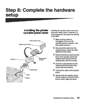
...Leave the cable attached to the printer. 3 Remove the three screws from the back of the MFP. 1 Make sure the printer is optional. Complete the hardware setup 13 Housing Installing the printer operator panel cover Power switch cover Operator panel cover Replacement housing Subassembly Cable Recess... Installing the operator panel cover and the power switch cover is unplugged. It is not ...
...Leave the cable attached to the printer. 3 Remove the three screws from the back of the MFP. 1 Make sure the printer is optional. Complete the hardware setup 13 Housing Installing the printer operator panel cover Power switch cover Operator panel cover Replacement housing Subassembly Cable Recess... Installing the operator panel cover and the power switch cover is unplugged. It is not ...

Setup Guide
Page 23
... touch screen. During this period, the message Please wait while the device initializes appears on the touch screen. Complete the hardware setup 15 The MFP requires time to warm up after you turn it on the control unit. Turning on the control unit and printer 1 Plug the printer and... the power supply line cord into properly grounded electrical outlets. 2 Turn the printer on. 3 Install the power switch cover (see "Installing the printer operator panel cover" on page 13 for illustration): a Slide the locking tabs on the bottom of the cover into the ...
... touch screen. During this period, the message Please wait while the device initializes appears on the touch screen. Complete the hardware setup 15 The MFP requires time to warm up after you turn it on the control unit. Turning on the control unit and printer 1 Plug the printer and... the power supply line cord into properly grounded electrical outlets. 2 Turn the printer on. 3 Install the power switch cover (see "Installing the printer operator panel cover" on page 13 for illustration): a Slide the locking tabs on the bottom of the cover into the ...

Setup Guide
Page 32
... left groove. 8 Tilt the roller plate up and slanted slightly down on the right side. 9 Slide the plate back until it snaps into place. 10 Install the two screws to the printer publications CD. 24 Maintaining your...
... left groove. 8 Tilt the roller plate up and slanted slightly down on the right side. 9 Slide the plate back until it snaps into place. 10 Install the two screws to the printer publications CD. 24 Maintaining your...

Setup Guide
Page 34
... guide during a lightning storm. • Never install or use this symbol , it MUST be connected to an electrical outlet that is properly grounded. • The power cord must be obvious. Emission notices The following : • If your MFP system hardware or software. The safety features of...responsible for the use of specific Lexmark components. A caution identifies something that might damage your product is NOT marked with the use of other than those machines in which the 4036- 501(scanner) and/or 4036-901(control unit) is installed. 26 Notices Cautions and warnings CAUTION...
... guide during a lightning storm. • Never install or use this symbol , it MUST be connected to an electrical outlet that is properly grounded. • The power cord must be obvious. Emission notices The following : • If your MFP system hardware or software. The safety features of...responsible for the use of specific Lexmark components. A caution identifies something that might damage your product is NOT marked with the use of other than those machines in which the 4036- 501(scanner) and/or 4036-901(control unit) is installed. 26 Notices Cautions and warnings CAUTION...

Setup Guide
Page 35
...Canada. Operation is subject to operate this equipment. This equipment generates, uses, and can radiate radio frequency energy and, if not installed and used in accordance with the instruction manual, may not cause harmful interference, and (2) this equipment in a residential area is operated... changes or modifications to radio communications. Operation of electrical equipment designed for use a properly shielded and grounded cable such as Lexmark part number 1329605. Note: To assure compliance with FCC regulations on the approximation and harmonization of the laws of the Member...
...Canada. Operation is subject to operate this equipment. This equipment generates, uses, and can radiate radio frequency energy and, if not installed and used in accordance with the instruction manual, may not cause harmful interference, and (2) this equipment in a residential area is operated... changes or modifications to radio communications. Operation of electrical equipment designed for use a properly shielded and grounded cable such as Lexmark part number 1329605. Note: To assure compliance with FCC regulations on the approximation and harmonization of the laws of the Member...
Setup Guide
Page 37
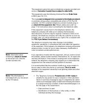
...surges. • The Telephone Consumer Protection Act of service may request you believe it is resolved. It is recommended that the customer install an ac surge arrestor in advance that could affect the operation of the business or other entity, or other electronic device to disconnect ... is located on page 11 for you will notify you cannot correct the problem, please contact Lexmark International, Inc. This is designed to be used on the first page of a telephone fax option unless such message clearly contains the following Universal Service Order Code (USOC) jack: RJ-11C....
...surges. • The Telephone Consumer Protection Act of service may request you believe it is resolved. It is recommended that the customer install an ac surge arrestor in advance that could affect the operation of the business or other entity, or other electronic device to disconnect ... is located on page 11 for you will notify you cannot correct the problem, please contact Lexmark International, Inc. This is designed to be used on the first page of a telephone fax option unless such message clearly contains the following Universal Service Order Code (USOC) jack: RJ-11C....
Setup Guide
Page 38
CAUTION! This equipment uses the following Jacks: CA11A. Before installing this equipment, users should ensure for pan-European 30 Notices Repairs to the facilities of the local telecommunications company. Users should ensure that it ...number of all the devices does not exceed 5. The Department does not guarantee the equipment will operate to a telephone interface. The customer should be installed using an acceptable method of the sending machine or such business, other entity, or individual Industry Canada CS03 Notice The Industry Canada label identifies certified...
CAUTION! This equipment uses the following Jacks: CA11A. Before installing this equipment, users should ensure for pan-European 30 Notices Repairs to the facilities of the local telecommunications company. Users should ensure that it ...number of all the devices does not exceed 5. The Department does not guarantee the equipment will operate to a telephone interface. The customer should be installed using an acceptable method of the sending machine or such business, other entity, or individual Industry Canada CS03 Notice The Industry Canada label identifies certified...

Setup Guide
Page 39
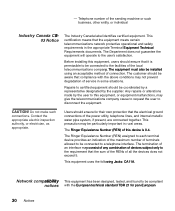
... Finland Luxemburg Netherlands Ireland Italy United Kingdom Switzerland Using the X820e MFP X7500 Option in Germany The X820e MFP/X7500 Option requires a German billing tone filter (P/N 14B5123) to inter-work with PSTN networks that metering pulses be installed on every PSTN network termination point. Using the X820e MFP X7500 Option in German. However, due to differences between the individual PSTNs...
... Finland Luxemburg Netherlands Ireland Italy United Kingdom Switzerland Using the X820e MFP X7500 Option in Germany The X820e MFP/X7500 Option requires a German billing tone filter (P/N 14B5123) to inter-work with PSTN networks that metering pulses be installed on every PSTN network termination point. Using the X820e MFP X7500 Option in German. However, due to differences between the individual PSTNs...

Service Manual
Page 10
... illustrations and part numbers for making scanner adjustments and removing and installing FRUs. 5. Diagnostic Information contains error indicator tables, and troubleshooting tables used to prevent problems. 7. Repair Information provides instructions for individual FRUs. 4036-501 Preface This manual describes the Lexmark X7500 Scanner (4036-501) and contains maintenance procedures for service personnel only...
... illustrations and part numbers for making scanner adjustments and removing and installing FRUs. 5. Diagnostic Information contains error indicator tables, and troubleshooting tables used to prevent problems. 7. Repair Information provides instructions for individual FRUs. 4036-501 Preface This manual describes the Lexmark X7500 Scanner (4036-501) and contains maintenance procedures for service personnel only...

Service Manual
Page 48
...the carriage guides with isopropyl alcohol. 2-8 Service Manual 4036-501 Strange sound generated (DADF) Cause Paper setting failure Paper failure ADF pick roller improperly installed Motor assembly failure Gear failure Main drive motor assembly Dirt on carriage guides Relevant unit Operation error Operation error Pick roller assembly • DADF registration... rotation. Visual check of pick roller. Main drive assembly Check method Is the paper correctly set in the upper paper guide? None Re-install pick roller assembly. Replace the motor. Replace the failure motor assembly.
...the carriage guides with isopropyl alcohol. 2-8 Service Manual 4036-501 Strange sound generated (DADF) Cause Paper setting failure Paper failure ADF pick roller improperly installed Motor assembly failure Gear failure Main drive motor assembly Dirt on carriage guides Relevant unit Operation error Operation error Pick roller assembly • DADF registration... rotation. Visual check of pick roller. Main drive assembly Check method Is the paper correctly set in the upper paper guide? None Re-install pick roller assembly. Replace the motor. Replace the failure motor assembly.
Service Manual
Page 62
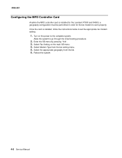
...-501 Configuring the MFD Controller Card Anytime the MFD controller card is installed, follow the instructions below to set the appropriate fax modem setting. 1. Select Fax Setting on the power to the complete system. Once the card is installed for the Lexmark X7500 and X4500, a geography configuration must be performed in order for the...
...-501 Configuring the MFD Controller Card Anytime the MFD controller card is installed, follow the instructions below to set the appropriate fax modem setting. 1. Select Fax Setting on the power to the complete system. Once the card is installed for the Lexmark X7500 and X4500, a geography configuration must be performed in order for the...

Service Manual
Page 64
4036-501 Note: Follow the steps in the order shown to install the DADF. 4-10 Service Manual
4036-501 Note: Follow the steps in the order shown to install the DADF. 4-10 Service Manual


