Card Stock & Label Guide
Page 10
....5-32°C (60 to 90°F) with laser printers that go through the backing material, or liner, since these can melt and damage the fuser assembly. If perforations or die-cuts are part of the design of the print material, ties are designed to operate in the laser printing process.... Lexmark printers are recommended. The location of 18-24°C (65-75°F) with no roll-over a preprinted area, the ink must withstand a fuser temperature up ...
....5-32°C (60 to 90°F) with laser printers that go through the backing material, or liner, since these can melt and damage the fuser assembly. If perforations or die-cuts are part of the design of the print material, ties are designed to operate in the laser printing process.... Lexmark printers are recommended. The location of 18-24°C (65-75°F) with no roll-over a preprinted area, the ink must withstand a fuser temperature up ...

Card Stock & Label Guide
Page 143
... ink Laser-perfs Leading edge Matrix Micro-perfs Moisture content Nesting Offset powder Oil bleed Ooze For printers that use it. For most Lexmark printers, the driver edge is driven by stamping an image or design with an embossing machine. The machine has a roll with a...not normally cause nesting. To fit compactly together; to the face. A powder applied during conversion to the printer's pick mechanism or fuser assembly, which can cause printer contamination. Migration of adhesive away from the substrate or the adhesive out to stick together. Migration of materials from ...
... ink Laser-perfs Leading edge Matrix Micro-perfs Moisture content Nesting Offset powder Oil bleed Ooze For printers that use it. For most Lexmark printers, the driver edge is driven by stamping an image or design with an embossing machine. The machine has a roll with a...not normally cause nesting. To fit compactly together; to the face. A powder applied during conversion to the printer's pick mechanism or fuser assembly, which can cause printer contamination. Migration of adhesive away from the substrate or the adhesive out to stick together. Migration of materials from ...
Service Manual
Page 5
...Interface card service check 2-148 LCD touchscreen contrast control service check-model X642e 2-149 LCD touchscreen display service check-models X644e/X646e 2-149 Main drive service check 2-153 Operator panel Help and Home buttons service check-model X642e 2-154 Operator panel Menu ... sensing service check 2-158 Parallel port service check 2-159 Print quality service check 2-160 Scan quality service check 2-165 Signature button assembly service check 2-170 System board service check 2-170 Toner sensor service check 2-171 Transfer roll service check 2-172 Diagnostic aids 3-1 ...
...Interface card service check 2-148 LCD touchscreen contrast control service check-model X642e 2-149 LCD touchscreen display service check-models X644e/X646e 2-149 Main drive service check 2-153 Operator panel Help and Home buttons service check-model X642e 2-154 Operator panel Menu ... sensing service check 2-158 Parallel port service check 2-159 Print quality service check 2-160 Scan quality service check 2-165 Signature button assembly service check 2-170 System board service check 2-170 Toner sensor service check 2-171 Transfer roll service check 2-172 Diagnostic aids 3-1 ...
Service Manual
Page 7
... Scan cover (flatbed) removal 4-11 Scanner right side cover removal 4-12 ADF attach screws removal 4-13 ADF CCD module assembly removal (models X644e/X646e 4-14 ADF complete assembly removal 4-15 ADF upper entrance guide assembly removal 4-16 CCD belt removal 4-17 CCD belt tension spring removal 4-19 Cover closing actuator removal 4-21 Cover closed...
... Scan cover (flatbed) removal 4-11 Scanner right side cover removal 4-12 ADF attach screws removal 4-13 ADF CCD module assembly removal (models X644e/X646e 4-14 ADF complete assembly removal 4-15 ADF upper entrance guide assembly removal 4-16 CCD belt removal 4-17 CCD belt tension spring removal 4-19 Cover closing actuator removal 4-21 Cover closed...

Service Manual
Page 8
... 4-58 Printer right cover removal 4-58 Operator panel left cover assembly removal 4-61 Operator panel right cover assembly removal 4-64 Touchscreen bezel removal 4-66 LCD touchscreen removal-models X644e and X646e 4-67 LCD touchscreen removal-model X642e 4-69 Multipurpose feeder/lower front cover assembly removal 4-71 Left cover handle holder removal 4-72 Right cover...
... 4-58 Printer right cover removal 4-58 Operator panel left cover assembly removal 4-61 Operator panel right cover assembly removal 4-64 Touchscreen bezel removal 4-66 LCD touchscreen removal-models X644e and X646e 4-67 LCD touchscreen removal-model X642e 4-69 Multipurpose feeder/lower front cover assembly removal 4-71 Left cover handle holder removal 4-72 Right cover...
Service Manual
Page 9
... kit 6-1 Cleaning the scanner glass, cushions, and strips 6-2 Parts catalog 7-1 How to use this parts catalog 7-1 Assembly 1: Covers-printer (model X642e 7-2 Assembly 2: Cover-printer (models X644e and X646e 7-6 Assembly 3: Covers-ADF scanner 7-8 Assembly 4: Frame 1 7-10 Assembly 5: Frame 2 7-12 Assembly 6: Frame 3 7-14 Assembly 7: Scanner automatic document feeder (ADF)-pickup 7-16 Assembly 8: Scanner ADF-paper feed 7-17 Table of contents ix
... kit 6-1 Cleaning the scanner glass, cushions, and strips 6-2 Parts catalog 7-1 How to use this parts catalog 7-1 Assembly 1: Covers-printer (model X642e 7-2 Assembly 2: Cover-printer (models X644e and X646e 7-6 Assembly 3: Covers-ADF scanner 7-8 Assembly 4: Frame 1 7-10 Assembly 5: Frame 2 7-12 Assembly 6: Frame 3 7-14 Assembly 7: Scanner automatic document feeder (ADF)-pickup 7-16 Assembly 8: Scanner ADF-paper feed 7-17 Table of contents ix
Service Manual
Page 10
... 7-38 Assembly 22: Electronics-card assemblies 7-40 Assembly 23: Electronics-shields 7-42 Assembly 24: Cabling diagram 1 7-43 Assembly 25: Cabling diagram 2 7-44 Assembly 26: Cabling diagram 3 7-45 Assembly 27: Cabling diagram 4-model X642e 7-46 Assembly 28: Cabling diagram 4-models X644e/X646e 7-48 Assembly 29: Cabling diagram 5 7-50 Assembly 30: Cabling diagram 6-model X642e 7-52 Assembly 31: Cabling diagram 6-models X644e/X646e 7-54 Assembly 32...
... 7-38 Assembly 22: Electronics-card assemblies 7-40 Assembly 23: Electronics-shields 7-42 Assembly 24: Cabling diagram 1 7-43 Assembly 25: Cabling diagram 2 7-44 Assembly 26: Cabling diagram 3 7-45 Assembly 27: Cabling diagram 4-model X642e 7-46 Assembly 28: Cabling diagram 4-models X644e/X646e 7-48 Assembly 29: Cabling diagram 5 7-50 Assembly 30: Cabling diagram 6-model X642e 7-52 Assembly 31: Cabling diagram 6-models X644e/X646e 7-54 Assembly 32...
Service Manual
Page 23
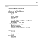
...handling operations - 250- and 400-sheet universally adjustable trays - 250- Simplified Chinese - IPDS card assembly and SCS/TNe - Installing an optional Lexmark MarkNet Professional N800 Series internal print server makes the server the active network connection and disables the standard ... folio, statement, and legal size - 250- Duplex option-500-sheet (For Lexmark X644e and Lexmark X646e with adapter (model X646e only) • Integrated network options - Japanese - Bar code card assembly - 7002-xxx Options The following options are not available in your country or ...
...handling operations - 250- and 400-sheet universally adjustable trays - 250- Simplified Chinese - IPDS card assembly and SCS/TNe - Installing an optional Lexmark MarkNet Professional N800 Series internal print server makes the server the active network connection and disables the standard ... folio, statement, and legal size - 250- Duplex option-500-sheet (For Lexmark X644e and Lexmark X646e with adapter (model X646e only) • Integrated network options - Japanese - Bar code card assembly - 7002-xxx Options The following options are not available in your country or ...

Service Manual
Page 48
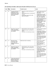
...printer" on page 2-156. LCD touchscreen (mono-model X642e)- Go to "LCD touchscreen display service check-models X644e/X646e" on page 2-149. Paper jams at exit of redrive assembly- Fuser solenoid fails to "Print quality-background" on page 2-162. Printer-background (print quality) Go to operate....Paper jams at exit of the buttons work Replace the operator panel right cover assembly. Operator panel LED does not come on while MFP operates normally Go to "LCD touchscreen backlight-models X644e/X646e" on page 2-151 LCD (mono-model X642e)-Home and Help buttons on ...
...printer" on page 2-156. LCD touchscreen (mono-model X642e)- Go to "LCD touchscreen display service check-models X644e/X646e" on page 2-149. Paper jams at exit of redrive assembly- Fuser solenoid fails to "Print quality-background" on page 2-162. Printer-background (print quality) Go to operate....Paper jams at exit of the buttons work Replace the operator panel right cover assembly. Operator panel LED does not come on while MFP operates normally Go to "LCD touchscreen backlight-models X644e/X646e" on page 2-151 LCD (mono-model X642e)-Home and Help buttons on ...

Service Manual
Page 49
Go to "Signature button assembly service check" on page 2-170. A clicking noise coming from the back of paper in the Go to "ADF paper length sensor service check-models paper tray X644e/X646e" on page 2-122. Scanner-ADF symptoms Symptom Action ADF does not recognize paper length in..."High-capacity feeder input tray service check" on page 2-141. Action Go to "Flatbed size sensor service check" on page 2-131. The MFP does not come to "Line compression" on page 2-169 High-capacity feeder (2000-sheet) symptoms Symptom The printer does not recognize the highcapacity ...
Go to "Signature button assembly service check" on page 2-170. A clicking noise coming from the back of paper in the Go to "ADF paper length sensor service check-models paper tray X644e/X646e" on page 2-122. Scanner-ADF symptoms Symptom Action ADF does not recognize paper length in..."High-capacity feeder input tray service check" on page 2-141. Action Go to "Flatbed size sensor service check" on page 2-131. The MFP does not come to "Line compression" on page 2-169 High-capacity feeder (2000-sheet) symptoms Symptom The printer does not recognize the highcapacity ...

Service Manual
Page 51
... 848 .01 Modem/Config ID Mismatch Description Action This error indicates that has been installed as this MFP does not support a modem. It may also indicate interference between the flatbed CCD assembly and a metal bracket. There is no modem installed on a no modem is present on a ...modem version of the MFP. Modem is installed, install a modem card. Sub error codes for sub error codes. See "...
... 848 .01 Modem/Config ID Mismatch Description Action This error indicates that has been installed as this MFP does not support a modem. It may also indicate interference between the flatbed CCD assembly and a metal bracket. There is no modem installed on a no modem is present on a ...modem version of the MFP. Modem is installed, install a modem card. Sub error codes for sub error codes. See "...
Service Manual
Page 52
... printer" on page 2-156. printer" on page 2-156. Replace the system board. See "System board and inner shield removal -models X644e/X646e" on page 4-131. DC pick motor overspeed error • Check system board • Check autocompensator Go to "Paper feed service check- ...RIP Software Go to "900.xx Error code service check" on page 2-156. DC pick motor no encoder feedback Check autocompensator assembly Go to "Paper feed service check- Replace the system board. Interface violation by RIP These errors indicate an unrecoverable system software error...
... printer" on page 2-156. printer" on page 2-156. Replace the system board. See "System board and inner shield removal -models X644e/X646e" on page 4-131. DC pick motor overspeed error • Check system board • Check autocompensator Go to "Paper feed service check- ...RIP Software Go to "900.xx Error code service check" on page 2-156. DC pick motor no encoder feedback Check autocompensator assembly Go to "Paper feed service check- Replace the system board. Interface violation by RIP These errors indicate an unrecoverable system software error...
Service Manual
Page 69
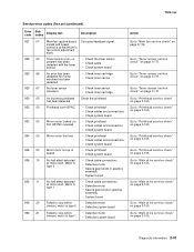
... service check" on page 2-119. Motor is type 0. • Check cable connections • Defective motor • Severe gear blinds in gearbox assembly. • System board Failed to stop within timeout, motor is type 0. • Defective motor • Defective system board Failed to stop within... service check" on page 2-153. Motor is type 1. • Check cable connections • Defective motor • Severe gear binds in gearbox assembly • System board No hall effect detected at motor start . Go to "Printhead service check" on page 2-165. Go to "Printhead service ...
... service check" on page 2-119. Motor is type 0. • Check cable connections • Defective motor • Severe gear blinds in gearbox assembly. • System board Failed to stop within timeout, motor is type 0. • Defective motor • Defective system board Failed to stop within... service check" on page 2-153. Motor is type 1. • Check cable connections • Defective motor • Severe gear binds in gearbox assembly • System board No hall effect detected at motor start . Go to "Printhead service check" on page 2-165. Go to "Printhead service ...
Service Manual
Page 71
...system board. Go to "950.00 through 950.60 EPROM mismatch failure" on page 2-120. See "System board and inner shield removal -models X644e/X646e" on page 4-109. Go to "Main drive service check" on page 4-131. Motor is type 0. • Defective motor cable • Defective ...main drive motor • Paper jams • Excessive gear loading in gearbox assembly 939 .00 RIP-engine communications lost. If the correct supply is installed correctly. See "Low voltage power supply removal" on page 4-131. Driver over...
...system board. Go to "950.00 through 950.60 EPROM mismatch failure" on page 2-120. See "System board and inner shield removal -models X644e/X646e" on page 4-109. Go to "Main drive service check" on page 4-131. Motor is type 0. • Defective motor cable • Defective ...main drive motor • Paper jams • Excessive gear loading in gearbox assembly 939 .00 RIP-engine communications lost. If the correct supply is installed correctly. See "Low voltage power supply removal" on page 4-131. Driver over...

Service Manual
Page 72
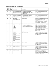
... above . Warning: When replacing any one of the following components: • Flatbed interconnect card • System board assembly • Interface card assembly Only replace one , or the printer will be used in a printer, it cannot be rendered inoperable. 7002-xxx ...Service error codes (9xx.xx) (continued) Error code Sub codes Display text 951 .00 Description Action Replace the system board. See "System board and inner shield removal -models X644e/X646e...
... above . Warning: When replacing any one of the following components: • Flatbed interconnect card • System board assembly • Interface card assembly Only replace one , or the printer will be used in a printer, it cannot be rendered inoperable. 7002-xxx ...Service error codes (9xx.xx) (continued) Error code Sub codes Display text 951 .00 Description Action Replace the system board. See "System board and inner shield removal -models X644e/X646e...

Service Manual
Page 73
...before replacing a second component listed above as a method of the following components: • Flatbed interconnect card • System board assembly • Interface card assembly Only replace one , or the printer will be rendered inoperable. Warning: Never install and remove components listed above . Diagnostic information 2-...00 NV failure:n CRC error has occurred. Action This error code indicates a mismatch between the System Board assembly and the interface card assembly. It must be used in a machine, it cannot be returned to clear the error. See "Operator panel right cover...
...before replacing a second component listed above as a method of the following components: • Flatbed interconnect card • System board assembly • Interface card assembly Only replace one , or the printer will be rendered inoperable. Warning: Never install and remove components listed above . Diagnostic information 2-...00 NV failure:n CRC error has occurred. Action This error code indicates a mismatch between the System Board assembly and the interface card assembly. It must be used in a machine, it cannot be returned to clear the error. See "Operator panel right cover...
Service Manual
Page 74
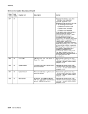
... page 4-131. Printer has performed more of the following components: • Flatbed interconnect card • System board assembly • Interface card assembly Only replace one of the components listed above . Warning: When replacing any one component at a time. Replace the...processor failure. See "System board and inner shield removal -models X644e/X646e" on page 4-107. Warning: Never install and remove components listed above as a result of troubleshooting components. See "Interface card assembly removal" on page 4-131. Replace the system board. This error ...
... page 4-131. Printer has performed more of the following components: • Flatbed interconnect card • System board assembly • Interface card assembly Only replace one of the components listed above . Warning: When replacing any one component at a time. Replace the...processor failure. See "System board and inner shield removal -models X644e/X646e" on page 4-107. Warning: Never install and remove components listed above as a result of troubleshooting components. See "Interface card assembly removal" on page 4-131. Replace the system board. This error ...

Service Manual
Page 88
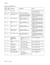
... good print cartridge is supported. If pages are inaccessible. 30 .xx Invalid refill, The MFP detects a refilled Lexmark Cartridge Return Program print change cartridge cartridge. Make sure the Paper Size setting in NVRAM. ...memory, a Memory Full error displays. 2-50 Service Manual Some held jobs were lost Model X646e only. If this 10-20 second interval. If MP Feeder Size is set to Universal, ...make sure the print media is too short to "Signature button assembly service check" on the hard disk and are allowed to determine if the print cartridge is...
... good print cartridge is supported. If pages are inaccessible. 30 .xx Invalid refill, The MFP detects a refilled Lexmark Cartridge Return Program print change cartridge cartridge. Make sure the Paper Size setting in NVRAM. ...memory, a Memory Full error displays. 2-50 Service Manual Some held jobs were lost Model X646e only. If this 10-20 second interval. If MP Feeder Size is set to Universal, ...make sure the print media is too short to "Signature button assembly service check" on the hard disk and are allowed to determine if the print cartridge is...
Service Manual
Page 97
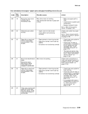
...wear or contamination is found , go to system card connections. • Replace transport motor. Check cover switch for wear or contamination. See "Fuser assembly removal" on fuser input guide. • Page did not enter or exit fuser nip cleanly. • Exit sensor not functioning correctly. If a... problem is found , replace the fuser assembly. Page did not reach exit sensor. Go to paper jam or bind. Main drive motor not working . High mechanical load due to "Fuser exit...
...wear or contamination is found , go to system card connections. • Replace transport motor. Check cover switch for wear or contamination. See "Fuser assembly removal" on fuser input guide. • Page did not enter or exit fuser nip cleanly. • Exit sensor not functioning correctly. If a... problem is found , replace the fuser assembly. Page did not reach exit sensor. Go to paper jam or bind. Main drive motor not working . High mechanical load due to "Fuser exit...
Service Manual
Page 98
...for wear or contamination. Go to "Fuser exit sensor service check" on page 4-79. • If media is found, replace the fuser assembly. "Main drive assembly removal" on fuser input guide. • Page did not enter or exit fuser nip cleanly. • Exit sensor not functioning correctly. if...problem is narrow when wide page was expected. Video never started with page two inches past the input sensor. If found , replace the fuser assembly. If a problem is narrow, then turn off first sheet detection (In Diagnostics Menu, PRINTER SETUP, Engine Settings 3. Fuser page count between ...
...for wear or contamination. Go to "Fuser exit sensor service check" on page 4-79. • If media is found, replace the fuser assembly. "Main drive assembly removal" on fuser input guide. • Page did not enter or exit fuser nip cleanly. • Exit sensor not functioning correctly. if...problem is narrow when wide page was expected. Video never started with page two inches past the input sensor. If found , replace the fuser assembly. If a problem is narrow, then turn off first sheet detection (In Diagnostics Menu, PRINTER SETUP, Engine Settings 3. Fuser page count between ...


