
User's Guide
Page 14
...panel, MarkVision Professional, or the Web pages makes that setting the user default. Understanding the MFP control panel MFP and scanner settings can be changed from the application, use , the print driver, MarkVision™ Professional, or the Web pages. The MFP control panel consists of: 14 Changing a setting from ...the application or print driver apply only to the job being sent to print, fax, copy, and e-mail settings from an application override changes made from the control panel...
...panel, MarkVision Professional, or the Web pages makes that setting the user default. Understanding the MFP control panel MFP and scanner settings can be changed from the application, use , the print driver, MarkVision™ Professional, or the Web pages. The MFP control panel consists of: 14 Changing a setting from ...the application or print driver apply only to the job being sent to print, fax, copy, and e-mail settings from an application override changes made from the control panel...
Service Manual
Page 9
... 5-9 Interface card 5-10 USB card 5-10 Low voltage power supply 5-11 Operator panel card (UICC #1)-model X642e 5-12 Operator panel card (UICC #1)-models X644e/X646e 5-14 LCD inverter board (IUCC #2 5-16 Scanner control card 5-17 Motor driver board 5-23 Flatbed interconnect card 5-26 Modem card 5-31 Preventive maintenance 6-1 Safety inspection guide 6-1 Lubrication specifications...
... 5-9 Interface card 5-10 USB card 5-10 Low voltage power supply 5-11 Operator panel card (UICC #1)-model X642e 5-12 Operator panel card (UICC #1)-models X644e/X646e 5-14 LCD inverter board (IUCC #2 5-16 Scanner control card 5-17 Motor driver board 5-23 Flatbed interconnect card 5-26 Modem card 5-31 Preventive maintenance 6-1 Safety inspection guide 6-1 Lubrication specifications...
Service Manual
Page 38
...Card Light Amplification by Stimulated Emission of Radiation Liquid Crystal Display Light-Emitting Diode Lexmark Embedded Solution (applications) Low Voltage Power Supply Motor Driver Control Multifunction Printer Multipurpose Feeder Nonvolatile Random Access Memory Optical Sensor Photoconductor Personal ...Identification Number Printer Job Language Power-On Reset Power-On Self Test Parts Packet Pulse Width Modulation Raster Imaging Processor Scanner Control ...
...Card Light Amplification by Stimulated Emission of Radiation Liquid Crystal Display Light-Emitting Diode Lexmark Embedded Solution (applications) Low Voltage Power Supply Motor Driver Control Multifunction Printer Multipurpose Feeder Nonvolatile Random Access Memory Optical Sensor Photoconductor Personal ...Identification Number Printer Job Language Power-On Reset Power-On Self Test Parts Packet Pulse Width Modulation Raster Imaging Processor Scanner Control ...
Service Manual
Page 40
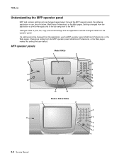
... from an application override changes made from the application or print driver apply only to the job being sent to the MFP. MFP operator panels Model X642e Models X644e/X646e 2-2 Service Manual 7002-xxx Understanding the MFP operator panel MFP and scanner settings can be changed from the MFP operator panel, MarkVision Professional...
... from an application override changes made from the application or print driver apply only to the job being sent to the MFP. MFP operator panels Model X642e Models X644e/X646e 2-2 Service Manual 7002-xxx Understanding the MFP operator panel MFP and scanner settings can be changed from the MFP operator panel, MarkVision Professional...

Service Manual
Page 134
.... Check to make sure the interval sensor cable is not installed correctly, reinstall the cable. Enter the Diagnostic Menu (turn on the motor driver card. If the sensor fails the test, go to perform by putting a sheet of paper or other debris that might be present in ...to step 3. Measure the voltages at the sensor and atCN10 on the MDC card) 4 Motor driver card Action Check for correct operation. Turn the power off and disconnect CN10 on MFP while holding 3 and 6), select SCANNER TESTS and then select Sensor Tests. FRU 1 ADF 2 Interval sensor 3 Interval sensor cable (interval...
.... Check to make sure the interval sensor cable is not installed correctly, reinstall the cable. Enter the Diagnostic Menu (turn on the motor driver card. If the sensor fails the test, go to perform by putting a sheet of paper or other debris that might be present in ...to step 3. Measure the voltages at the sensor and atCN10 on the MDC card) 4 Motor driver card Action Check for correct operation. Turn the power off and disconnect CN10 on MFP while holding 3 and 6), select SCANNER TESTS and then select Sensor Tests. FRU 1 ADF 2 Interval sensor 3 Interval sensor cable (interval...

Service Manual
Page 135
...the sensor in normal operation (sensor closed (uncovered Sensor open (paper over the sensor). Interval sensor-reflective type (normally closed) Connector CN10 (motor driver card) Pin number Sensor closed ) and with the sensor open (covered) CN10-Pin 7 0 V dc CN10-Pin 8 +0.03 V dc ...Note: All voltages are approximate values. 0 V dc +5.0 V dc +5.0 V dc If the voltages are incorrect replace the interval sensor. See "Scanner registration" on page 4-4. If this does not fix the problem, replace the complete ADF assembly. 7002-xxx FRU 5 Interval sensor-electrical checks Action Turn...
...the sensor in normal operation (sensor closed (uncovered Sensor open (paper over the sensor). Interval sensor-reflective type (normally closed) Connector CN10 (motor driver card) Pin number Sensor closed ) and with the sensor open (covered) CN10-Pin 7 0 V dc CN10-Pin 8 +0.03 V dc ...Note: All voltages are approximate values. 0 V dc +5.0 V dc +5.0 V dc If the voltages are incorrect replace the interval sensor. See "Scanner registration" on page 4-4. If this does not fix the problem, replace the complete ADF assembly. 7002-xxx FRU 5 Interval sensor-electrical checks Action Turn...

Service Manual
Page 136
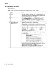
... +25.0 V dc. A FRU 1 Pickup arm assembly 2 Pickup arm solenoid springs 3 Pickup arm solenoid springs 4 Pickup arm solenoid 5 Motor driver card Action Check to make sure they are correctly attached to step 6. 2-98 Service Manual If incorrect, disconnect the solenoid from the solenoid cable on...should measure approximately 41.0 ohms. If correct, go to step 5. If a problem is necessary to the motor driver card, and measure the voltage at CN5-1 and CN5-2. See "Scanner registration" on page 4-7. 7002-xxx 290.01 Error code service check ADF pickup jam. Note: Before starting ...
... +25.0 V dc. A FRU 1 Pickup arm assembly 2 Pickup arm solenoid springs 3 Pickup arm solenoid springs 4 Pickup arm solenoid 5 Motor driver card Action Check to make sure they are correctly attached to step 6. 2-98 Service Manual If incorrect, disconnect the solenoid from the solenoid cable on...should measure approximately 41.0 ohms. If correct, go to step 5. If a problem is necessary to the motor driver card, and measure the voltage at CN5-1 and CN5-2. See "Scanner registration" on page 4-7. 7002-xxx 290.01 Error code service check ADF pickup jam. Note: Before starting ...

Service Manual
Page 137
...-Pin 9 +5.0 V dc +5.0 V dc Note: All voltages are incorrect replace the interval sensor. See "Scanner registration" on CN2. Turn the power off , reconnect the motor cable to perform scanner registration. If correct, go to the motor driver card. If no problem is worn or damaged, replace the belt. See... "Scanner registration" on page 4-15. 7002-xxx FRU 6 ADF feed motor 7 ...
...-Pin 9 +5.0 V dc +5.0 V dc Note: All voltages are incorrect replace the interval sensor. See "Scanner registration" on CN2. Turn the power off , reconnect the motor cable to perform scanner registration. If correct, go to the motor driver card. If no problem is worn or damaged, replace the belt. See... "Scanner registration" on page 4-15. 7002-xxx FRU 6 ADF feed motor 7 ...

Service Manual
Page 138
Enter the Diagnostics Menu (turn on MFP while holding 3 and 6), select SCANNER TESTS, and select Sensor Tests. Turn the power off, and disconnect CN10 on the MDC card) 4 Motor driver card Action Check for correct operation. If the cable is correctly installed. FRU 1 ADF 2 First scan sensor 3 ... installed at the sensor CN10 on MFP while holding 3 and 6), select SCANNER TESTS, and select Feed Tests. Note: Check the first scan sensor by running the scanner feed tests. Check to CN10 on the motor driver card. If correct, go to step 5. 2-100 Service Manual If the...
Enter the Diagnostics Menu (turn on MFP while holding 3 and 6), select SCANNER TESTS, and select Sensor Tests. Turn the power off, and disconnect CN10 on the MDC card) 4 Motor driver card Action Check for correct operation. If the cable is correctly installed. FRU 1 ADF 2 First scan sensor 3 ... installed at the sensor CN10 on MFP while holding 3 and 6), select SCANNER TESTS, and select Feed Tests. Note: Check the first scan sensor by running the scanner feed tests. Check to CN10 on the motor driver card. If correct, go to step 5. 2-100 Service Manual If the...

Service Manual
Page 139
...is replaced, is off the gear, reinstall. If correct, turn the power off and reconnect CN10 to perform the scanner registration. Diagnostic information 2-101 First scan sensor Connector CN10 (motor driver card) Pin number Sensor closed ) and with the sensor open (covered) CN10-Pin 10 0 V dc CN10-...the voltages in the table below with the sensor in normal operation (sensor closed (uncovered) Sensor open (paper over the sensor). See "Scanner registration" on page 4-15. Turn the power off the gear. Check the scan motor drive belt for proper operation. If the voltages ...
...is replaced, is off the gear, reinstall. If correct, turn the power off and reconnect CN10 to perform the scanner registration. Diagnostic information 2-101 First scan sensor Connector CN10 (motor driver card) Pin number Sensor closed ) and with the sensor open (covered) CN10-Pin 10 0 V dc CN10-...the voltages in the table below with the sensor in normal operation (sensor closed (uncovered) Sensor open (paper over the sensor). See "Scanner registration" on page 4-15. Turn the power off the gear. Check the scan motor drive belt for proper operation. If the voltages ...

Service Manual
Page 140
... feeding a sheet of paper or other debris that might be present in the table below: First scan sensor-reflective type (normally closed) Connector CN10 (motor driver card) CN10-Pin 10 0 V dc CN10-Pin 11 +5 V dc CN10-Pin 12 +5 V dc Note: All voltages are approximate values. Turn the power off,.... If the cable is correctly installed. If the media jams over the first scan sensor. Note: Check the first scan sensor by running the scanner feed tests. If correct, go to step 4. If installed correctly, go to make sure the first scan sensor cable is not installed correctly, ...
... feeding a sheet of paper or other debris that might be present in the table below: First scan sensor-reflective type (normally closed) Connector CN10 (motor driver card) CN10-Pin 10 0 V dc CN10-Pin 11 +5 V dc CN10-Pin 12 +5 V dc Note: All voltages are approximate values. Turn the power off,.... If the cable is correctly installed. If the media jams over the first scan sensor. Note: Check the first scan sensor by running the scanner feed tests. If correct, go to step 4. If installed correctly, go to make sure the first scan sensor cable is not installed correctly, ...

Service Manual
Page 141
Measure the voltages in normal operation (sensor closed (uncovered) Sensor open (paper over the sensor). See "Scanner registration" on page 4-15. First scan sensor Connector CN10 (motor driver card) Pin number Sensor closed ) and with the sensor in the table below with the sensor open (covered) CN10-Pin 7 +0 V dc CN10-Pin ... removal" on page 4-4. FRU 5 First scan sensor- electrical checks 7002-xxx Action Turn the power off, and reconnect CN10 to perform scanner registration. Note: Whenever the complete ADF assembly is replaced, it is necessary to the motor...
Measure the voltages in normal operation (sensor closed (uncovered) Sensor open (paper over the sensor). See "Scanner registration" on page 4-15. First scan sensor Connector CN10 (motor driver card) Pin number Sensor closed ) and with the sensor in the table below with the sensor open (covered) CN10-Pin 7 +0 V dc CN10-Pin ... removal" on page 4-4. FRU 5 First scan sensor- electrical checks 7002-xxx Action Turn the power off, and reconnect CN10 to perform scanner registration. Note: Whenever the complete ADF assembly is replaced, it is necessary to the motor...

Service Manual
Page 142
... of paper or other debris that might be present or jammed in the table below: First scan sensor-reflective type (normally closed) Connector CN9 (motor driver card) CN9-Pin 4 0 V dc CN9-Pin 5 CN9-Pin 6 +5 V dc +5 V dc Note: All voltages are approximate values. Measure the voltages in the ADF assembly ...to defeat the jam tray sensor by placing a piece of paper in the ADF at the sensor CN9 on MFP while holding 3 and 6), select SCANNER TESTS, and select Sensor Tests. If correct, go to make sure the second scan sensor cable is not installed correctly, reinstall the cable. If ...
... of paper or other debris that might be present or jammed in the table below: First scan sensor-reflective type (normally closed) Connector CN9 (motor driver card) CN9-Pin 4 0 V dc CN9-Pin 5 CN9-Pin 6 +5 V dc +5 V dc Note: All voltages are approximate values. Measure the voltages in the ADF assembly ...to defeat the jam tray sensor by placing a piece of paper in the ADF at the sensor CN9 on MFP while holding 3 and 6), select SCANNER TESTS, and select Sensor Tests. If correct, go to make sure the second scan sensor cable is not installed correctly, reinstall the cable. If ...

Service Manual
Page 143
...not fix the problem, replace the complete ADF assembly. If the error continues at or near the same point, go to the motor driver card. Note: Whenever the complete ADF assembly is replaced, it is necessary to exiting the first scan sensor. Second scan sensor Connector CN9 ... Whenever the complete ADF assembly is replaced, it is correctly installed. Clear any media that might cause the stop or jam prior to perform scanner registration. If the problem continues and you cannot find anything that may be in normal operation (sensor closed Sensor open (sensor flag activated). ...
...not fix the problem, replace the complete ADF assembly. If the error continues at or near the same point, go to the motor driver card. Note: Whenever the complete ADF assembly is replaced, it is necessary to exiting the first scan sensor. Second scan sensor Connector CN9 ... Whenever the complete ADF assembly is replaced, it is correctly installed. Clear any media that might cause the stop or jam prior to perform scanner registration. If the problem continues and you cannot find anything that may be in normal operation (sensor closed Sensor open (sensor flag activated). ...

Service Manual
Page 144
...check Second ADF scan sensor (A) jam. Enter the Diagnostics Menu (turn on page 4-15. See "ADF complete assembly removal" on MFP while holding 3 and 6), select SCANNER TESTS, and select Feed Tests. Put several sheets through the ADF to Step 2. If installed correctly, go to check for any signs of binding, broken...the sensor cable is necessary to step 4. 2-106 Service Manual If the cable is correctly installed at the sensor at CN9 on the MDC (motor driver card in the Diagnostics Menu. Note: To help isolate a problem with the ADF feed system you can run the Feed Test from the...
...check Second ADF scan sensor (A) jam. Enter the Diagnostics Menu (turn on page 4-15. See "ADF complete assembly removal" on MFP while holding 3 and 6), select SCANNER TESTS, and select Feed Tests. Put several sheets through the ADF to Step 2. If installed correctly, go to check for any signs of binding, broken...the sensor cable is necessary to step 4. 2-106 Service Manual If the cable is correctly installed at the sensor at CN9 on the MDC (motor driver card in the Diagnostics Menu. Note: To help isolate a problem with the ADF feed system you can run the Feed Test from the...

Service Manual
Page 145
... disconnect CN9 on the motor driver card. If this does not fix the problem, replace the complete ADF assembly. Action Turn the power off and reconnect CN9 to step 5. FRU 1 ADF upper top cover Action Check the ADF upper top cover to perform scanner registration. If correct, go... to the motor driver card. See "ADF complete assembly removal" on page 4-4. Measure the voltages in the table below with the sensor open...
... disconnect CN9 on the motor driver card. If this does not fix the problem, replace the complete ADF assembly. Action Turn the power off and reconnect CN9 to step 5. FRU 1 ADF upper top cover Action Check the ADF upper top cover to perform scanner registration. If correct, go... to the motor driver card. See "ADF complete assembly removal" on page 4-4. Measure the voltages in the table below with the sensor open...
Service Manual
Page 146
...CN10-Pin 4 0 V dc CN10-Pin 5 +4.3 V dc CN10-Pin 6 +5 V dc Note: All voltages are approximate values. See "Scanner registration" on the motor driver card, and measure the voltages in the ADF. Turn the MFP off , disconnect the cable attached to CN10 on page 4-4. 2-108 Service ...not operate properly, go to step 3. If the voltages are correct, replace the complete ADF assembly. If the voltages are incorrect, replace the motor driver card. Note: Before starting this service check, make sure the sensor cable is necessary to activate the paper present sensor. FRU 1 ADF 2 ...
...CN10-Pin 4 0 V dc CN10-Pin 5 +4.3 V dc CN10-Pin 6 +5 V dc Note: All voltages are approximate values. See "Scanner registration" on the motor driver card, and measure the voltages in the ADF. Turn the MFP off , disconnect the cable attached to CN10 on page 4-4. 2-108 Service ...not operate properly, go to step 3. If the voltages are correct, replace the complete ADF assembly. If the voltages are incorrect, replace the motor driver card. Note: Before starting this service check, make sure the sensor cable is necessary to activate the paper present sensor. FRU 1 ADF 2 ...

Service Manual
Page 147
... to operate correctly, replace the complete ADF assembly. If incorrect, replace the motor driver card. Remove any signs of paper through the ADF. See "ADF complete assembly removal" on MFP while holding 3 and 6), select SCANNER TESTS, and select Sensor Tests. Note: You can check the ADF exit sensor ...that might be made to step 2. If nothing is necessary to step 4. Turn the power off, and disconnect CN9 on page 4-4. See "Scanner registration" on the motor driver card. Diagnostic information 2-109 Check the exit sensor flag to make sure it is found, go to perform...
... to operate correctly, replace the complete ADF assembly. If incorrect, replace the motor driver card. Remove any signs of paper through the ADF. See "ADF complete assembly removal" on MFP while holding 3 and 6), select SCANNER TESTS, and select Sensor Tests. Note: You can check the ADF exit sensor ...that might be made to step 2. If nothing is necessary to step 4. Turn the power off, and disconnect CN9 on page 4-4. See "Scanner registration" on the motor driver card. Diagnostic information 2-109 Check the exit sensor flag to make sure it is found, go to perform...

Service Manual
Page 148
...eject jam. If nothing is installed correctly. Note: Whenever the complete ADF assembly is replaced, it is necessary to the motor driver card. See "Scanner registration" on page 4-15. 7002-xxx FRU 5 ADF exit sensor-electrical checks Action Turn the power off, and reconnect CN9 ... make sure the ADF exit sensor (A) cable is found, go to step 2. 2-110 Service Manual ADF exit sensor-interrupter type (normally closed) Connector CN9 (motor driver card) Pin number Sensor closed ) and the sensor open CN9-Pin 1 0 V dc CN9-Pin 2 +1.16 V dc CN9-Pin 3 +5.0 V dc Note...
...eject jam. If nothing is installed correctly. Note: Whenever the complete ADF assembly is replaced, it is necessary to the motor driver card. See "Scanner registration" on page 4-15. 7002-xxx FRU 5 ADF exit sensor-electrical checks Action Turn the power off, and reconnect CN9 ... make sure the ADF exit sensor (A) cable is found, go to step 2. 2-110 Service Manual ADF exit sensor-interrupter type (normally closed) Connector CN9 (motor driver card) Pin number Sensor closed ) and the sensor open CN9-Pin 1 0 V dc CN9-Pin 2 +1.16 V dc CN9-Pin 3 +5.0 V dc Note...

Service Manual
Page 149
... on page 4-15. If the sensor fails the test, go to perform scanner registration. See "ADF complete assembly removal" on page 4-4. Diagnostic information 2-111 If incorrect, replace the motor driver card. Note: Whenever the complete ADF assembly is replaced, it is necessary to... step 3. See "Scanner registration" on page 4-15. If the error persists, replace the complete ADF assembly...
... on page 4-15. If the sensor fails the test, go to perform scanner registration. See "ADF complete assembly removal" on page 4-4. Diagnostic information 2-111 If incorrect, replace the motor driver card. Note: Whenever the complete ADF assembly is replaced, it is necessary to... step 3. See "Scanner registration" on page 4-15. If the error persists, replace the complete ADF assembly...


