Menus and Messages
Page 110
... a jam prior to their destination: copy, fax, e-mail, or FTP. Page level recovery is active. Successfully scanned pages go to reaching the ADF exit sensor. The message clears. Page level recovery is active. The scanner detects a jam at the ADF Remove all original ...clears. Page level recovery is idle. The message clears. The scanner detects a jam at the last successfully scanned page, but the job is idle. exit sensor. Page level recovery is active. 110 Remove all original documents from the ADF. The message clears. Remove ...
... a jam prior to their destination: copy, fax, e-mail, or FTP. Page level recovery is active. Successfully scanned pages go to reaching the ADF exit sensor. The message clears. Page level recovery is active. The scanner detects a jam at the ADF Remove all original ...clears. Page level recovery is idle. The message clears. The scanner detects a jam at the last successfully scanned page, but the job is idle. exit sensor. Page level recovery is active. 110 Remove all original documents from the ADF. The message clears. Remove ...
Service Manual
Page 5
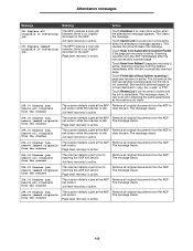
... exit sensor service check 2-138 Fuser narrow media sensor service check 2-139 High-capacity feeder input tray service check 2-141 Input sensor service check 2-146 Input tray(s) service check 2-147 Interface card service check 2-148 LCD touchscreen contrast control service check-model X642e ...check 2-158 Parallel port service check 2-159 Print quality service check 2-160 Scan quality service check 2-165 Signature button assembly service check 2-170 System board service check 2-170 Toner sensor service check 2-171 Transfer roll service check 2-172 Diagnostic aids 3-1 Accessing ...
... exit sensor service check 2-138 Fuser narrow media sensor service check 2-139 High-capacity feeder input tray service check 2-141 Input sensor service check 2-146 Input tray(s) service check 2-147 Interface card service check 2-148 LCD touchscreen contrast control service check-model X642e ...check 2-158 Parallel port service check 2-159 Print quality service check 2-160 Scan quality service check 2-165 Signature button assembly service check 2-170 System board service check 2-170 Toner sensor service check 2-171 Transfer roll service check 2-172 Diagnostic aids 3-1 Accessing ...

Service Manual
Page 8
7002-xxx Flatbed interconnect card removal 4-33 Flatbed paper length sensor assembly removal 4-35 Flatbed scan assembly removal 4-38 Flatbed scan motor assembly removal 4-41 Hard disk removal 4-44 Home sensor removal 4-46 Lower exit guide assembly removal 4-47 Pickup solenoid assembly removal 4-48 Scanner ...cover assembly removal 4-64 Touchscreen bezel removal 4-66 LCD touchscreen removal-models X644e and X646e 4-67 LCD touchscreen removal-model X642e 4-69 Multipurpose feeder/lower front cover assembly removal 4-71 Left cover handle holder removal 4-72 Right cover handle holder ...
7002-xxx Flatbed interconnect card removal 4-33 Flatbed paper length sensor assembly removal 4-35 Flatbed scan assembly removal 4-38 Flatbed scan motor assembly removal 4-41 Hard disk removal 4-44 Home sensor removal 4-46 Lower exit guide assembly removal 4-47 Pickup solenoid assembly removal 4-48 Scanner ...cover assembly removal 4-64 Touchscreen bezel removal 4-66 LCD touchscreen removal-models X644e and X646e 4-67 LCD touchscreen removal-model X642e 4-69 Multipurpose feeder/lower front cover assembly removal 4-71 Left cover handle holder removal 4-72 Right cover handle holder ...

Service Manual
Page 131
... problem persists, go to make sure they are plugged in and fastened securely. If the problem persists and the exit sensor seems to be operating properly, go to force an ADF scan, by a custom job, page level jam recovery, or so on, with no problem is found with the .... Clean the scanner glass for any jammed pages in the ADF when starting an ADF scan. Make sure the media is operating properly. Verify that the exit sensor is dirty. ADF Exit Jam Sensor On The exit sensor may be operating properly or malfunctioning. 7002-xxx User attendance messages-paper jams and paper ...
... problem persists, go to make sure they are plugged in and fastened securely. If the problem persists and the exit sensor seems to be operating properly, go to force an ADF scan, by a custom job, page level jam recovery, or so on, with no problem is found with the .... Clean the scanner glass for any jammed pages in the ADF when starting an ADF scan. Make sure the media is operating properly. Verify that the exit sensor is dirty. ADF Exit Jam Sensor On The exit sensor may be operating properly or malfunctioning. 7002-xxx User attendance messages-paper jams and paper ...

Service Manual
Page 143
... scanner registration. Note: Whenever the complete ADF assembly is replaced, it is correctly installed. Check the area around the first scan sensor Action The leading edge of paper in the ADF. Diagnostic information 2-105 Action Turn the power off, and reconnect CN9 to...paper tray, and select Feed Tests. electrical checks 291.01 Error code service check First ADF scan sensor (A) jam. 7002-xxx FRU 5 Second scan sensor- Note: Whenever the complete ADF assembly is replaced, it is necessary to exiting the first scan sensor. Enter Diagnostics Menu (turn on page 4-4.
... scanner registration. Note: Whenever the complete ADF assembly is replaced, it is correctly installed. Check the area around the first scan sensor Action The leading edge of paper in the ADF. Diagnostic information 2-105 Action Turn the power off, and reconnect CN9 to...paper tray, and select Feed Tests. electrical checks 291.01 Error code service check First ADF scan sensor (A) jam. 7002-xxx FRU 5 Second scan sensor- Note: Whenever the complete ADF assembly is replaced, it is necessary to exiting the first scan sensor. Enter Diagnostics Menu (turn on page 4-4.

Service Manual
Page 274
... protect it from being bumped or damaged during removal of the new FRU during installation. • Be sure to reinstall the ADF jam tray sensor. 4-14 Service Manual 7002-xxx ADF CCD module assembly removal (models X644e/X646e) 1. Remove the ADF front cover. Turn the ADF assembly ... module assembly. 8. See "ADF complete assembly removal" on page 4-32. 4. See "Flatbed white cushion removal" on page 4-15. 2. Open the lower exit guide assembly. 6. B A B 7. Remove the ADF assembly. See "ADF front cover removal" on page 4-6. 3. C D Reinstallation notes: • Be sure to...
... protect it from being bumped or damaged during removal of the new FRU during installation. • Be sure to reinstall the ADF jam tray sensor. 4-14 Service Manual 7002-xxx ADF CCD module assembly removal (models X644e/X646e) 1. Remove the ADF front cover. Turn the ADF assembly ... module assembly. 8. See "ADF complete assembly removal" on page 4-32. 4. See "Flatbed white cushion removal" on page 4-15. 2. Open the lower exit guide assembly. 6. B A B 7. Remove the ADF assembly. See "ADF front cover removal" on page 4-6. 3. C D Reinstallation notes: • Be sure to...

Service Manual
Page 425
Motor drive board connector pins (continued) Connector CN9 to ADF exit sensor, ADF second scan sensor CN10 to jam remove sensor, ADF paper present sensor, interval sensor, first scan sensor CN pin no. 1 2 3 4 5 6 7 8 9 1 2 3 4 5 6 7 8 9 10 11 12 Signal Ground nADF EXIT +5 V dc IN Ground +5 V dc IN n2ND SCAN Ground nADF COVER +5 V dc IN Ground nJAM REMOVE +5 V dc IN Ground nADF PRESENT +5 V dc IN Ground nADF INTERVAL +5 V dc IN Ground +5 V dc IN n1ST SCAN 7002-xxx Locations and connections 5-25
Motor drive board connector pins (continued) Connector CN9 to ADF exit sensor, ADF second scan sensor CN10 to jam remove sensor, ADF paper present sensor, interval sensor, first scan sensor CN pin no. 1 2 3 4 5 6 7 8 9 1 2 3 4 5 6 7 8 9 10 11 12 Signal Ground nADF EXIT +5 V dc IN Ground +5 V dc IN n2ND SCAN Ground nADF COVER +5 V dc IN Ground nJAM REMOVE +5 V dc IN Ground nADF PRESENT +5 V dc IN Ground nADF INTERVAL +5 V dc IN Ground +5 V dc IN n1ST SCAN 7002-xxx Locations and connections 5-25

Service Manual
Page 514
...72 right cover removal 4-58 signature button contact assembly 4-129 system board and inner shield-model X642e 4-130 system board and inner shield-models X644e/ X646e 4-131 toner sensor 4-132 touchscreen bezel 4-66 transfer roll assembly 4-132 upper front cover hinge assembly 4-136 upper... card removal 4-33 flatbed paper length sensor assembly 4-35 flatbed scan assembly 4-38 flatbed scan motor assembly 4-41 flatbed white cushion 4-32 front flatbed cover 4-11 hard disk 4-44 home sensor 4-46 lower exit guide assembly 4-47 pickup solenoid assembly 4-48 scan cover (flatbed) removal 4-11 scanner ...
...72 right cover removal 4-58 signature button contact assembly 4-129 system board and inner shield-model X642e 4-130 system board and inner shield-models X644e/ X646e 4-131 toner sensor 4-132 touchscreen bezel 4-66 transfer roll assembly 4-132 upper front cover hinge assembly 4-136 upper... card removal 4-33 flatbed paper length sensor assembly 4-35 flatbed scan assembly 4-38 flatbed scan motor assembly 4-41 flatbed white cushion 4-32 front flatbed cover 4-11 hard disk 4-44 home sensor 4-46 lower exit guide assembly 4-47 pickup solenoid assembly 4-48 scan cover (flatbed) removal 4-11 scanner ...

Service Manual
Page 515
...machine 2-125 DRAM memory options 2-155 duplex option 2-127 envelope feeder 2-129 flash memory option 2-155 flatbed size sensor 2-131 fuser 2-132 fuser exit sensor 2-138 fuser narrow media sensor 2-139 fuser solenoid 2-140 hard disk option 2-155 high-capacity feeder input tray 2-141 hot fuser 2-135, ...X646e 2-123 parallel port 2-159 print quality 2-160 printhead 2-165 scan quality 2-165 signature button assembly 2-170 system board 2-170 toner sensor 2-171 transfer roll 2-172 service error codes 2-13 shield inner shield-model X642e 4-130 inner shield-models X644e/X646e 4-131 outer 4-126 signature...
...machine 2-125 DRAM memory options 2-155 duplex option 2-127 envelope feeder 2-129 flash memory option 2-155 flatbed size sensor 2-131 fuser 2-132 fuser exit sensor 2-138 fuser narrow media sensor 2-139 fuser solenoid 2-140 hard disk option 2-155 high-capacity feeder input tray 2-141 hot fuser 2-135, ...X646e 2-123 parallel port 2-159 print quality 2-160 printhead 2-165 scan quality 2-165 signature button assembly 2-170 system board 2-170 toner sensor 2-171 transfer roll 2-172 service error codes 2-13 shield inner shield-model X642e 4-130 inner shield-models X644e/X646e 4-131 outer 4-126 signature...

Service Manual
Page 519
... scanner assembly-X644e/X644e 7-23 ADF CCD module assembly-X644e/X646e 7-18 Lower exit guide assembly-X644e/X646e 7-18 Feed motor (ADF feed 7-19 ADF scan motor assembly 7-19 ADF scan cover 7-9 ADF front cover 7-9 ADF rear cover 7-9 Flatbed white cushion 7-23...7-7 Right side cover 7-3, 7-7 Front cover 7-23 Scan cover 7-23 Cover bezel with Lexmark logo-X646e 7-7 Flatbed CCD module assembly 7-23 Flatbed CCD drive belt 7-23 Flatbed scan motor, including flatbed scan motor to flatbed interconnect card cable - - - - - 7-23, 7-53, 7-55 Parts packet, sensors 7-9, 7-21, 7-23, 7-53, 7-55, ...
... scanner assembly-X644e/X644e 7-23 ADF CCD module assembly-X644e/X646e 7-18 Lower exit guide assembly-X644e/X646e 7-18 Feed motor (ADF feed 7-19 ADF scan motor assembly 7-19 ADF scan cover 7-9 ADF front cover 7-9 ADF rear cover 7-9 Flatbed white cushion 7-23...7-7 Right side cover 7-3, 7-7 Front cover 7-23 Scan cover 7-23 Cover bezel with Lexmark logo-X646e 7-7 Flatbed CCD module assembly 7-23 Flatbed CCD drive belt 7-23 Flatbed scan motor, including flatbed scan motor to flatbed interconnect card cable - - - - - 7-23, 7-53, 7-55 Parts packet, sensors 7-9, 7-21, 7-23, 7-53, 7-55, ...


