User's Guide
Page 207
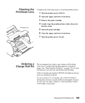
..., dry lint-free cloth. 5 Insert the print cartridge. 6 Close the upper and lower front doors. 7 Turn the printer power On (|). See "Print Quality Problems" on page 178 for information about Lexmark Authorized Supplies Dealers in your printer. Installation instructions are included in the U.S. In other countries, contact the place where you order a new charge roll...
..., dry lint-free cloth. 5 Insert the print cartridge. 6 Close the upper and lower front doors. 7 Turn the printer power On (|). See "Print Quality Problems" on page 178 for information about Lexmark Authorized Supplies Dealers in your printer. Installation instructions are included in the U.S. In other countries, contact the place where you order a new charge roll...

User's Guide
Page 310
...153 Invalid Network 1 Code 153 line 1 messages 152 Menus Disabled 153 Network Card Busy 154 Not Ready 154 Performing Self Test 154 Power Saver 154 Printing Directory List 155 Printing Font List 155 Printing Job Accounting Stat 155 Printing Menu Settings 155 Printing Quality Test Pages 155... Restoring Factory Defaults 157 Waiting 157 warning messages 158 status, printer MarkVision 25 298 Index Stop button 36 storing print cartridge 194 print material 123 streaks on page 179 Substitute Size (Paper Menu) 49 Sun 27 supplies charge roll kit, ordering 195 print cartridge installing 5 ordering 193 ...
...153 Invalid Network 1 Code 153 line 1 messages 152 Menus Disabled 153 Network Card Busy 154 Not Ready 154 Performing Self Test 154 Power Saver 154 Printing Directory List 155 Printing Font List 155 Printing Job Accounting Stat 155 Printing Menu Settings 155 Printing Quality Test Pages 155... Restoring Factory Defaults 157 Waiting 157 warning messages 158 status, printer MarkVision 25 298 Index Stop button 36 storing print cartridge 194 print material 123 streaks on page 179 Substitute Size (Paper Menu) 49 Sun 27 supplies charge roll kit, ordering 195 print cartridge installing 5 ordering 193 ...

Service Manual
Page 5
... 4-24 Paper Alignment Assembly 4-25 Pick Roll 4-27 Printhead 4-28 Redrive Assembly 4-29 Right Side Frame 4-30 Transfer Roller 4-30 Connector Locations 5-1 Low Voltage Power Supply 5-1 High Voltage Power Supply 5-2 Engine Board 5-4 Interconnect Board 5-10 Option Tray Board 5-12 Parts Catalog 6-1 Assembly 1: Covers 6-2 Assembly 2: Frame 6-6 Assembly 3: Printhead 6-8 Assembly 4: Paper Feed - Alignment 6-12 Assembly 6: Paper...
... 4-24 Paper Alignment Assembly 4-25 Pick Roll 4-27 Printhead 4-28 Redrive Assembly 4-29 Right Side Frame 4-30 Transfer Roller 4-30 Connector Locations 5-1 Low Voltage Power Supply 5-1 High Voltage Power Supply 5-2 Engine Board 5-4 Interconnect Board 5-10 Option Tray Board 5-12 Parts Catalog 6-1 Assembly 1: Covers 6-2 Assembly 2: Frame 6-6 Assembly 3: Printhead 6-8 Assembly 4: Paper Feed - Alignment 6-12 Assembly 6: Paper...
Service Manual
Page 23
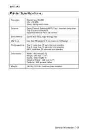
4045-XXX Printer Specifications Acoustics Operating:
4045-XXX Printer Specifications Acoustics Operating:
Service Manual
Page 25
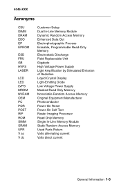
... FRU GB HVPS LASER LCD LED LVPS MROM NVRAM OEM PC POR POST RIP ROM SIMM SRAM UPR V ac V dc Customer Setup Dual In-Line Memory Module Dynamic Random Access Memory Enhanced Data Out Electrophotographic Process Erasable, Programmable Read-Only Memory Electrostatic Discharge Field Replaceable Unit Gigabyte High Voltage Power Supply Light Amplification...
... FRU GB HVPS LASER LCD LED LVPS MROM NVRAM OEM PC POR POST RIP ROM SIMM SRAM UPR V ac V dc Customer Setup Dual In-Line Memory Module Dynamic Random Access Memory Enhanced Data Out Electrophotographic Process Erasable, Programmable Read-Only Memory Electrostatic Discharge Field Replaceable Unit Gigabyte High Voltage Power Supply Light Amplification...
Service Manual
Page 47
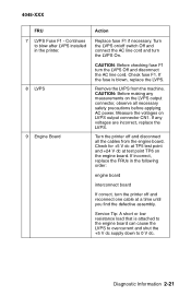
..., replace the LVPS. Check fuse F1. CAUTION: Before checking fuse F1 turn the printer off and reconnect one cable at test point TP6 on /off and disconnect all necessary safety precautions before applying AC power. Measure the voltages on the LVPS output connector, observe all the cables from the .... Continues to 0 V dc. If the fuse is attached to the engine board can cause the LVPS to overcurrent and shut the +5 V dc supply down to blow after LVPS installed in the following order: engine board interconnect board If correct, turn the LVPS Off and disconnect the AC line...
..., replace the LVPS. Check fuse F1. CAUTION: Before checking fuse F1 turn the printer off and reconnect one cable at test point TP6 on /off and disconnect all necessary safety precautions before applying AC power. Measure the voltages on the LVPS output connector, observe all the cables from the .... Continues to 0 V dc. If the fuse is attached to the engine board can cause the LVPS to overcurrent and shut the +5 V dc supply down to blow after LVPS installed in the following order: engine board interconnect board If correct, turn the LVPS Off and disconnect the AC line...
Service Manual
Page 135
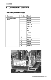
Connector Locations Low Voltage Power Supply Connector CN1 Interconnect Board Pin No. 1 2 3 4 5 6 7 8 9 10 11 12 13 14 Signal +5 V dc +5 V dc Ground +24 V dc +24 V dc Ground N/A +5 V dc Ground Ground +24 V dc Ground Ground Heat On Connector Locations 5-1 4045-XXX 5.
Connector Locations Low Voltage Power Supply Connector CN1 Interconnect Board Pin No. 1 2 3 4 5 6 7 8 9 10 11 12 13 14 Signal +5 V dc +5 V dc Ground +24 V dc +24 V dc Ground N/A +5 V dc Ground Ground +24 V dc Ground Ground Heat On Connector Locations 5-1 4045-XXX 5.
Service Manual
Page 136
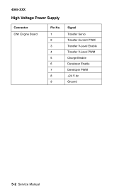
4045-XXX High Voltage Power Supply Connector CN1 Engine Board Pin No. 1 2 3 4 5 6 7 8 9 Signal Transfer Servo Transfer Current PWM Transfer V-Level Enable Transfer V-Level PWM Charge Enable Developer Enable Developer PWM +24 V dc Ground 5-2 Service Manual
4045-XXX High Voltage Power Supply Connector CN1 Engine Board Pin No. 1 2 3 4 5 6 7 8 9 Signal Transfer Servo Transfer Current PWM Transfer V-Level Enable Transfer V-Level PWM Charge Enable Developer Enable Developer PWM +24 V dc Ground 5-2 Service Manual
Service Manual
Page 189
... B Base Sensor Test 3-14 Button Test 3-9 C Cable Locations 3-29 Configuration Mode 3-1 Connector Locations Engine Board 5-4 High Voltage Power Supply 5-2 Interconnect Board 5-10 Low Voltage Power Supply 5-1 Option Tray Board 5-12 D Demo Mode 3-4 Device Tests 3-17 Diagnostic Aids Configuration Mode 3-1 Demo Mode 3-4 Device Tests ... 3-2 Paper Feed Tests Base Sensor Test 3-14 PPDS Emulation 3-3 Print Quality Test Pages 3-2 Print Registration 3-6 Print Tests 3-6 Printer Setup 3-14 Edge to Edge 3-16 Factory Defaults 3-16 Parallel Strobe Adjust 3-16 Serial Number 3-16 Setting Configuration ID 3-15...
... B Base Sensor Test 3-14 Button Test 3-9 C Cable Locations 3-29 Configuration Mode 3-1 Connector Locations Engine Board 5-4 High Voltage Power Supply 5-2 Interconnect Board 5-10 Low Voltage Power Supply 5-1 Option Tray Board 5-12 D Demo Mode 3-4 Device Tests 3-17 Diagnostic Aids Configuration Mode 3-1 Demo Mode 3-4 Device Tests ... 3-2 Paper Feed Tests Base Sensor Test 3-14 PPDS Emulation 3-3 Print Quality Test Pages 3-2 Print Registration 3-6 Print Tests 3-6 Printer Setup 3-14 Edge to Edge 3-16 Factory Defaults 3-16 Parallel Strobe Adjust 3-16 Serial Number 3-16 Setting Configuration ID 3-15...


