Service Manual
Page 4
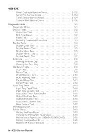
... 3-15 Output Bin Feed Test 3-15 Output Bin Sensor Test 3-16 Output Bin X Sensor Test 3-16 Base Sensor Test 3-17 Print Registration 3-18 Printer Setup 3-19 Setting the Page Count 3-19 Viewing the Permanent Page Count 3-19 Maintenance Page Count (2420/2450/2455/3455) . . . . .... 3-20 Setting Configuration ID 3-20 Restore EP Factory Defaults 3-21 iv 4059 Service Manual 4059-XXX Smart Cartridge Service Check 2-102 Serial Port Service Check 2-104 Toner Sensor Service Check 2-104 Transfer Roll Service Check 2-105 Diagnostic Aids 3-1 Diagnostic Mode 3-1 Device ...
... 3-15 Output Bin Feed Test 3-15 Output Bin Sensor Test 3-16 Output Bin X Sensor Test 3-16 Base Sensor Test 3-17 Print Registration 3-18 Printer Setup 3-19 Setting the Page Count 3-19 Viewing the Permanent Page Count 3-19 Maintenance Page Count (2420/2450/2455/3455) . . . . .... 3-20 Setting Configuration ID 3-20 Restore EP Factory Defaults 3-21 iv 4059 Service Manual 4059-XXX Smart Cartridge Service Check 2-102 Serial Port Service Check 2-104 Toner Sensor Service Check 2-104 Transfer Roll Service Check 2-105 Diagnostic Aids 3-1 Diagnostic Mode 3-1 Device ...

Service Manual
Page 28
... If a service error code is displayed, go to the "Service Error Codes" on the first line of the printer. Diagnostic Information Start CAUTION: Remove power from the printer before you have a symptom, go to the "Symptom Tables" on the side of the display unless Power Saver ... Ready is displayed, go to the printer. If a service error code appears while you lift or set the printer down. User error messages are working on the machine, go to repair a malfunctioning printer. User status messages provide the user with a print cartridge, paper jam, option, port, and ...
... If a service error code is displayed, go to the "Service Error Codes" on the first line of the printer. Diagnostic Information Start CAUTION: Remove power from the printer before you have a symptom, go to the "Symptom Tables" on the side of the display unless Power Saver ... Ready is displayed, go to the printer. If a service error code appears while you lift or set the printer down. User error messages are working on the machine, go to repair a malfunctioning printer. User status messages provide the user with a print cartridge, paper jam, option, port, and ...

Service Manual
Page 43
...and open or the print cartridge is missing. Open the rear door of the printer. Insert Cartridge or Close Door This message displays when the printer's front door is open the duplex rear door. Open the printer's upper front door and remove the print cartridge to remove the jammed pages... 27X Paper Jam Check Output Bin X Paper is jammed between the printer's input and exit sensors. 4059-XXX User Error Messages User Error Message Explanation 200 Paper Jam Remove Cartridge Paper is jammed at the printer exit sensor. Diagnostic Information 2-16 Try opening Tray X. If the ...
...and open or the print cartridge is missing. Open the rear door of the printer. Insert Cartridge or Close Door This message displays when the printer's front door is open the duplex rear door. Open the printer's upper front door and remove the print cartridge to remove the jammed pages... 27X Paper Jam Check Output Bin X Paper is jammed between the printer's input and exit sensors. 4059-XXX User Error Messages User Error Message Explanation 200 Paper Jam Remove Cartridge Paper is jammed at the printer exit sensor. Diagnostic Information 2-16 Try opening Tray X. If the ...

Service Manual
Page 44
... this 10-20 second interval. If pages are allowed to read from the print cartridge twice. Note: This error indicates the printer was able to print, they are not reprinted once a good print cartridge is not operating correctly. This error message also displays on the setting of the ...Machine Class ID the printer may take the printer 10-20 seconds to print the formatted data. Try another model 3455 print cartridge. The printer determines the paper length is inserted. If pages are allowed to print, then they ...
... this 10-20 second interval. If pages are allowed to read from the print cartridge twice. Note: This error indicates the printer was able to print, they are not reprinted once a good print cartridge is not operating correctly. This error message also displays on the setting of the ...Machine Class ID the printer may take the printer 10-20 seconds to print the formatted data. Try another model 3455 print cartridge. The printer determines the paper length is inserted. If pages are allowed to print, then they ...

Service Manual
Page 48
..., then "Toner Low" displays. If any , displays. User Message Toner Low Tray X Missing Tray X Empty Tray X Low Explanation If the toner cartridge is closed. Tray X Missing status clears whenever Tray X is removed. Note: Tray X Low clears whenever Tray X goes empty, or Tray X is... reinserted. When Tray X is reinserted, it is not displayed for the Envelope Feeder or Multipurpose Feeder. Note: The printer cannot detect when the envelope feeder or multipurpose feeder are missing, then "Tray X Missing" displays (where X designates which tray (1 through 5) is...
..., then "Toner Low" displays. If any , displays. User Message Toner Low Tray X Missing Tray X Empty Tray X Low Explanation If the toner cartridge is closed. Tray X Missing status clears whenever Tray X is removed. Note: Tray X Low clears whenever Tray X goes empty, or Tray X is... reinserted. When Tray X is reinserted, it is not displayed for the Envelope Feeder or Multipurpose Feeder. Note: The printer cannot detect when the envelope feeder or multipurpose feeder are missing, then "Tray X Missing" displays (where X designates which tray (1 through 5) is...

Service Manual
Page 51
The operator panel displays one and a half row of the base printer by observing the following: 1. The output expander option exit rollers turn the printer On, it performs a Power-On Self Test. The duplex option is powered off. 13. The main fan turns on the display. 4059-...warm up from a cold start than a warm start. 7. The fuser lamp turns on . 2. The developer drive assembly drives the developer shaft in the toner cartridge. 10. Models 2420, 2450 2455 and 3455 only - The auxiliary fan turns on . 9. The LED comes on . Diagnostic Information 2-24 Check for correct POST...
The operator panel displays one and a half row of the base printer by observing the following: 1. The output expander option exit rollers turn the printer On, it performs a Power-On Self Test. The duplex option is powered off. 13. The main fan turns on the display. 4059-...warm up from a cold start than a warm start. 7. The fuser lamp turns on . 2. The developer drive assembly drives the developer shaft in the toner cartridge. 10. Models 2420, 2450 2455 and 3455 only - The auxiliary fan turns on . 9. The LED comes on . Diagnostic Information 2-24 Check for correct POST...

Service Manual
Page 53
... page 2-99. Banding" on page 2-100. Toner on backside of printed page" on backside of copy Unable to clear a "32-Unsupported Print Cartridge" User Error Message Action Go to "Print Quality - Residual image Print quality - Toner on page 2-102. Go to the"High Capacity Feeder Input... Tray Service Check" on page 2-86. High Capacity Feeder Option (2000 Sheet) Symptom The printer does not recognize the high capacity feeder option installed. Go to "Smart Cartridge Service Check" on page 2-61. Random Marks" on edge of printed page Print quality - Action Go...
... page 2-99. Banding" on page 2-100. Toner on backside of printed page" on backside of copy Unable to clear a "32-Unsupported Print Cartridge" User Error Message Action Go to "Print Quality - Residual image Print quality - Toner on page 2-102. Go to the"High Capacity Feeder Input... Tray Service Check" on page 2-86. High Capacity Feeder Option (2000 Sheet) Symptom The printer does not recognize the high capacity feeder option installed. Go to "Smart Cartridge Service Check" on page 2-61. Random Marks" on edge of printed page Print quality - Action Go...

Service Manual
Page 73
Remove the controller board and toner cartridge from the machine. If correct, check the voltage at J10-15. If incorrect, check the continuity of the erase lamp lines in the main harness. ... Lamp Service Check Error code 928 may be observed through the front of the machine with the cover open and print cartridge removed. The lamps can be displayed when the printer detects that the erase lamp assembly, cable or engine board is defective, both the erase lamp and lens are replaced as...
Remove the controller board and toner cartridge from the machine. If correct, check the voltage at J10-15. If incorrect, check the continuity of the erase lamp lines in the main harness. ... Lamp Service Check Error code 928 may be observed through the front of the machine with the cover open and print cartridge removed. The lamps can be displayed when the printer detects that the erase lamp assembly, cable or engine board is defective, both the erase lamp and lens are replaced as...
Service Manual
Page 118
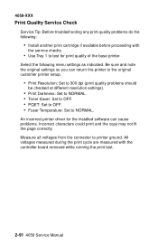
... cycle are measured with the service checks. • Use Tray 1 to test for the installed software can return the printer to the original customer printer setup. • Print Resolution: Set to 300 dpi (print quality problems should be checked at different resolution settings). ...troubleshooting any print quality problems do the following menu settings as indicated. An incorrect printer driver for print quality of the base printer. Select the following : • Install another print cartridge if available before proceeding with the controller board removed while running the print test....
... cycle are measured with the service checks. • Use Tray 1 to test for the installed software can return the printer to the original customer printer setup. • Print Resolution: Set to 300 dpi (print quality problems should be checked at different resolution settings). ...troubleshooting any print quality problems do the following menu settings as indicated. An incorrect printer driver for print quality of the base printer. Select the following : • Install another print cartridge if available before proceeding with the controller board removed while running the print test....

Service Manual
Page 121
Symptom 1 Random Marks Action Check the print cartridge for correct operation. Check the gearbox assembly for any signs of fuzzy print is due to loose material moving around inside the printer and attaching to the rolls. Check the transfer roll for any feed roller or in the main drive gearbox assembly, alignment assembly...
Symptom 1 Random Marks Action Check the print cartridge for correct operation. Check the gearbox assembly for any signs of fuzzy print is due to loose material moving around inside the printer and attaching to the rolls. Check the transfer roll for any feed roller or in the main drive gearbox assembly, alignment assembly...

Service Manual
Page 123
...the alignment assembly. Some slick or coated papers may try to improve the print quality by rough papers or non-Lexmark toner cartridges. Some problems occur with printers that run the print test. Background Service Tip: Some background problems can be caused by increasing the transfer setting....917 inch) apart 13 Lines spaced 114.79 mm (4.519 inch) apart Action Replace the FRUs in the following order: toner cartridge main drive gearbox assembly Replace the redrive assembly. Replace the FRUs in the following order: alignment assembly main drive gearbox assembly Replace ...
...the alignment assembly. Some slick or coated papers may try to improve the print quality by rough papers or non-Lexmark toner cartridges. Some problems occur with printers that run the print test. Background Service Tip: Some background problems can be caused by increasing the transfer setting....917 inch) apart 13 Lines spaced 114.79 mm (4.519 inch) apart Action Replace the FRUs in the following order: toner cartridge main drive gearbox assembly Replace the redrive assembly. Replace the FRUs in the following order: alignment assembly main drive gearbox assembly Replace ...

Service Manual
Page 126
... the alignment assembly, main drive assembly and all other paper feed components for signs of damage and for proper connection to the HVPS and print cartridge. Banding appears as vertical black bands on a uniformly gray page. Print Quality - 4059-XXX Print Quality - Black bands on outer edges of the...dark horizontal lines on one side of the page, check the charge roll counterbalance spring on the page. Replace as it feeds thru the printer, especially in the speed of graphics printed on that the spring is difficult to detect except on a page with your finger to while you...
... the alignment assembly, main drive assembly and all other paper feed components for signs of damage and for proper connection to the HVPS and print cartridge. Banding appears as vertical black bands on a uniformly gray page. Print Quality - 4059-XXX Print Quality - Black bands on outer edges of the...dark horizontal lines on one side of the page, check the charge roll counterbalance spring on the page. Replace as it feeds thru the printer, especially in the speed of graphics printed on that the spring is difficult to detect except on a page with your finger to while you...

Service Manual
Page 127
... at J10-8 on the page. Residual Image Service Tip: Install a new print cartridge if available before doing this does not correct the problem, replace the engine board....Printer Printing Test Page J10-8 voltage changes from 0 V dc to +4 V dc If the voltage does not vary, check the continuity of line J10-8 in the front cable harness. Repair or replace as necessary. Check the charge links and arms for any signs of toner buildup or other parts inside the print cartridge.... If there is continuity, replace the HVPS. Turn the printer Off and check the resistance between J10-7 and...
... at J10-8 on the page. Residual Image Service Tip: Install a new print cartridge if available before doing this does not correct the problem, replace the engine board....Printer Printing Test Page J10-8 voltage changes from 0 V dc to +4 V dc If the voltage does not vary, check the continuity of line J10-8 in the front cable harness. Repair or replace as necessary. Check the charge links and arms for any signs of toner buildup or other parts inside the print cartridge.... If there is continuity, replace the HVPS. Turn the printer Off and check the resistance between J10-7 and...
Service Manual
Page 129
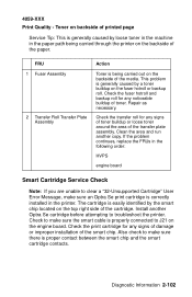
...sure there is generally caused by a toner buildup on the fuser hotroll or backup roll. Clean the area and run another Optra Se cartridge before attempting to J21 on the top right side of the paper. 4059-XXX Print Quality - Install another copy. Diagnostic Information... 2-102 Toner on backside of printed page Service Tip: This is properly connected to troubleshoot the printer. Check to clear a "32-Unsupported Cartridge" User Error Message, make sure the smart cable is generally caused by the smart chip located on the engine ...
...sure there is generally caused by a toner buildup on the fuser hotroll or backup roll. Clean the area and run another Optra Se cartridge before attempting to J21 on the top right side of the paper. 4059-XXX Print Quality - Install another copy. Diagnostic Information... 2-102 Toner on backside of printed page Service Tip: This is properly connected to troubleshoot the printer. Check to clear a "32-Unsupported Cartridge" User Error Message, make sure the smart cable is generally caused by the smart chip located on the engine ...

Service Manual
Page 156
...Page one copy, perform these steps again. 3-23 4059 Service Manual Select the media source. 3. Pages two and three only contain graphics. Turn the printer off. 2. If continuous is selected, Return or Stop can be printed on one copy of the Print Quality Test pages. Note: The Print Test Page... a duplex option. The Print Quality Test pages must always be selected to allow printing of the print quality test pages with the toner cartridge lockout function disabled. 4059-XXX The contents of the Print Test Page varies depending on the media installed in Print Quality and Paper Feed...
...Page one copy, perform these steps again. 3-23 4059 Service Manual Select the media source. 3. Pages two and three only contain graphics. Turn the printer off. 2. If continuous is selected, Return or Stop can be printed on one copy of the Print Quality Test pages. Note: The Print Test Page... a duplex option. The Print Quality Test pages must always be selected to allow printing of the print quality test pages with the toner cartridge lockout function disabled. 4059-XXX The contents of the Print Test Page varies depending on the media installed in Print Quality and Paper Feed...

Service Manual
Page 162
Base Printer Error Message 200 - Remove Cartridge This message indicates that paper is jammed at the sensor too late. ...prior to activating the input sensor flag, the sensor not detecting paper over the sensor or paper arriving at the printer input sensor. Error Message 24x (x=Tray 1 through sensor of the option above tray x. 3-29 4059 Service ...This message indicates the paper is bent and not aligned properly to allow paper to the duplex option. Remove Cartridge This message indicates the paper is jammed exiting the fuser assembly in the redrive at the input to feed correctly...
Base Printer Error Message 200 - Remove Cartridge This message indicates that paper is jammed at the sensor too late. ...prior to activating the input sensor flag, the sensor not detecting paper over the sensor or paper arriving at the printer input sensor. Error Message 24x (x=Tray 1 through sensor of the option above tray x. 3-29 4059 Service ...This message indicates the paper is bent and not aligned properly to allow paper to the duplex option. Remove Cartridge This message indicates the paper is jammed exiting the fuser assembly in the redrive at the input to feed correctly...

Service Manual
Page 170
...reassembly. 4059-XXX Screw Identification Table The following table contains screw types, locations, and quantities necessary to attach 1 frame laser cover mounting 5 4-7 4059 Service Manual Reference Number Screw Type Location Purpose Qty M3.5x8 mm right side frame to Thread...left attach 2 frame stacker duct to frame mounting 2 cartridge hold down assembly mounting 2 MPT deflector mounting 2 fuser to frame mounting 2 interconnect board shield ground attach 2 engine board shield to service the printer. Each screw callout in the removal procedure graphic displays ...
...reassembly. 4059-XXX Screw Identification Table The following table contains screw types, locations, and quantities necessary to attach 1 frame laser cover mounting 5 4-7 4059 Service Manual Reference Number Screw Type Location Purpose Qty M3.5x8 mm right side frame to Thread...left attach 2 frame stacker duct to frame mounting 2 cartridge hold down assembly mounting 2 MPT deflector mounting 2 fuser to frame mounting 2 interconnect board shield ground attach 2 engine board shield to service the printer. Each screw callout in the removal procedure graphic displays ...

Service Manual
Page 223
... assembly latch from its mounting on the right mounting post. 2. 4059-XXX Transfer Roll Assembly 1. Pivot the transfer roll assembly toward the front of the printer. 3. Open the multipurpose tray and remove the tray from the left and right pivot arms and remove the transfer roll assembly. Remove the upper deflector... careful not to lose the O-ring on the right side frame and slide to the right. 3. Open the upper front cover and remove the print cartridge. 2.
... assembly latch from its mounting on the right mounting post. 2. 4059-XXX Transfer Roll Assembly 1. Pivot the transfer roll assembly toward the front of the printer. 3. Open the multipurpose tray and remove the tray from the left and right pivot arms and remove the transfer roll assembly. Remove the upper deflector... careful not to lose the O-ring on the right side frame and slide to the right. 3. Open the upper front cover and remove the print cartridge. 2.

Service Manual
Page 347
... 2-86 Parallel Port 2-89 Print Quality 2-91 Printhead 2-89 Serial Port 2-104 Smart Cartridge 2-102 Toner Sensor 2-104 Transfer Roll 2-105 Setting Configuration ID 3-20 Setting the Page Count 3-19 Status Messages 2-12 Symptom Tables 2-25 Base Printer 2-25 Duplex 2-27 Envelope Feeder Option 2-27 High Capacity Feeder Option 2-26 Output Expander...
... 2-86 Parallel Port 2-89 Print Quality 2-91 Printhead 2-89 Serial Port 2-104 Smart Cartridge 2-102 Toner Sensor 2-104 Transfer Roll 2-105 Setting Configuration ID 3-20 Setting the Page Count 3-19 Status Messages 2-12 Symptom Tables 2-25 Base Printer 2-25 Duplex 2-27 Envelope Feeder Option 2-27 High Capacity Feeder Option 2-26 Output Expander...

Maintenance Manual
Page 2
...on the second line of the printer. 2. You should now see "Reset Maint Cnt" on ; Continue to finish initializing. 2. Optra S, Optra T, & T Series Maintenance Kit Instructions, Continued Transfer Roll (Fig. 6): 1. Open the top cover and remove the toner cartridge. do not touch the roller. ... they are keyed two ways: (a) the hole in a T650, then release them. Maintenance Reset Instructions, Lexmark Optra S, Optra T, T52x, T62x, T63x, T64x, T65x Optra S 24xx and Optra SE 3455 1. Optra T and & T52x, T62x, T63x 1. when "Performing Self Test" appears on the plastic hub; You...
...on the second line of the printer. 2. You should now see "Reset Maint Cnt" on ; Continue to finish initializing. 2. Optra S, Optra T, & T Series Maintenance Kit Instructions, Continued Transfer Roll (Fig. 6): 1. Open the top cover and remove the toner cartridge. do not touch the roller. ... they are keyed two ways: (a) the hole in a T650, then release them. Maintenance Reset Instructions, Lexmark Optra S, Optra T, T52x, T62x, T63x, T64x, T65x Optra S 24xx and Optra SE 3455 1. Optra T and & T52x, T62x, T63x 1. when "Performing Self Test" appears on the plastic hub; You...


